

Page 1

USER‘S GUIDE
EE820 – CO2 Sensor for Demanding Applications
SCOPE OF SUPPLY
• EE820 Sensor according to ordering guide
• Mounting set (screws and rowl plugs / screw anchors)
• Cable gland (only for EE820-HVxxxE1xxx with cable gland)
• Mating M12x1 connector for self assembly (only for EE820-HVxAxE9xxx with M12x1 plug)
• Two self-adhesive labels for configuration changes (see user guide at www.epluse.com/relabeling)
• Quick Guide - For EE820 with M12 plug and EE820 with RS485 output
• Test report according to DIN EN 10204 – 2.2
ACCESSORIES / SPARE PARTS
ACCESSORIES (see datasheet “Accessories”):
USB configuration adapter HA011066
Product configuration software EE-PCS (free download: www.epluse.com/EE820)
Mating M12x1 connector for self assembly HA010707
Connection cable M12x1 socket - flying leads
• 1.5 m
• 5 m (16.4 ft) HA010820
• 10 m (32.8 ft) HA010821
Protective cap for female M12 connectors HA010781
Protective cap for male M12 connectors HA010782
Power supply adapter V03
(3.3 ft) HA010819
SPARE PARTS:
Forced air circulation module, without cover EE820-FAC (HA011302)
Cover complete with filter and mounting screw EE820-COVER (HA011303)
CAUTION
• The sensor shall not be exposed to extreme mechanical or thermal stress.
• For use in polluted, dirty environment is essential to close tightly the sensor cover as well as the cable glad or conduit
adapter in order to avoid pollution ingress into the enclosure.
• This device is not appropriate for safety, emergency stop or other critical applications where device malfunction or failure could
cause injury to human beings.
DIMENSIONS
±0.3
90
mm
±0.11
3.54
“
5mm
0.2“
46mm
1.81“
FOR CONDUIT
INSTALLATION
101mm
3.98“
80.6mm
3.17“
19mm
0.75“
CABLE GLAND M16x1.5
M12x1 Plug
Mating M12x1 connector for self assembly is
included in the scope of supply
Page 2
EE820 with M12 plug does not require any wiring inside the device. The external mounting holes allow the device to be mounted without
opening the front cover. The mating M12x1 cable plug for self assembly is included in the scope of supply. Please see EE820 data sheet
for optional M12 plugs and cables.
EE820 with cable gland: Use a matching wrench to install the cable gland (in the scope of supply) onto the EE820 enclosure.
EE820 with conduit connection for the North American market: use a flat screwdriver to knock open the blind, carefully, in order to
avoid damaging the electronics inside the enclosure. The conduit adapter is not included in the scope of supply. The M16x1.5 opening
for the cable gland shall be tightly closed using the blind plug included in the scope of supply.
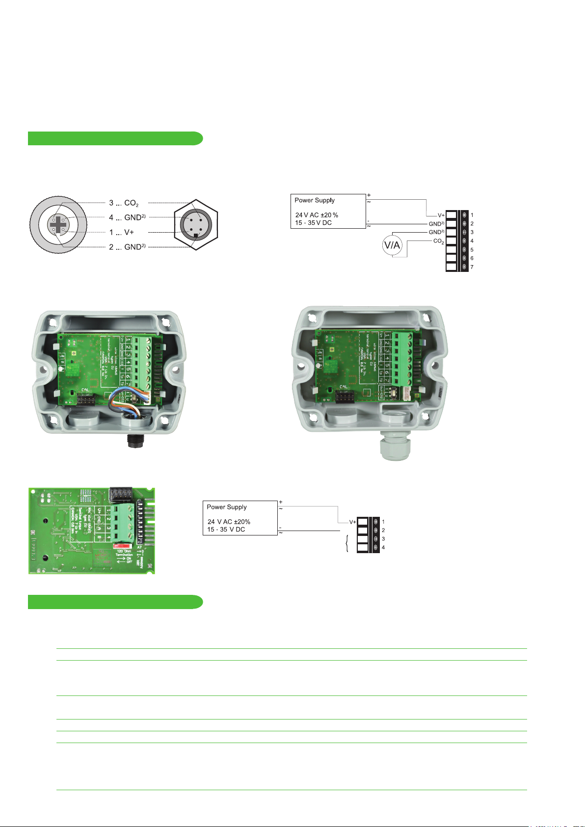
CONNECTION DIAGRAM
EE820 WITH ANALOGUE OUTPUT
EE820 WITH M12 PLUG
1) Mating M12x1 connector for self assembly is included in the scope of supply
2) Very important: for failure-free operation and performance according to the
specs the supply GND and the measurement GND must be
wired separately.
1)
EE820 WITH CABLE GLAND
EE820 WITH RS485 INTERFACE
EE820-HVXJ3
GND
A
RS485
B
EE820-HVxJ3
TECHNICAL DATA
(Modification rights reserved)
Measured values
Measuring principle dual wavelength non-dispersive infrared technology (NDIR)
Measurement range 0...2 000 / 5 000 / 10 000 ppm
Accuracy at 25 °C
and 1 013 mbar
0...10 000 ppm: < ± (100 ppm +5 % of mv)
Response time t
140 s (fast, with forced air circulation module)
Temperature dependency typ. ± (1 + CO
Sample rate approx. 15 s
Output
Analogue
0...2 000 / 5 000 / 10 000 ppm 0-5 / 0-10 V -1mA < I
4-20 mA R
(77 °F) 0...2 000 ppm: < ± (50 ppm +2 % of mv) mv = measured value
(14.7 psi) 0...5 000 ppm: < ± (50 ppm +3 % of mv)
, typ. 300 s (standard)
63
concentration [ppm] / 1 000) ppm/°C (-20...45 °C) (-4...113 °F)
2
< 1 mA
L
< 500 Ohm R
L
= load resistance
L
Page 3
Digital Interface RS485 with max. 32 unit load devices on one bus
Protocol Modbus RTU or BACnet MS/TP
General
Supply voltage 24 V AC ±20% 15 - 35 V DC
Current consumption, typ. 15 mA + output current, for standard response time
60 mA + output current, for fast response time
Current peak, max. 350 mA for 0.3 s (analogue output)
150 mA for 0.3 s (RS-485 interface)
Warm up time
1)
< 5 min
Enclosure material Polycarbonate, UL94V-0 approved
Protection class IP54
Electrical connection Screw terminals 2.5 mm² or M12 plug
Electromagnetic compatibility EN61326-1 EN61326-2-3 Industrial Environment
FCC Part 15 ICES-003 ClassB
Working conditions -20...60 °C
Storage conditions -20...60 °C
1) for performance according to specification
(-4...140 °F) 0...100 % RH (non-condensing)
(-4...140 °F) 0...95 % RH (non-condensing)
SETUP AND ADJUSTMENT
The EE820 is ready to use and does not require any configuration by the user. The factory setup of EE820 corresponds to the type
number ordered. For ordering guide please see data sheet at www.epluse.com/EE820.
If needed, the user can change the factory setup by using the optional USB Configuration Adapter (HA011066) and the Product
Configuration Software EE-PCS (available for free download at www.epluse.com/configurator). One can change CO
scaling of the outputs, digital settings and perform CO2 adjustment/calibration.
output signal,
2
Note: The EE820 must not be connected to any additional power supply when using the USB Configuration Adapter (HA011066).
PC
HA011066
EE820
ANALOGUE VERSION
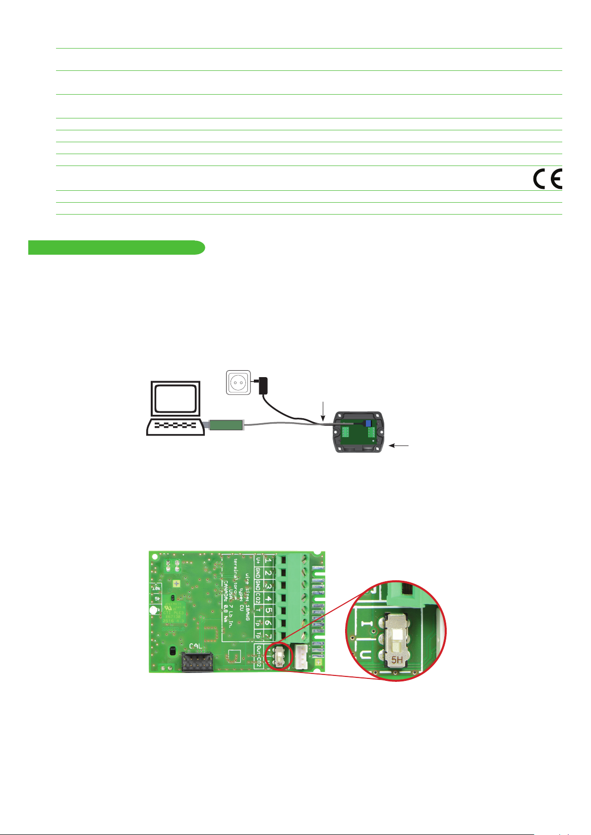
CHANGING THE OUTPUT SIGNAL:
The output signal can be changed from voltage to current or vice-versa.
Set the output signal selection switch to I for current 4 - 20 mA output or to U for voltage 0 - 10 V output. The original CO
does not change and the calibration data remains valid.
output range
2
Example:
Factory setup: voltage output (U), output scale: 0 - 10 V = 0 - 5000 ppm
User setup (after setting the output signal selection switch to I): current output (I), output scale: 4 - 20 mA = 0 - 5000 ppm.
CHANGING THE OUTPUT SCALE:
The scaling of the output can be changed by using the USB Configuration Adapter (HA011066) and EE-PCS.
Example:
The initial scaling of the output is 4 - 20 mA = 0 - 5000 ppm.
The output scale after the change can be 4 - 20 mA = 400 - 4000 ppm.
Page 4

Important:
0 0 0 0 0 0 0 0
0
1 1 0 1 0 0 0 0
0
• After changing the factory setup (output signal and/or output scale) the original type number on the EE820 identification label loses
its validity; it does not match any longer the device setup.
• The return to factory setup function of EE-PCS restores the original adjustment/calibration of the device, but does not affect the user
setup for output signal and output scale.
DIGITAL VERSION
HARDWARE
The bus termination shall be realized with 120 Ohm resistor (slide switch on the board).
Very important:
For proper function the power supply must be strong enough to ensure supply voltage within the specified range (see technical data) at
any time and at all devices in the bus. This is particularly relevant when using long and thin cables which can cause high voltage drop.
Please note that a single EE820 requires peak current of 150 mA.
ADDRESS SWITCH
Address setting via EE-PCS Product Configuration Software:
All Dip-Switches at position 0 → address has to be set via Product Configuration Software
1
Modbus (Slave device): factory setting EE820: 67 (permitted values: 1…247).
BACnet (Master device): factory setting EE820: 67 (permitted values: 0…127).
Example: Slave address is set via configuration software.
ADDRESS SWITCH
Address setting via Dip-Switch:
Modbus (Slave device): Setting the Dip-Switch to any other address than 0, overrules the slave
1
address set via configuration software (permitted values: 1…247).
BACnet (Master device): Setting the Dip-Switch to any other address than 0, overrules the slave
address set via configuration software.
BACnet Note: permitted values are 0…127. The 8th bit of the Dip-Switch is ignored
(ID 127 = 0111 111).
To set address 0 via Dip-Switch, the 8th bit shall be set to 1 (ID 0 = 1000 0000).
Example: Slave address set to 11 (= 0000 1011 binary).
BACNET SETUP
Please see PICS (Product Implementation Conformance Statement) - available on www.epluse.com/EE820.
MODBUS SETUP
The measured values are saved as a 32 bit float value and 16 bit signed integer.
The EE820 factory setting for the slave-ID (Modbus address) is 67 as an integer 16 bit value.
This ID can be changed by the user in the register 60001 (0x00), permitted values are 1…247.
The serial number as ASCII-code is located at read register address 30001-30008 (16 bit per address).
The firmware version is located at register address 30009 (bit 15...8 = major release; bit 7...0 = minor release).
FLOAT (read register):
Function code /
Register number1) [Dec]
31061 0x424 CO
31063 0x426 CO
1) Register number starts from 1 2) Register address starts from 0
Register
address
2)
[HEX]
Parameter
name
average [ppm]
2
RAW [ppm]
2
INTEGER (read register):
Function code /
Register number1) [Dec]
34031 0xFBE CO
34032 0xFBF CO
*1 is the scale 1:1 (e.g.: 800 is equivalent to 800 ppm)
Register
address
2)
[HEX]
Parameter
name
2
2
average [ppm] * 1
RAW [ppm] * 1
INTEGER (write register):
Function code /
Register number1) [Dec]
60001 0x00 Slave-ID (modbus address)*
60002 0x01 Modbus protocol settings**
* If the ID is set via DIP-Switch the response will be NAK.
** For Modbus protocol setting please see Application Note Modbus AN0103 at www.epluse.com
Register
address
2)
[HEX]
Parameter
name
INFO (read register):
Function code /
Register number1) [Dec]
30001 0x00 Serial number (as ASCII)
30009 0x08 Firmware version
Register
address
2)
[HEX]
Parameter
name
MODBUS RTU EXAMPLE
Example of MODBUS RTU command for reading the CO2 (float value) CO2 = 1288,34375 ppm from the register 0x424
Device EE820; slave ID 67 [43 in HEX]
Reference document, chapter 6.3: http://www.modbus.org/docs/Modbus_Application_Protocol_V1_1b.pdf
Page 5

Request [Hex]: 43 03 04 24 00 02 8A 12
Modbus ID
address
Request [Hex]: 43 03 04 24 00 02 8A 12
Function
code
Starting
address Hi
Starting
address Lo
No. of
register Hi
No. of
register Lo
CRC
Response [Hex]: 43 03 04 0B 00 44 A1 68 AB
Modbus ID
address
Response [Hex]: 43 03 04 0B 00 44 A1 68 AB
Function
code
Byte count
Register 1
value Hi
Register 1
value Lo
Register 2
value Hi
Register 2
value Lo
CRC
Mobus floating point format
For decoding of float values (stored according standard IEEE754), please refer to AN0103, chapter 7
Example:
Response [Hex] Value in decimal
44 A1 0B 00 1288.34375
Protocol setting:
Address, baudrate, parity and stop bits can be set via:
1. Product Configurator Software (available on www.epluse.com/ee820)
2. Modbus protocol (please see Application Note Modbus (available on www.epluse.com/ee820)
MAINTENANCE
Even in case of use in dirty and dusty environment, the electronics of EE820 are very well protected by the enclosure and the filter on
the front cover. Do not attempt in any way to clean the inside of the device.
In case of dirt deposits on the exterior of the device, this can be cleaned by weeping it gently with a soft, light wet cloth. The enclosure
must be closed during the cleaning. Do not use solvent-based cleaning agents; these might affect the enclosure and the labels. Do not
attempt to clean the filter on the front cover, as it would only lead to its faster clogging.
In a polluted environment, the filter on the front cover of EE820 might get clogged in a long run. This is more likely to happen for the
EE820 with forced air circulation. Longer response time indicates a clogged filter. In such a case the entire front cover shall be replaced
by an original new one (see spare parts and instruction below).
Protection filters caps for M12 connector are available to preserve the contacts of plug / socket in case of temporary removing of sensor
(see accessories).
REPLACEMENT / RETROFIT FORCED AIR CIRCULATION MODULE
Blue connector
cut-out 3
cut-out 1
cut-out 2
restraint A
restraint B
EE820-FAC EE820-COVER
Caution:
The EE820-FAC Forced Air Circulation Module is an ESD sensitive device and shall be handled at all times according to the general
precautions for handling of ESD sensitive equipment.
Page 6

REPLACING
For replacing an existing EE820-FAC module remove first the old EE820-FAC module:
• Disconnect the blue connector from the main EE820 board.
1)
2)
2.
1.
INSTALLING
• Release the old EE820-FAC by acting on restraint A.
For installing the new EE820-FAC:
• Observe the position of the A and B restraints in the cover and of the corresponding cut-outs 1 and 2 in the EE820-FAC board.
• Insert first the EE820-FAC into the B restraints. Than press the EE820-FAC as in the picture below, till in snaps into the A restraints.
2.
1.
“CLICK“
• Connect the blue connector of the EE820-FAC to the blue socket on the main EE820 board.
• Place the cover on the EE820 so that the cut-out 3 matches the location of the blue connector.
Page 7

• Fix the cover with the 4 bayonett screws D.
DD
D
D
USA
FCC notice:
This equipment has been tested and found to comply with the limits for a Class B digital device, pursuant to part 15 of the FCC Rules. These limits are
designed to provide reasonable protection against harmful interference in a residential installation. This equipment generates, uses and can radiate radio
frequency energy and, if not installed and used in accordance with the installation manual, may cause harmful interference to radio communications.
However, there is no guarantee that interference will not occur in a particular installation. If this equipment does cause harmful interference to radio or
television reception, which can be determined by turning the equipment off and on, the user is encouraged to try to correct the interference by one or
more of the following measures:
- Reorient or relocate the receiving antenna.
- Increase the separation between the equipment and receiver.
- Connect the equipment into an outlet on a circuit different from that to which thereceiver is connected.
- Consult the dealer or an experienced radio/TV technician for help.
CANADIAN
ICES-003 Issue 5:
CAN ICES-3 B / NMB-3 B
INFORMATION
+43 7235 605 0 / info@epluse.com
Langwiesen 7 • A-4209 Engerwitzdorf
Tel: +43 7235 605-0 • Fax: +43 7235 605-8
info@epluse.com • www.epluse.com
LG Linz Fn 165761 t • UID-Nr. ATU44043101
Place of Jurisdiction: A-4020 Linz • DVR0962759
BA_EE820_e // v1.5 // Modification rights reserved
 Loading...