

Page 1
USER‘S GUIDE
EE800 - HVAC Room Transmitter for CO2, Temperature and Relative Humidity
GENERAL
EE800 combines CO2, temperature (T) and relative humidity (RH) measurement in one device with modern design. Additionally, it
calculates the dewpoint temperature (Td). EE800 with analogue outputs features an optional passive T sensor, while at EE800 with
RS485 additional physical quantities are available on the Modbus RTU and BACnet MS/TP interface: absolute humidity (dv), mixing
ratio (r), enthalpy (h), frost point temperature (Tf) and water vapor partial pressure (e).
It incorporates the E+E dual wavelength NDIR CO
and offers outstanding long term stability.
EE800 is available with:
• Three voltage outputs (0-5 V or 0-10 V) for CO
• Two analogue outputs (0-5 V, 0-10 V or 4-20 mA ) for CO
• Modbus RTU or BACnet MS/TP interface, where all physical quantities, as above, are available according to the model ordered.
sensor, which compensates for ageing effects, is highly insensitive to pollution
2
, T and RH or Td, with an optional passive T output, or
2
and T, with an optional passive T output, or
2
CAUTION
• The device shall not be exposed to extreme mechanical or thermal stress.
• This device is not appropriate for safety, emergency stop or other critical applications where device malfunction or failure could
cause injury to human beings.
• The electronics board is an ESD sensitive device, please handle it accordingly and avoid touching it during installation.
• Please allow min. 5 minutes warm up time for the device to reach the specified measurement performance.
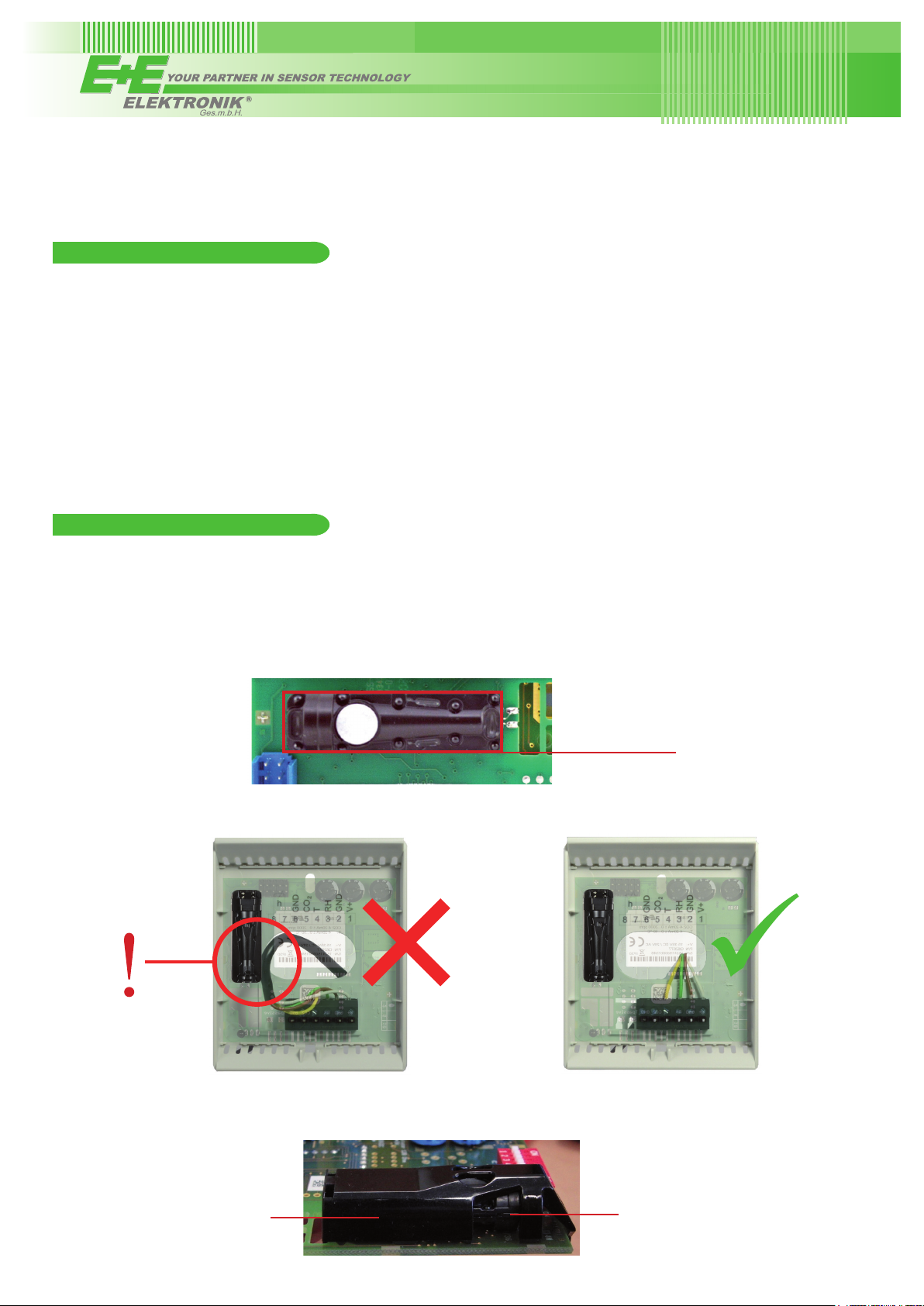
• The sensing cell shall not be exposed to any mechanical stress.
CO2 Sensing Cell
• The connecting cable or wires shall be positioned so that they do not impact with the sensing cell. Failure to comply with this
may lead to relevant measurement errors.
• The latest generation of EE800 (after August 2017) features a protection cap for the CO2 sensing cell. Although this facilitates
the handling during installation and diminishes the chances of unintended mechanical impact onto the cell, please observe the
wiring guidelines as above. Do not attempt to remove the protection cap.
Protection cap
CO2 Sensing Cell
Page 2
DIMENSIONS / MOUNTING
B
C
A
D
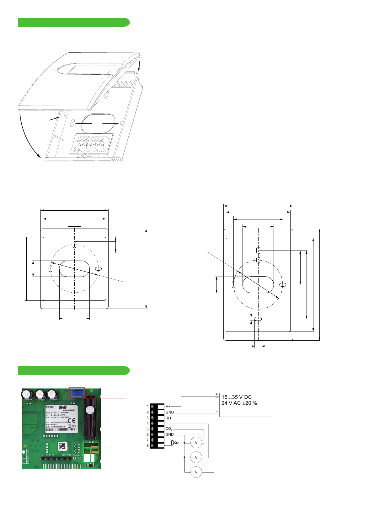
The electronics of EE800 are located in the front cover, which can be easily snapped on/off once the back cover is fixed onto the wall
(D = mounting holes) and wired.
OPENING THE ENCLOSURE
Press to release the latch A till the enclosure can be opened. Use a
screwdriver or a pen.
CLOSING THE ENCLOSURE
Set the front cover into flute B, rotate it like C and press it onto the
back cover till the latch A snaps in.
IMPORTANT
In order to protect the front cover and the electronics from typical
construction site pollution (such as painting of the walls) the front cover
should be snapped on only after the construction works are completed.
As EE800 is generally mounted onto a conduit box, for accurate
measurement results it is important to tighten the conduit box for
avoiding false air ingress (along the electrical tubes inside the wall)
into the EE800 enclosure.
EU version US version
85 / 3.35“
79.7 / 3.14“
4 / 0.16“
85 / 3.35“
79.7 / 3.14“
60 / 2.36“
38.2 / 1.5“
20
0.79“
80 / 3.15“
38.2 / 1.5“
CONNECTION DIAGRAM
EE800 VOLTAGE OUTPUT
8 / 0.31“
Ø 60
2.36“
confi guration
connector
100 / 3.94“
Ø 60
2.36“
20
0.79“
4 / 0.16“
8 / 0.31“
*
*
41.65 / 1.64“
136 / 5.35“
114.2 / 4.5“
83.3 / 3.28“
Output: 0-5 V
0-10 V
Page 3

Output: 0-5 V
0-10 V
EE800 CURRENT OUTPUT
Output: 0-5 V
0-10 V
Output: 4-20 mA
confi guration
connector
*
*
Output: 4-20 mA
* Very important: for failure-free operation and performance according to the specs the supply GND and the
measurement GND must be wired separately.
EE800 DIGITAL INTERFACE
Connection on the electronics board.
Screw terminals appropriate for daisy-chain wiring
confi guration connector
termination resistor
MODBUS AND BACNET
HARDWARE
• The bus termination shall be realized with 120 Ohm resistor, switch on the board.
• Very important:
For proper function the power supply must be strong enough to ensure supply voltage within the specified range (see technical
data) at any time and at all devices in the bus. This is particularly relevant when using long and thin cables which can cause high
voltage drop; please note that a single EE800 requires peak current of 150 mA.
ADDRESS SETTINGS
ADDRESS SWITCH
Slave address setting via EE-PCS Product Confi guration Software:
1
All switches at position 0 → address has to be set via confi guration software
(factory setting: 241...Modbus / 3...BACnet).
0
Example: Slave address is set via confi guration software.
0 0 0 0 0 0 0 0
ADDRESS SWITCH
Slave address setting via Dip-Switch:
1
1 1 0 1 0 0 0 0
Setting the Dip-Switch to any other address than 0 overwrites the slave address
set via confi guration software.
0
Example: Slave address set to 11 (=00001011 binary).
BACNET INFOS
Please see PICS (Product Implementation Conformance Statement) - available on www.epluse.com/EE800)
Page 4

MODBUS-MAP
The measured values are saved as a 32Bit fl oat value from 0x19 to 0x2F.
The factory setting for the Slave-ID is 241 as an integer 16Bit value. This ID can be customised in the register 60001 (0x00)
(value margin 1 - 247 permitted).
The serial number as ASCII-code is located at register address 30001-30008.
The firmwareversion is located at register address 30009.
The required units (metric or non-metric) must be selected in the „Ordering guide“, see EE800 data sheet.
FLOAT (read register):
Register
address
30026 0x19 temperature [°C], [°F]
30028 0x1B relative humidity [%]
30030 0x1D water vapour partial pressure [°C], [°F]
30032 0x1F dew point temperature [°C], [°F]
30036 0x23 absolute humidity [g/m³], [g/ft³]
30038 0x25 maxing ratio [g/kg], [gr/lb]
30040 0x27 specifi c enthalpy [kJ/kg], [BTU/lb]
30042 0x29 frost point temperature [°C], [°F]
30046 0x2D CO
30048 0x2F CO
Communication
address
Parameter
name
Raw* [ppm]
2
[ppm]
2
INFO (read register):
Register
address
30001 0x00 Serial number
30009 0x08 Firmware version
INTEGER (write register):*
Register
address
60001 0x00 Slave-ID (modbus addresse)
60002 0x01 Modbus protocol settings*
* For Modbus protocol setting please see
Application Note Modbus (www.epluse.com)
* PLEASE NOTE:
Only for special applications where faster response time is
necessary. Please contact your E+E Sales representative.
Protocol setting:
Address, baudrate, parity and stop bits can be set via:
1. Confi gurator software (available on www.epluse.com/)
2. Modbus protocol (please see Application Note Modbus (available on www.epluse.com)
SETUP AND ADJUSTMENT
Communication
address
Communication
address
Parameter
name
Parameter
name
The EE800 transmitter is ready to use and does not require any configuration
by the user. The factory setup of EE800 corresponds to the type number
ordered. For ordering guide please see data sheet at www.epluse.com/EE800.
If need, the user can change the factory setup by using the optional
Configuration Adapter Cable HA011066 and the E+E Product Configuration
Software (EE-PCS).
The user can assign physical quantities to the analogue outputs, set the
scaling of the outputs, change the display settings and perform one or two
point adjustment for CO
, RH and T.
2
Configuration Adapter Cable HA011066
Important:
If deemed necessary, the CO
adjustment shall be made against an appropriate, accurate and certified reference. The readjustment
2
based on the assumption that the minimum CO2 concentration of the environment air is 400 ppm (the principle of the so-called automatic background calibration ABC) may relevantly depreciate the device performance. In continuously occupied buildings like hospitals, the minimum CO2 concentration will stay higher than 400 ppm, while the concrete carbonation in new buildings can reduce the
level way below 400 ppm.
CO
2
The free E+E Product Configuration Software (EE-PCS) and can be downloaded from www.epluse.com/configurator.
Page 5

TECHNICAL DATA
(Modification rights reserved)
Measured values
CO
2
Measurement principle Dual Wavelength Non-Dispersive Infrared Technology (NDIR)
Working range 0...2000 / 5000 ppm
Accuracy at 25 °C
(77 °F) 0...2000 ppm: < ± (50 ppm +2 % of measuring value)
and 1013 mbar 0...5000 ppm: < ± (50 ppm +3 % of measuring value)
τ
Response time
Temperature dependence typ. ± (1 + CO
63
typ. 110 s
concentration [ppm] / 1000) ppm/°C (-20...45 °C) (-4...113° F)
2
Calibration interval1) >5 years
Temperature
Accuracy
±0.3 °C
2)
at 20 °C (68 °F) ±0.3 °C (±0.54 °F) RS485 digital interface;
(±0.54 °F) voltage output / ±0.7 °C (±1.26 °F) current output
Relative Humidity
Working range 10...90 % RH
Accuracy at 20 °C
(68 °F) ±3 % RH (30...70 % RH) ±5 % (10...90 % RH)
Calculated values
Dewpoint temperature
Working range -30...55 °C (-22...131 °F)
Accuracy < ±2 °C (3.6 °F) for |T| - |Td| < 25 °C (45 °F)
< ±3 °C
3)
(5.4 °F) for |T| - |Td| < 30 °C (54 °F)
Outputs
Analogue
0...2000 / 5000 ppm 0-5 V / 0-10 V -1 mA < IL < 1 mA
4-20 mA R
< 500 Ohm
L
Digital Interface RS485 with max. 32 devices on one bus
Protocol Modbus RTU or BACnet MS/TP
Temperature passive please see ordering guide (only in combination with analogue outputs)
General
Supply voltage 24 V AC ±20 % 15-35 V DC
Current consumption
Analogue typ. 14 mA + output current; peak 0.3 A for 0.3 s
Digital bias: typ. 11 mA at 15…35 V DC
typ. 30 mA at 24 V AC ±20 %
peak: 150mA at 15…35 V DC, 24 V AC ±20 %
Housing (polycarbonate) US Version: UL94V-0 approved / EU Version: UL94HB approved
Protection class IP30
Display
Electrical connection screw terminals max. 1.5 mm
Electromagnetic compatibility EN61326-1 EN61326-2-3
FCC Part 15 ICES-003 ClassB
Working / Storage T-range 0...90 % RH (non condensing) / -20...60 °C
4)
LC display: alternating CO2 / T / RH or Td
2
(AWG16)
(-4...140 °F)
1 Under normal operating conditions.
2 UV = 24 V DC and RL = 250 Ω for version with current output
3 Additional calculated physical quantities available only on the Modbus and BACnet interface: absolute humidity, mixing ratio, enthalpy,
frost point temperature and water vapor partial pressure.
4 Analogue outputs: The display shows the physical quantities selected for the outputs.
Digital interface: The display shows CO
and T for Model M11 and CO2, T, and RH for Model M12
2
SCOPE OF SUPPLY
• EE800 Transmitter according to ordering guide
• Mounting kit
• Two self-adhesive labels for configuration changes (see user guide at www.epluse.com/relabeling)
• Test report according to DIN EN10204 - 2.2
• Quick Guide - EE800 with digital interface (only for EE800 with RS485 interface)
ACCESSORIES
USB configuration adapter HA011066
Product configuration software EE-PCS (free download: www.epluse.com/configurator)
Page 6

USA
FCC notice:
This equipment has been tested and found to comply with the limits for a Class B digital device, pursuant to part 15 of the FCC Rules. These limits are
designed to provide reasonable protection against harmful interference in a residential installation. This equipment generates, uses and can radiate radio
frequency energy and, if not installed and used in accordance with the installation manual, may cause harmful interference to radio communications.
However, there is no guarantee that interference will not occur in a particular installation. If this equipment does cause harmful interference to radio or
television reception, which can be determined by turning the equipment off and on, the user is encouraged to try to correct the interference by one or
more of the following measures:
- Reorient or relocate the receiving antenna.
- Increase the separation between the equipment and receiver.
- Connect the equipment into an outlet on a circuit different from that to which thereceiver is connected.
- Consult the dealer or an experienced radio/TV technician for help.
CANADIAN
ICES-003 Issue 5:
CAN ICES-3 B / NMB-3 B
INFORMATIONEN
Langwiesen 7 • A-4209 Engerwitzdorf
Tel: +43 7235 605-0 • Fax: +43 7235 605-8
info@epluse.com • www.epluse.com
LG Linz Fn 165761 t • UID-Nr. ATU44043101
Place of Jurisdiction: A-4020 Linz • DVR0962759
+43 7235 605 0 / info@epluse.com
BA_EE800_e // v1.4 // Modification rights reserved
 Loading...