

Page 1

EE771 Series
FLOW METER for
COMPRESSED AIR and GASES
BA_EE771_e // V4.1 // technical data are subject to change // 193296
Manual
Hardware and Software
Page 2

E+E Elektronik® Ges.m.b.H. doesn't accept warranty and liability
claims neither upon this publication nor in case of improper treatment
of the described products.
The document may contain technical inaccuracies and typographical
errors. The content will be revised on a regular basis. These changes
will be implemented in later versions. The described products can be
improved and changed at any time without prior notice.
© Copyright E+E Elektronik
®
Ges.m.b.H.
All rights reserved.
USA
FCC notice:
This equipment has been tested and found to comply with the limits for a Class B
digital device, pursuant to part 15 of the FCC Rules. These limits are designed to
provide reasonable protection against harmful interference in a residential installation. This equipment generates, uses and can radiate radio frequency energy and,
if not installed and used in accordance with the installation manual, may cause
harmful interference to radio communications. However, there is no guarantee that
interference will not occur in a particular installation. If this equipment does cause
harmful interference to radio or television reception, which can be determined by
turning the equipment off and on, the user is encouraged to try to correct the
interference by one or more of the following measures:
- Reorient or relocate the receiving antenna.
- Increase the separation between the equipment and receiver.
- Connect the equipment into an outlet on a circuit different from that to which the
receiver is connected.
- Consult the dealer or an experienced radio/TV technician for help.
Caution:
Any changes or modifications not expressly approved by the party responsible for
compliance could void the user's authority to operate this device.
CANADIAN
ICES-003 notification:
This Device B digital apparatus complies with Canadian ICES-003.
Cet appareil numérique de la classe B est conforme à la norme NMB-003 du
Canada.
2
Page 3

Table of contents - HARDWARE
1. GENERAL
1.1. Safety Instructions .................................................................................................. 4
1.1.1. Intended Use ................................................................................................... 4
1.1.2. Installation, start up and control
1.2. Environmental aspects .............................................................................................. 5
............................................................................................................. 4
.................................................................................. 5
2. PRODUCT DESCRIPTION ....................................................................................... 6
3. INSTALLATION ...................................................................................................... 7
3.1. Mounting dimensions ............................................................................................... 7
3.1.1. Model Compact (EE771-A and EE771-B) ......................................................................... 7
3.1.2. Model remote sensing probe (EE771-C)
3.2. Determining installation site ......................................................................................... 8
3.2.1. Process pressure ............................................................................................... 8
3.3. Installation position .................................................................................................. 9
3.4. Required length of straight pipe..................................................................................... 10
3.5. Assembly of the measurement ball valve ........................................................................... 11
3.5.1. Assembly without flow meter, but with screw cap instead (blind cap) ................................................ 11
3.5.2. Shut off the measurement ball valve
3.6. Installation of the flow meter sensing probe ........................................................................ 12
3.6.1. Flow direction................................................................................................... 12
3.6.2. Installation of the sensing probe
.......................................................................... 7
.............................................................................. 11
.................................................................................. 12
4. ELECTRICAL CONNECTIONS .................................................................................13
4.1. Connection diagram ................................................................................................. 13
4.1.1. Relay and pulse output, internal switching ........................................................................ 13
4.1.2. Connection with optional plug for power supply and outputs (order code Q)
4.2. Bus Output (optional) ............................................................................................... 14
4.2.1. M-Bus (Meter-Bus) .............................................................................................. 14
4.2.2. Modbus RTU
4.2.3. Data Transmission
4.2.4. Addressing
................................................................................................... 15
.............................................................................................. 15
..................................................................................................... 15
.......................................... 13
5. CONTROL COMPONENTS ...................................................................................... 16
5.1. Jumper J1 and J2 ................................................................................................... 16
5.2. Digital interface USB ( for configuration)............................................................................ 16
5.3. Display / Indicator with keypad (optional) ........................................................................... 16
5.3.1. Indication of the analogue and pulse output ....................................................................... 17
5.3.2. Indication of the switch output
5.3.3. Indication of the MIN / MAX values
5.3.4. Reset of the consumption counter or the MIN / MAX value
5.3.5. Maximum consumption counter
.................................................................................... 17
............................................................................... 17
......................................................... 18
.................................................................................. 18
6. ERROR MESSAGES .............................................................................................. 18
7. MAINTENANCE ..................................................................................................... 19
7.1. Removal of the sensing probe of the flow meter ................................................................... 19
7.2. Cleaning of the sensor of the flow meter ........................................................................... 19
8. REPLACEMENT PARTS / ACCESSORIES .................................................................19
8.1. Order Code Replacement Sensor .................................................................................. 19
8.2. Order Code Miscellaneous .......................................................................................... 20
9. TECHNICAL DATA .................................................................................................20
9.1. Factory setting of outputs ........................................................................................... 21
Table of contents - SOFTWARE
1. General ................................................................................................................ 22
2. Installation ........................................................................................................... 23
2.1. Configuration of the USB Interface (VirtualCOM) ................................................................... 23
3. User Interface ....................................................................................................... 24
4. Menu toolbar ........................................................................................................ 25
4.1. File .................................................................................................................. 25
4.2. Transmitter .......................................................................................................... 25
4.3. Extras ............................................................................................................... 25
5. Input Screen ......................................................................................................... 25
5.1. Output 1, Output 2 .................................................................................................. 25
5.1.1. Output mode ................................................................................................... 25
5.1.2. Measurand
5.1.3. Units
5.1.4. Output mode – analogue
5.1.5. Output mode – switch (relay)
5.1.6. Output mode – pulse
5.2. Minimum flow shutdown ............................................................................................ 27
5.3. Display .............................................................................................................. 28
5.4. Adjustment .......................................................................................................... 28
5.4.1. 1-point adjustment .............................................................................................. 28
5.4.2. 2-point adjustment
5.4.3. Reset to factory settings
5.5. Measuring values overview ......................................................................................... 30
5.5.1. Reset of the MIN / MAX values .................................................................................. 30
5.5.2. Reset of the consumption counter (totalizer)
5.6. Setting up Process Parameters ..................................................................................... 30
5.6.1. Change the Process Gas ........................................................................................ 30
5.6.2. Changing the standard conditions
5.6.3. Pressure compensation
5.7. External pressure transmitter for pressure compensation .......................................................... 31
5.8. Bus configuration.................................................................................................... 31
..................................................................................................... 25
........................................................................................................... 25
........................................................................................ 26
.................................................................................... 26
............................................................................................ 27
.............................................................................................. 29
......................................................................................... 29
....................................................................... 30
................................................................................ 31
......................................................................................... 31
3
Page 4

1. GENERAL
This manual is a part of the scope of supply and serves to ensure optimal operation and functioning of the
equipment.
For this reason, the manual must be read before start-up.
Therefore, it is necessary that this manual is read and understood by those responsible for the handling,
installation, and maintenance of the equipment.
This manual may not be used for competitive purposes or passed on to third parties
without the written consent of E+E Elektronik® Ges.m.b.H.
It is permitted to make copies for personal use.
All information, technical data and illustrations contained in these instructions are based on
information available at the time of publication.
Symbol Clarification
This symbol indicates safety instructions.
The safety instructions have to be carried out unconditionally. If disregarded loss, injury, or damage may be
inflicted to people and property. In any case E+E Elektronik® Ges.m.b.H. cannot be hold responsible.
This symbol indicates attention.
The note should be observed to achieve an optimal functioning of the equipment.
1.1. Safety Instructions
1.1.1. Intended Use
The flow meter is intended to be used for the measurement of air and other non-corrosive gases in pipelines
only. Consult the factory first before the measurement of wet or filthy gases.
The design of the flow meter allows for the EE771 to be installed in a pressurized system up to PN16 – is
16 bar (230 psi).
Prior to the start of the installation, the system has to be depressurized. Before the installation or
removal of the sensing probe or the screw cap, the measurement ball valve should be closed.
Mounting, electrical installation, putting in operation and maintenance should only be done by qualified
personnel.
The use of the flow meter EE771 in any other way than described in this manual bears a safety risk for people and the entire measurement installation and is therefore not allowed.
The manufacturer cannot be hold responsible for damages as a result of incorrect handling, installation, and
maintenance of the equipment.
To avoid health risks or damage to the equipment, the installation should not be operated on with tools, which
are not specifically mentioned or described in this manual.
Excessive mechanical stress and inappropriate handling must be avoided.
A short interruption of the flow using the measurement ball valve cannot be avoided when exchanging the
sensing probe.
The flow meter can only be utilized in accordance with the conditions defined in the technical data. Otherwise,
inaccuracies of the measurement will occur and equipment failures cannot be ruled out.
For the safety of the user and for the functionality of the equipment the recommended steps by the
manufacturer to put into operation, to test and to maintain should be taken and completed.
4
Page 5

1.1.2. Installation, start up and control
The flow meter is designed and built in accordance with the latest state in technology, tested adequately and
has been shipped from the factory in good order and condition.
As the user, you are responsible to comply with all applicable safety regulations amongst others:
• Instruction for the installation
• Local standards and codes
The manufacturer has taken all measures to assure safe operation. The user has to make sure that the
equipment is positioned and installed in such a way that safe operation is not impaired.
The equipment is tested in the factory and shipped in good order and condition.
This manual contains information and notes of caution, which have to be adhered to by the user to assure a
safe operation.
• Mounting, electrical installation, putting into operation and maintenance should only be done by
qualified personnel. The plant operator should authorize qualified personnel to operate on the
installation.
• It is necessary that this manual is read and understood by these professionals and that they follow
the instructions as detailed in this manual.
• Check all connections of the entire installation thoroughly, before putting the system into operation.
• Disconnect the device from power supply before opening or closing to avoid damages.
• Do not put a damaged product into operation and make sure that that does not happen
inadvertently.
• A malfunction of the equipment should only be handled and fixed by authorized and qualified
personnel
• If it is not possible to repair the malfunction, put the equipment out of operation and make sure that
it cannot be put back into operation again.
• Repairs not described in this manual may only be carried out by the manufacturer or by the
respective service organization.
Disclaimer of Liability
The manufacturer or their delegated representative is only liable in case of intend or gross negligence. The
accountability is limited to the value of the order issued at the time to the manufacturer.
The manufacturer is not liable for damages, originated from disregarding the safety instructions or violating
the instructions of the manual or operating conditions.
Consequential damages are excluded from the any liability.
1.2. Environmental aspects
The products from E+E Elektronik® are developed and designed in due consideration to the importance of the
protection of the environment. Therefore, disposal of the product also should not lead to pollution of the
environment.
The single-variety components must be separated before the transmitter is disposed of. The electronic
components must be collected and as electronic scrap properly be disposed of.
5
Page 6
2. PRODUCT DESCRIPTION
The flow meter of the series EE771, based on the measurement principle of thermal mass flow, is suited for
the measurement of flow of air and gases in pipelines. Measurement of for instance the consumption of compressed air, nitrogen, helium, argon, CO2 or other non-corrosive and non-flammable gases.
The EE771 measures the volume flow at standard conditions according to DIN 1343 (P0 = 1023.25 mbar;
t0 = 273.15 K or 0 °C (32 °F). In addition to the standard volume flow, the measurand mass flow, norm flow
and temperature are available.
The EE771 has an integrated consumption counter. The consumption quantity is indicated in the display and
is not lost after a power failure. Two signal outputs are available. Depending on the application, the outputs
can be configured as analogue (current or voltage), switch output or as pulse output for the measurement of
the consumption.
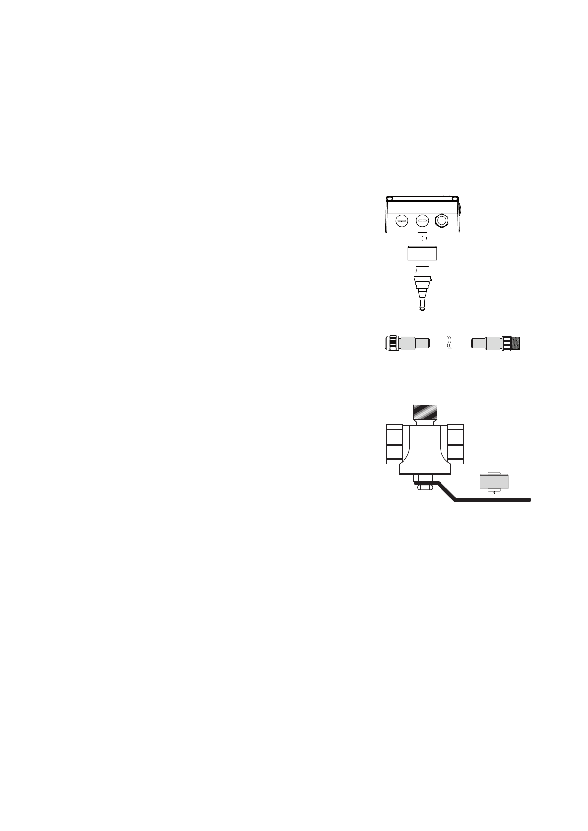
Signal conditioning with optional display
1
The enclosure with the signal conditioning is mounted either on the
measurement probe (model A or B compact) or is remote with a
plugable sensor cable up to 10 meter (33 feet) (model C with remote
probe).
Sensing probe with measurement electronics
2
The interchangeable sensing probe contains the sensor element and
the measurement electronics, in which the data of the factory
calibration is stored. The sensing probe is easy and quickly inter-
changeableintheeld,independentoftheelectronics for the signal
conditioning.After the exchange, the conguration of the outputs is
unchanged.
1
2
3
Sensor cable (only by model C with remote sensing probe)
3
The sensor cable allows for the remote installation, up to 10 meter
(33 feet), of the sensing probe from the housing with the signal conditioning.
Measurment valve with shut-off function
4
The measurement ball valve assembly allows for the easy and reliable
installation within the pipeline. During installation in the pipeline,
observe the required inlet and outlet paths (see page 10). The
nominal size of the measurement ball valve assembly must match the
nominal size of the pipe.
The measurment valve with shut-off function allows for the instalment
and removal of the sensing probe with only interrupting the process
flow for a short moment. The measurement ball valve assembly is
suitable for pressures up to 16 bar (PN16) and available for pipe diameters DN15 (1/2”) to DN50 (2”).
Screw cap
5
The screw cap, with female thread, is screwed in place if the flow
meter is not installed and the pipeline has to be used.
4
5
6
Page 7
3. INSTALLATION
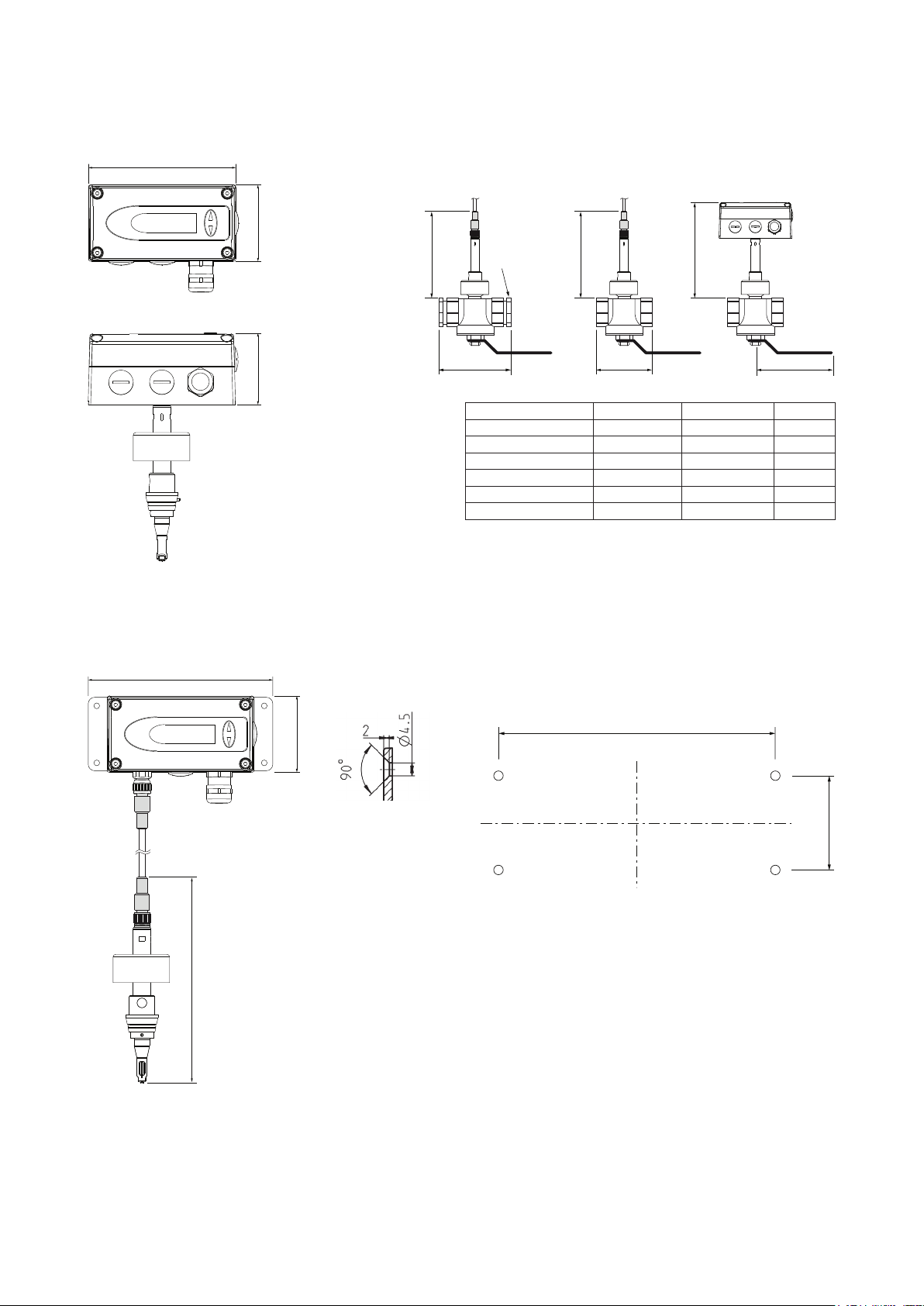
3.1. Mounting dimensions
3.1.1. Model Compact (EE771-A and EE771-B)
115 (4.53)
cable gland
M16x1.5
60 (2.36)
56 (2.2)
Measurement ball valve
Only at DN15:
Reduction
173 (6.81)
Dimensions in mm (inch)
3/4“-1/2“
A A B
Measurment ball valve Thread A B
DN15 R
DN20 Rp or NPT 3/4” 72 (2.83) 92 (3.62)
DN25 Rp or NPT 1” 83 (3.27) 124 (4.88)
DN32 Rp1 1/4" 100 (3.94) 124 (4.88)
DN40 Rp or NPT 1 1/2" 110 (4.33) 147 (5.79)
DN50 Rp or NPT 2” 131 (5.16) 147 (5.79)
dimensions in mm (inch)
Female thread: BSP thread acc. EN 10226 (old DIN 2999) or NPT
173 (6.81)
1/2" 100±8 (3.94±0.32) 92 (3.62)
p
183 (7.2)
3.1.2. Model remote sensing probe (EE771-C)
145 (5.71)
Cross-section
bore hole:
60 (2.36)
cable gland
M16x1.5
207
Drilling Plan:
129 (5.08)
40 (1.57)
The bottom part of the housing is mounted with
4 screws (not in the scope of supply)
Max. screw diameter: 4.5 mm (0.17 inch).
e.g. 4.2 x 38 mm DIN 7938H Screws
7
Page 8

3.2. Determining installation site
•
The installation site should be easy accessible and free of vibrations and shocks
• Observe at least 120 mm (5 inch) clearance above the housing with the signal conditioning, in
order to be able to remove the sensing probe if necessary.
• The ambient temperature should not exceed the value as stated in the specifications (see page 20)
– consider heating by radiation.
• Air purity on the installation site according to ISO 8573-1:2010: at least class 3.4.4
• The fluid should not condense at the installation site. Condensation on the tip of the sensing probe
must be avoided.
• In compressed air systems, the installation must be downstream of the dryer. If there is no dryer, at
least steam trap and suitable filter must be present.
• Observe the direction of the flow by the installation (see page 11).
• Observe the recommended straight pipe lengths up and downstream, in order to warrant the speci-
fied measurement accuracy.
• The flow meter should be installed as far as possible from any flow disturbance. Valves or check-
valves should be installed in a respective distance from the flow meter.
3.2.1. Process pressure
Because of the measuring principle the thermal mass flow meter EE771 is largely independent of the process
pressure and is factory calibrated at a pressure of 7 bar (100 psi).
In order to achieve the highest measurement accuracy, the slight dependence on process pressure can be
compensated for in two ways:
• if the process pressure is stable, by programming the pressure value in the configuration software
(see page 30).
• in case of strong fluctuations of the process pressure (e.g. 3 to 10 bar (40 to 150 psi)) an external
pressure transmitter can be installed and connected to the pressure-compensation input
(see page 31).
In order to install or remove the measurement section the pipeline system should
be depressurized.
8
Page 9
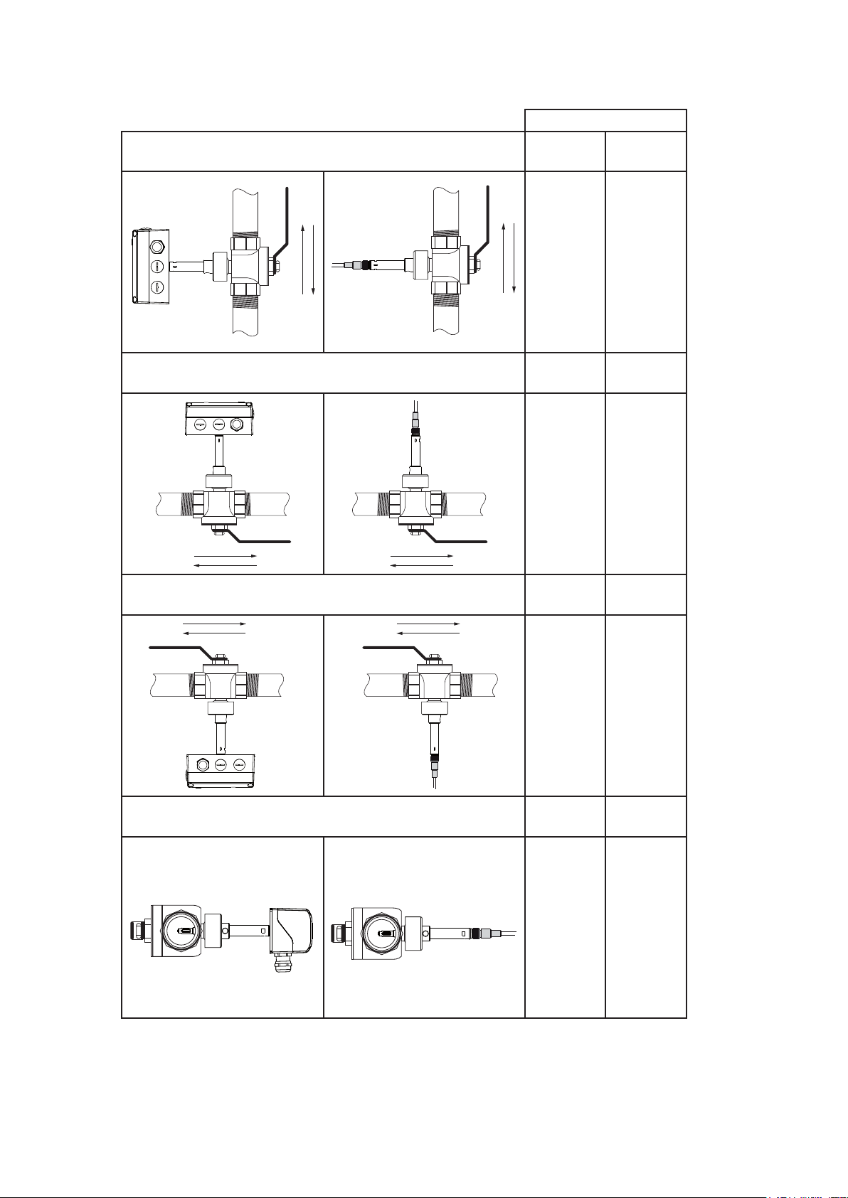
3.3. Installation position
Make sure that the arrow on the tip of the sensing probe is pointing in the direction of the flow.
Model
Vertical Mounting Compact Remote
+ ++
Horizontal Mounting, sensor upwards
Horizontal Mounting, sensor downwards
Horizontal Mounting, sensor across
++ ++
- -
++ ... recommended installation position
+ ..... not recommended if there is vibration on the pipeline
- ...... not recommended
9
+ ++
Page 10
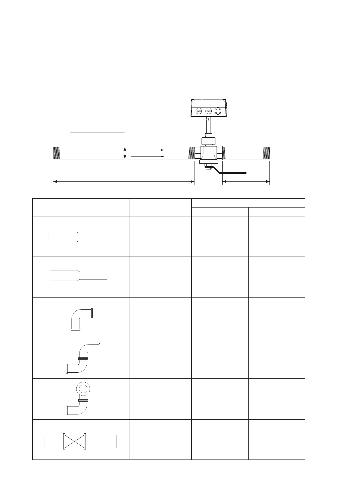
3.4. Required length of straight pipe
The flow meter should be installed as far as possible from disturbances of the flow. The causes for disturbance
of the flow are for instance, reducers, elbows, T-pieces, valves, gate valves, etc. The specified measurement
accuracy can be achieved only when the following straight inlet and outlet pipe lengths are installed:
• The wall thickness of the inlet and outlet pipe should be 2,6 mm.
• The stated values are as a minimum. If possible, allow for greater distances.
• Valves or gate valves should be installed downstream of the flow meter.
• With lighter gases the inlet straight pipe should be longer.
nominal pipe size (DN)
owdirection
straight inlet pipe
Type
Extension 15 x DN 5 x DN
Reduction 15 x DN 5 x DN
90° - elbow 20 x DN 5 x DN
straight outlet pipe
(DN = Nominal Pipe Size)
Straight inlet pipe Straight outlet pipe
Two 90° - elbows,
in one level
Two 90° - elbows,
in two levels, T-piece
Valve, gate valve 50 x DN 5 x DN
10
25 x DN 5 x DN
30 x DN 5 x DN
Page 11

3.5. Assembly of the measurement ball valve
•
All connections to be made with appropriated sealing material on the threads.
• The sealing material should not change the area of the inner cross section of the pipe. It must be
warranted that the connections after installation are free of leaks.
• All fittings must be tested on seal tightness.
• Make sure during the assembly of the measurement section that the arrows on the pipe section
and the measurement ball valve are pointing in the same direction as the flow.
• The recess for the alignment pin must be at the side of the outlet.
recess for
alignment pin
Flow Direction
3.5.1. Assembly without flow meter, but with screw cap instead (blind cap)
In order to use the measurement section without the flow meter, the blind screw cap (in
the scope of supply) must be screwed tight onto the opening of the measurment ball
valve. If not needed the screw cap can be screwed and stored on the handle of the
measurment valve with shut-off function.
3.5.2. Shut off the measurement ball valve
The measurment ball valve assembly allows for the installation and removal of the flow meter within seconds,
with only a very short interruption of the flow.
Never remove the flow meter
or the blind screw cap while
the measurement ball valve
is open.
That is extremely danger-
OPEN
CLOSED
ous!
11
Page 12

3.6. Installation of the flow meter sensing probe
3.6.1. Flow direction
The flow direction is indicated with an arrow on the tip of the probe. Due to the alignment pin is the installation
of the sensing probe in the measurment ball valve only possible in the direction of the flow. After a removal,
the sensing probe will be re-installed in the measurement section in exactly the same position as done at the
factory. Hence, the highest reproducibility is guaranteed.
Flow Direction
3.6.2. Installation of the sensing probe
Make sure that the measurment ball valve is shut off.
Remove transport protection cap of the head of the sensing probe.
•
• Mount the sensing probe in the measurment valve with shut-off function in such a way that the
alignment pin fits in the recess on the measurement ball valve.
• Screw the retainer nut by hand so far that a certain resistance is noticeable.
• Check the correct installation position of the flow meter. The alignment pin must fit in the recess on
the measurment ball valve.
• Tighten the red coloured retainer nut by hand. Tightening by hand should be sufficient. However, if
the seal is not leak tight carefully tighten the nut with an appropriate tool a bit further
• The mechanical installation of the flow meter is therewith completed.
12
Page 13

4. ELECTRICAL CONNECTIONS
Before electrical connections are made turn off the power supply first. If not observed the electronics can be
damaged as a result.
Only a qualified electrotechnical engineer may install the device.
• Unscrew the four screws and remove the cover of the housing.
• The screw terminals are located in the bottom part of the housing.
• For the electrical connection of the flow meter a six-wire cable is needed (e.g. 6 x 1 mm
17))
4.1. Connection diagram
measuring probe
2
(AWG
Modbus data A (=D+) / M-Bus
Modbus data B (=D-) / M-Bus
+
p
4...20mA
I
-
V
or
or
18...30V AC/DC
Screw terminal OUT 1-1 for the analogue output is internally connected with GND.
•
mA
≅
+15V
mA_Input
OUT 1-2
OUT 1-1
OUT 2-1
OUT 2-2
Vcc
GND
optional bus output
Modbus RTU or M-Bus
optional
pressure sensor
signal output 1
analogue- or switching output
signal output 2
switching- or pulse output
supply
• The housing should be grounded to achieve optimal electromagnetic compliance.
4.1.1. Relay and pulse output, internal switching
OUT x-1
OUT x-2
The relay switch and pulse outputs are both potential free.
4.1.2. Connection with optional plug for power supply and outputs (order code Q)
Pin Assignment
1 OUT 2-2
2 OUT 1-2
3 OUT 1-1
4 GND
Connection plug for the
power supply and analogue outputs (rear view of
the terminals)
5 OUT 2-1
6 n.c.
7 Vcc
8 n.c.
13
Page 14

4.2. Bus Output (optional)
4.2.1. M-Bus (Meter-Bus)
The M-Bus (Meter Bus) is a field bus for recording consumption data. Transmission is carried out serially on
a reverse polarity protected two-wire line. The flow meter as M-Bus slave requires a separate supply voltage.
No specific topology (line or star) is prescribed for the cabling. Normal telephone cable of type J-Y(St)Y
Nx2x0.8 mm can be used. A maximum of 250 meters is permitted per segment (primary addressed).
Read-out of the current measurement/consumption data
The following measurement/consumption values are transmitted during a standard query:
• Standard volumetric flow (32 Bit Real)
• Temperature (32 Bit Real)
• Mass flow (32 Bit Real)
• Consumption meter status (32 Bit Real)
• Flow velocity (32 Bit Real)
• Standard volumetric flow (32 Bit Integer)
• Temperature (32 Bit Integer)
• Mass flow (32 Bit Integer)
• Consumption meter status (64 Bit Integer)
• Flow velocity (32 Bit Integer)
The table below shows the package structure of the measurement/consumption data sent by the EE77x transmitter:
Header
68 Start of telegram
4F 4F L-eld(length)
68 Second starting signal
08 C-eld(RSP_UD)
XX A-eld(Adresse)
Start User data
72 CI-eld(variabledatastructure)
XX XX XX XX Identicationnumber
A5 16 Producer (0x16A5 … EUE)
01 Version
09 Medium (9 … compressed air)
XX Access number (continuous)
00 Status
00 00 Signature
Data record 1: Volumenstrom
05 DIF (32 Bit Real)
3E VIF(Volumeowmesseinm³/h)
XX XX XX XX Act. measuring value
Data record 2: Temperature
05 DIF (32 Bit Real)
5B VIF (Temperature in °C)
XX XX XX XX Act. measuring value
Data record 3: Mass ow
05 DIF (32 Bit Real)
53 VIF(Massowinkg/h)
XX XX XX XX Act. measuring value
Data record 4: Consumption meter reading
05 DIF (32 Bit Real)
16 VIF(Volumeinm³)
XX XX XX XX Act. measuring value
Data record 5: Flow rate
05 DIF (32 Bit Real)
7F VIF(manufacturerspecicinm/s)
XX XX XX XX Act. measuring value
Data record 6: Pressure
05 DIF (32 Bit Real)
6B VIF (Pressure in bar)
XX XX XX XX Act. measuring value
Data record 7: Volume ow
04 DIF (32 Bit Integer)
-3
-2
m³)
-3
-3
m³/h)
-2
kg/h)
bar)
°C)
3B VIF(Volumeowin10
XX XX XX XX Act. measuring value
Data record 8: Temperatur
04 DIF (32 Bit Integer)
59 VIF (Temperature in 10
XX XX XX XX Act. measuring value
Datenrecord 9: Mass ow
04 DIF (32 Bit Integer)
51 VIF(Massowin10
XX XX XX XX Act. measuring value
Datenrecord 10: Consumption meter reading
07 DIF (64 Bit Integer)
13 VIF (Volume in 10
XX XX XX XX
XX XX XX XX
Datenrecord 11: Flow rate
04 DIF (32 Bit Integer)
7F VIF(manufacturerspecicin10
XX XX XX XX Act. measuring value
Data record 12: Pressure
04 DIF (32 Bit Real)
68 VIF (Pressure in 10
XX XX XX XX Act. measuring value
End of user data
XX Check sum
16 End of telegram
Akt. consumption data
-2
m/s)
14
Page 15

Secondary addressing
1 2 3 4 5 6 7 8
1 - ON
0 - OFF
1 2 3 4 5 6 7 8
1 - ON
0 - OFF
1 2 3 4 5 6 7 8
1 - ON
0 - OFF
In addition to primary addressing, the EE77x transmitter provides the option of secondary addressing. The
fields of identification number, manufacturer, version and medium are used together as the secondary
address. The exact sequence of the secondary addressing is described in detail in the M-Bus Standard: http://
www.m-bus.com/files/MBDOC48.PDF.
4.2.2. Modbus RTU
The measured values are stored as a 32 Bit float value. Depending on the measurement unit selected, the
measurements are saved in SI or US/GB units. The measurement unit can be changed using the configuration
software.
For resetting the MIN/MAX-Values write 0 to the corresponding write register.
For Modbus protocol setting please see Application Note AN0103 (www.epluse.com/EE771).
Modbus Map:
Register Protocol-
Address
Read Registers (Function Code 0x03 / 0x04) / 32Bit float Value
30026 19 Standardized Flow Nm/s SFPM
30028 1B Standardized Volumetric Flow Nm
30030 1D Temperature °C °F
30032 1F Massflow kg/h kg/h
30034 21 Consumption reading m
30036 23 Pressure bar psi
30261 104 MIN-Value Standardized Flow Nm/s SFPM
30263 106 MAX-Value Standardized Flow Nm/s SFPM
30265 108 MIN-Value Standardized Volumetric Flow Nm
30267 10A MAX-Value Standardized Volumetric Flow Nm
30269 10C MIN-Value Temperature °C °F
30271 10E MAX-Value Temperature °C °F
30273 110 MIN-Value Massflow kg/h kg/h
30275 112 MAX-Value Massflow kg/h kg/h
30277 114 MIN-Value Pressure bar psi
30279 116 MAX-Value Pressure bar psi
Write Registers (Function Code 0x06) / 16Bit integer Value
60261 104 Reset MIN/MAX-Value Standardized Flow
60262 105 Reset MIN/MAX-Value Standardized Volumetric Flow
60263 106 Reset MIN/MAX-Value Temperature
60264 107 Reset MIN/MAX-Value Massflow
60265 108 Reset MIN/MAX-Value Pressure
Measuring Value SI-Unit US/GB-Unit
3
/h SCFPM
3
3
/h SCFPM
3
/h SCFPM
3
ft
4.2.3. Data Transmission
Factory Setting
M-Bus
Baud Rate 2400 9600 600...9600 9600...57600
Data Bits 8 8 8 8
Parity EVEN EVEN None, Odd, Even None, Odd, Even
Stop Bits 1 1 1 or 2 1 or 2
Slave-Address 1 1 0...254 1...247
Factory Setting
Modbus
Adjustable Values
M-Bus Modbus RTU
4.2.4. Addressing
The flow meters are factory-set to address 1. The slave address can be set via switches on the PCB.
Factory Setting:
1 - ON
0 - OFF
1 2 3 4 5 6 7 8
Slave-Address = 1
Slave-Address = 255
1 - ON
0 - OFF
1 2 3 4 5 6 7 8
The address set using
the configurator software
is used.
Dip-Switch for address setting
15
Page 16

5. CONTROL COMPONENTS
V
0
: 323.8 m3/h
Maximal
5.1. Jumper J1 and J2
If the signal output is altered from relay to analogue output or vice versa, Jumper Output 1 has to be relocated.
If the analogue output is altered from a current to a voltage output or vice versa, Jumper Out-1 has to be
relocated.
signal output 1 =
switching output
signal output 1 =
analogue output
Jumper Output 1
Jumper Out-1
analogue output = current signal (e.g. 4-20 mA)
analogue output = voltage signal (e.g 0-10 V)
Modbus RTU only
Line Termination = OFF
Line Termination = ON
150 Ohm parallel to
bus output A and B
Jumper Line Termination
5.2. Digital interface USB (for configuration)
The USB connector is behind the blind screw cap, at the side of the housing.
• remove the blind screw cap with a screwdriver
• plug in the USB connector
Install the configuration software, which is in the scope of supply. The configuration software is
available for downloading as well from our website at www.epluse.com
blind screw cap
USB-cable
5.3. Display / Indicator with keypad (optional)
An optional two-line display is available for the flow meter EE771. The display is an integral part of the cover
of the housing and has two soft-keys for the control of the indicator.
line 1
V
: 1.3 m3/h
0
T : 27.97 °C
pushbutton - UP
pushbutton - DOWN
line 2
16
Page 17

Depending on the configuration of the outputs either the measured values, the status of the relay or the consumption
V
0
: 323.8 m3/h
Maximal
T : 27.97 °C
V
0
: 1.3 m3/h
V
0
: 45.0 m3/h
Rel : 1
V
0
: 323.8 m3/h
Maximal
V
0
: 323.8 m3/h
Maximal
V
0
: 323.8 m3/h
Maximal
is indicated.
measurand
measuring value
unit
V
: 1.3 m3/h
0
T : 27.97 °C
Measurand SI Unit US Unit
v
0 Standardized Flow m/s SFPM
T Temperature °C °F
V
0 Standardized Volumetric
m3/h; m3/min; l/min SCFM; SLPM
Flow
m Massflow kg/h; kg/min; kg/s kg/h; kg/min; kg/s
Q Consumption m
3
3
ft
p Pressure bar psi
5.3.1. Indication of the analogue and pulse output
Line 1 indicates always the configured measurand at output 1. In line 2 the desired measurement value can be
indicated using the UP and DOWN keys.
5.3.2. Indication of the switch output
Line 1 indicates the status of the switch output. In line 2 the desired measurement value can be indicated using the
UP and DOWN keys.
The display shows an inverse image if the relay output is active (relay has switched).
Rel : 1
V0: 1.5 m3/h
Rel : 1
V
: 45.0 m3/h
0
Switch output inactive (relay has not switched) Switch output active (relay has switched)
5.3.3. Indication of the MIN / MAX values
Keep the DOWN key pressed for > 3 sec to indicate the MIN value.
Keep the UP key pressed for > 3 sec to indicate the MAX value.
V
: 1.3 m3/h
0
T : 27.97 °C
MAX value press pushbutton UP >3s
MIN value press pushbutton DOWN >3s
17
Page 18

After that the several different measurement values can be indicated using the UP or DOWN keys.
Keep the DOWN or UP key pressed for > 3 sec to exit the MIN / MAX mode.
Maximal
: 323.8 m3/h
V
0
5.3.4. Reset of the consumption counter or the MIN / MAX value
Keep both the UP and DOWN key pressed for > 3 sec to enter the menu for resetting the consumption counter or the MIN / MAX value. Select the desired menu item by pressing the UP or DOWN key briefly.
Maximal
: 323.8 m3/h
V
0
Press pushbutton UP and DOWN at the same time for >3s
To confirm the selected choice of the menu keep the DOWN or UP key pressed for > 3 sec.
Select menu item “NO” or “EXIT” to cancel without resetting.
> Clear Consumption
Clear Min/Max
Exit
5.3.5. Maximum consumption counter
The maximum consumption counter readout on the display is 999,999,999.0 m
3
or 99,999,999.0 ft3. Then it
shows “LCD maximum”. The internal memory continues counting. The maximum counter reading is 3.4 * 1038
m3. It is possible to read-out the counter reading with the configuration software.
6. ERROR MESSAGES
In case the flow meter is equipped with the optional display, the following error message can be indicated.
ERROR 01: sensing probe is not detected
Cause: the sensing probe is not connect or is defect
Effect: the display indicates “0” for all measurand. The analogue output defaults to the lowest
configured value.
Action: check the head of the sensing probe for visual damage.
check the sensor cable from the sensing probe to the electronics of the signal conditioning.
ERROR 02: the EEprom is defect
Cause: the EEPROM for the storing of the consumption counter and MIN /MAX value is defect.
Effect: the consumption counter and MIN / MAX values are no longer available. All measure-
ment values though are still indicated. The analogue, relay and pulse output are still
functional.
Action: return the flow meter to the manufacturer.
18
Page 19

7. MAINTENANCE
Regular cleaning of the sensor is necessary is used in applications with wet or filthy gases. Cleaning of the sensor
is necessary prior to calibration or evaluation.
7.1. Removal of the sensing probe of the flow meter
•
Shut off the measurement valve with shut-off function
(see page 11).
• Turn off the power supply, remove the cover and disconnect the
power wires on the screw terminal.
• Loose the retainer nut and pull the sensor probe from the meas-
urement section.
Never remove the flowmeter while the measurement ball valve is open.
That is extremely dangerous!
• Operation without the flow meter installed page 11.
7.2. Cleaning of the sensor of the flow meter
Do not use an abrasive cleaning agent, an organic solvent containing halogen or acetone.
• Clean the head of the sensor probe by carefully swirling in warm water of isopropyl alcohol. It is recom-
mended to use isopropyl alcohol if the pollution is crease or oil.
The sensor should not be touch by fingers or solid objects like screwdrivers or brushes!
• Leave the sensor to dry in ambient air.
8. REPLACEMENT PARTS / ACCESSORIES
8.1. Order Code Replacement Sensor
EE771-R-
Hardware Configuration
Model compact ri-le direction od flow right to left A
compact le-ri
remote probe C
Working range low
high
Measuring pipe - DN15 N015
diameter DN20 N020
DN25 N025
DN32 N032
DN40 N040
DN50 N050
Mounting Measurment ball valve K
1)
Plug
cable gland A
1 plug for power supply and outputs Q
1)
only for model A and B
direction od flow left to right B
(0,5...100 Nm/s) or (100...19685 ft/min) L1
(0,5...200 Nm/s) or (100...39370 ft/min) H1
19
Page 20

Order Example Order Example
EE771-R-AL1N025KC12
Model: Compact ri-le
Working range: low
Measuring pipe - diameter: DN25
Mounting: Measurment ball valve
Plug: 1 plug for power supply and outputs
EE771-R-CL1N025K
Model: remote probe
Working range: low
Measuring pipe - diameter: DN25
Mounting: Measurement ball valve
8.2. Order Code Miscellaneous
Measurement ball valve DN15 - Measurement ball valve HA075015
DN20 - Measurement ball valve HA075020
DN25 - Measurement ball valve HA075025
DN32 - Measurement ball valve HA075032
DN40 - Measurement ball valve HA075040
DN50 - Measurement ball valve HA075050
Probe cable (for model C)
cable length 2 m HA010816
5 m HA010817
10 m HA010818
screw cap (blind cap) HA070201
9. TECHNICAL DATA
Measuring value
Flow
Measurand Volumetric flow at standard conditions acc. DIN 1343
P
Measuring range low (L1) high (H1)
DN32: 1,45...289 Nm3/h 0.85...170.0 SCFM 1,45...578 Nm3/h 0.85...340 SCFM
DN40 2,26...452 Nm3/h 1.33...265.9 SCFM 2,26...904 Nm3/h 1.33...531.8 SCFM
DN50: 3,50...700 Nm3/h 2.06...411.8 SCFM 3,50...1400 Nm3/h 2.06...823.6 SCFM
standardizedflow ≤DN50: 0,5...100Nm/s 100...19685 SFPM 0,5...200 Nm/s 100...39370 SFPM
standardized
volumetric flow
Accuracy in air at 7bar (abs) and 23°C (73°F)1) ± (1,5 % of measuring value + 0,5 % of full scale)
Accuracy of temperature compensation ± (0,1 % of measuring value/°C)
Response time t90 typ. 1 sec.
Sample rate 0,1 sec.
Temperature
Measuring range
DN15: 0,32...63 Nm3/h 0.19...37.1 SCFM 0,32...126 Nm3/h 0.19...74.1 SCFM
DN20: 0,57...113 Nm3/h 0.34...66.5 SCFM 0,57...226 Nm3/h 0.34...133 SCFM
DN25:
Accuracy at 20 °C (68 °F) ± 0,7 °C (1.26 °F)
Outputs
Output signal and display ranges are freely scalable
Analogue output voltage 0 - 10 V max. 1 mA
current (3-wire) 0 - 20 mA and 4 - 20 mA R
Switching output potential-free max. 44 VDC, 500 mA switching capacity
Pulse output Totalizator, pulse length: 0,02...2 sec.
Bus output (optional) Modbus RTU or M-BUS (Meter-Bus)
Digital interface USB (for configuration)
Input
Optional pressure compensation 4 - 20 mA (2-wire; 12 V) for pressure sensor
0 = 1013,25 mbar; t0 = 0 °C (273,15 K)
0,90...176 Nm3/h 0.53...103.5 SCFM 0,90...352 Nm3/h 0.53...207.1 SCFM
-20...80 °C (-4...176 °F)
L<500 Ohm
20
Page 21

General
Supply voltage 18 - 30 V AC/DC
Current consumption max. 200 mA (with display)
Temperature range ambient temperature: -20...60 °C
medium temperature: -20...80 °C (-4...176 °F)
storage temperature: -20...60 °C (-4...140 °F)
Nominal pressure up to 16 bar (232 psi)
Humidity no condensation
Medium compressed air or none corrosive gases
Connection cable gland M16x1,5 (optional connector M12x1 8pol.)
Electromagnetic compatibility EN61326-1 EN61326-2-3
Industrial Environment
Material housing metal (AlSi3Cu)
probe stainless steel
sensor head stainless steel / glass
measurement ball valve brass
Housing protection class IP65 / Nema 4
1) The accuracy statement includes the uncertainty of the factory calibration with an enhancement factor k=2 (2-times standard deviation). The accuracy was
culated in accordance with EA-4/02 and with regard to GUM (Guide to the Expression of Uncertainty in Measurement).
9.1. Factory setting of outputs
SI-Unit
Analogue output
[0...10 V / 0(4)...20 mA] from to unit
low (L1) high (H1)
standardized DN15: 0 60 120 Nm
volumetric flow DN20: 0 110 220 Nm
DN25: 0 175 350 Nm3/h
DN32: 0 285 570 Nm3/h
DN40: 0 450 900 Nm3/h
DN50: 0 700 1400 Nm
mass flow DN15: 0 75 150 kg/h
DN20: 0 140 280 kg/h
DN25: 0 220 440 kg/h
DN32 0 360 720 kg/h
DN40: 0 570 1140 kg/h
DN50: 0 890 1780 kg/h
standardized flow
temperature all Ø -20 80 80 °C
≤DN50 0 100 200 Nm/s
(-4...140 °F)
3
/h
3
/h
3
/h
Switching output [switching point/hysteresis]
volumetric flow DN20 90/9 180/18 Nm3/h
DN25: 150/15 300/30 Nm3/h
DN32: 230/23 460/46 Nm3/h
DN40: 360/36 720/72 Nm
DN50: 560/56 1120/112 Nm3/h
mass flow DN15: 60/6 120/12 kg/h
DN20: 110/11 220/22 kg/h
DN25: 200/20 400/40 kg/h
DN32: 290/29 580/58 kg/h
DN40: 460/46 920/92 kg/h
DN50: 700/70 1400/140 kg/h
standardized flow
temperature
Pulse output pulse-value = 1 m
standardized DN15 50/5 100/10 Nm3/h
3
≤DN50 80/8 180/18 Nm/s
all Ø 30/3 70/7 °C
3
pulse-duration = 0,1 sec.
/h
21
Page 22

US-Unit
Analogue output [0...10 V / 0(4)...20 mA] from to unit
low (L1) high (H1)
standardized DN15: 0 35 70 SCFM
volumetric flow DN20: 0 60 120 SCFM
DN25: 0 100 200 SCFM
DN32: 0 165 330 SCFM
DN40: 0 260 520 SCFM
DN50: 0 410 820 SCFM
mass flow DN15: 0 75 150 kg/h
DN20: 0 140 280 kg/h
DN25: 0 220 440 kg/h
DN32 0 360 720 kg/h
DN40: 0 570 1140 kg/h
DN50: 0 890 1780 kg/h
standardized flow
Temperatur alle Ø -4 176 176 °F
Switching output [switching point/hysteresis]
volumetric flow DN20 50/5 100/10 SCFM
DN25: 80/8 160/16 SCFM
DN32: 130/13 260/26 SCFM
DN40: 210/21 420/42 SCFM
DN50: 330/33 660/66 SCFM
mass flow DN15: 60/6 120/12 kg/h
DN20: 110/11 220/22 kg/h
DN25: 200/20 400/40 kg/h
DN32: 290/29 580/58 kg/h
DN40: 460/46 920/92 kg/h
DN50: 700/70 1400/140 kg/h
standardized flow
temperature
standardized DN15 30/3 60/6 SCFM
≤DN50 0 20000 40000 SFPM
≤DN50 15000/1500 30000/3000 SFPM
all Ø 90/9 150/15 °F
Pulse output pulse-value = 1CF pulse-duration = 0.1 sec.
CONFIGURATION SOFTWARE
LIMITED LIABILITY
E+E Elektronik shall not be held liable for any damages or consequential damages (for example, but not
restricted to, loss of earnings, interruption of business, loss of information and data or any other financial
losses) resulting from the installation, use or impossibility of use of an E+E Elektronik software product and
any associated support services or non-performance of support services.
1. General
The configuration software can be downloaded free of charge at www.epluse.com/ee771
The configuration software, allows for a user-friendly adaptation of the flow meter to the application. In addition, the measurement values for flow and temperature can be calibrated / adjusted.
The system requirements for the installation and execution of the software are:
• Windows XP with SP3, Windows Vista or Windows 7
• .NET framework 3.5 with SP1
• USB 2.0 interface
During setup there will be no installation of .NET Framework 3.5 SP1 – if the required version is not already
installed on the computer the following error message will appear at the start of the configuration software.
.NET Framework 3.5 SP1 can be installed using Windows Update.
22
Page 23

2. Installation
In order to set up a smooth installation of the configuration software of the EE771, admin authorization for the
personal computer is required.
• During installation of the software the EE771 should NOT be connected with the USB cable to the
computer.
• Wit Setup.exe the InstallShield-Wizard for the EE771 configurator will be started.
• Follow the instructions on the screen to install the software.
At first, the configuration software will be installed and then the installation of the USB driver activated – except
if the user has defined that USB setup is disabled.
The USB driver will be automatically installed the moment the first connection is made with the EE771.
The appearing dialog boxes can be dealt with the settings “No. do not download driver from the internet” and
“Install the hardware automatically”.
If the EE771 configuration software and the USB driver are installed correctly, and the EE771 is connected
via the USB interface with the personal computer, a connection “Silicon Labs C210x USB to UART Bridge”
should have been created in the device manager.
See: Start => Settings => Control Panel => System => Hardware => Device
Manager
2.1. Configuration of the USB Interface (VirtualCOM)
After the startup of the software, the correct VirtualCOM interface for the
USB driver must be configured
The number for the used USB interface can be found under:
Start => Settings => Control Panel => System => Hardware => Device
Manager
The setting is done under menu “Extras” and menu item “Optional extras
...”
23
Page 24

Select the COM-port number as shown in the device manager.
These settings are done only once and at the first start of the configuration software. The settings are stored
for future use.
3. User Interface
4
1
2
3
1
3
2
Basic information:
After retrieving the data from the transmitter, the basic information of the device is shown here.
Status message:
Here are the messages shown about the status and other information.
Input screen:
Input screen for the configuration or adjustment of the flow meter.
4
Menu tool bar:
Selection of menu items.
24
Page 25

4. Menu toolbar
4.1. File
Delete status message deletes the status messages.
Exit closes the configuration software.
4.2. Transmitter
Read reads the actual configuration of the transmitter.
Send uploads the ‘new’ configuration to the transmitter.
The following settings are uploaded to the transmitter
• Units
• Output 1
• Output 2
• Display mode
• Pressure transmitter
Prior to uploading the ‘new’ configuration to the transmitter, a dialog box will show a summary of the
changes. Click on the button ‘OK’ and the configuration will be uploaded to the transmitter; click
‘Cancel’ to cancel the operation.
4.3. Extras
Configurations of the VirtualCOM- interface (see page 23).
5. Input Screen
5.1. Output 1, Output 2
In this screen the actual settings of the transmitter for the output 1 and 2, resp. relay 1 and 2 are shown. The
user can alter and upload these settings to the transmitter, together with other changes of the configuration.
5.1.1. Output mode
Here the mode of signal output can be determined.
Output 1: analogue or switch (relay) output
Output 2: switch (relay) or pulse output
NOTE:
In case the mode of output 1 is changed, the Jumper J1 on the board of the signal conditioning electronics has to
be relocated as well (see page 25)
5.1.2. Measurand
Here is determined which measurand will be represented at the particular output.
5.1.3. Units
Choice of the engineering units of the selected measurand in either SI- (m/s; °C; m3/h) or US-units
(SFPM; °F; SCFM).
25
Page 26

NOTE:
The setting “Units” on the tabs for Output 1 and Output 2 are in sync with each other. If the units are changed
on one of the output tabs, automatically the units on the other output tab are changed accordingly.
5.1.4. Output mode – analogue
Within the limits of measurement range and the scaling of the output, the analogue output can be freely configured and scaled. Either a standard output signal (0 – 5 V, 0 – 10 V, 0 – 20 mA, 4 – 20 mA) can be selected
or a user defined range for the current / voltage output (e.g. 1 – 9 V).
NOTE:
In case the analogue output is changed (from current to voltage or vice versa), the Jumper J2 on the board
of the signal conditioning electronics has to be relocated as well (see page 25).
5.1.5. Output mode – switch (relay)
In the field for the “Switch-mode”, one can select “Hysteresis” or “Window”.
The field for “Type” is to determine the switch action of the relay, NO = Normally Open (activate to close), NC
= Normally Close (activate to open).
Under “Measuring range” in the field “From” the low value of the measuring range can be entered and in the
field “To” the high value.
The hysteresis of the set point is entered as a percentage of the
measuring range.
[measuring range] = high measuring value – low measuring value
e.g. hysteresis
set point = 500 Nm3/h and reset point is 450 Nm3/h
Hysteresis = 50 Nm3/h = 0.5 % of measuring range
Hysteresis
Nm3/h
When the measurement value reaches set point 1, the relay will
be activated. The value at the reset point is the value at set point 1
minus the hysteresis.
set point 1
e.g. set point 1 = 100 Nm3/h and the hysteresis 5 Nm3/h.
the relay switches at 100 Nm3/h. The reset point is at 96 Nm3/h.
NO (activate to close)
NC (activate to open)
Hysteresis
1
0
1
0
t
Hysteresis = 5 Nm3/h = 5% of the measuring range
26
Page 27

Window
Nm3/h
The relay is activated as long as the measuring value is
between the values of set point 1 and set point 2.
The hysteresis of each set point is fixed at 0.2% of the meas-
set point 1
set point 2
uring range.
e.g.: set point 1 = 100 Nm3/h; set point 2 = 80 Nm3/h;
hysteresis of each set point is 1 Nm3/h (0.2% of 500 Nm3/h)
t
NO (activate to close)
NC (activate to open)
1
0
1
0
3
80 Nm
/h = set point 2
100 Nm3/h = set point 1
99 Nm3/h = set point 1 - hysteresis
79 Nm3/h = set point 2 - hysteresis
5.1.6. Output mode – pulse
If output 2 is configured for pulse, the measurand can be consumption only. Under “Pulse”, the duration of the
pulse and the pulse value (Significance level of pulse) can be freely configured.
Volume Flow [m3/h] Number of Pulses
3
/Pulse]
=
HourPulse Value [m
The duration of the pulse can be set between 0.02 and 2 seconds.
3
e.g. Duration of pulse = 100ms; one pulse for each Nm
consumed
The pulse – interval – ratio must be at least 1 : 2, meaning that the duration of the pulse interval must be at
least twice the duration of the pulse itself.
OUT 2
≥ 2 s
1/3 min. 2/3
t
Calculation of the minimum “pulse value” or the maximum “pulse duration”.
IMPW_MIN = NORMV_MAX [m3/h] * IMPL [s] / 1200
IMPL_MAX = IMPW [m3] * 1200 / NORMV_MAX [m3/h]
IMPW pulse value [m
IMPL pulse length (duration) [s]
IMPW_MIN minimum pulse value [m3]
IMPL_MAX maximum pulse length (duration)
NORMV_MAX expected maximum volume flow (Nm3/h)
3
]
5.2. Minimum flow shutdown
The minimum flow shutdown is switched on and off using the “active” checkbox.
Iftheoutputsignalis≤thantheset“Shutdownvalue”,theflowmeterissues0ontheanalogueoutput.
27
Page 28

5.3. Display
If an optional display is installed, at the tab Display the following items can be entered:
Drop-down input field “Display-Mode”
• Single spaced
• Double spaced (default)
Checkbox “Backlight”
• Checked = ON
• Unchecked = OFF
In the input field
“Description (free text), a
user specific name (max.
16 characters) for the
transmitter can be
entered.
e.g.: HALL 1
With the button “send” only the description will be uploaded to the transmitter.
5.4. Adjustment
The user can perform an adjustment for the measurands normflow and temperature in air.
The configuration software distinguishes between a 1-point and a 2-point adjustment automatically, depending
on how many reference points for adjustments are entered.
The values entered for the customer’s adjustment are stored in the electronics of the sensing probe and are
therefore not lost if the electronics of the signal conditioning are replaced (see page 6)
If the checkbox “Performing customer-adjustment” is checked, the adjustment mode will be activated and the
actual measuring value in the set interval automatically retrieved from the flow meter (transmitter).
NOTE: At first change to “Calibration gas” in the tab “Process parameters”.
While the customer-adjustment is active all other pages, functions and commands are deactivated.
In the field “Adjustment” the measurand to be adjusted is selected.
In the field “Measuring value” the actual measurement value of the transmitter is indicated.
The update-interval can be set.
In the field “Reference value” the measurement value of the standard is entered.
After clicking the button “send” a control dialog box appears in which the values can be corrected if needed.
Then the reference value will be uploaded to the flow meter (transmitter) and is the adjustment procedure
complete.
The reference point of the customer-adjustment must be within the determined measuring range.
The customer-adjustment results in a slight rotation of the characteristic line, in such a way that the measurement deviation at the upper and lower adjustment points equals zero.
The configuration software determines, depending on its position, if it is an upper or lower adjustment point.
5.4.1. 1-point adjustment
lower adjustment point upper adjustment point
possibility 1 0 - 50% of measuring range 100% of measuring range
possibility 2 0% of measuring range >50 - 100% of m.r.
28
m.r. ... measuring range
Page 29

upper adjustment point at 80% of measuring range
10% 20% 30% 40% 50% 60% 70% 80% 90% 100%
lower adjustment point automatically at 0% of m.r.
lower adjustment point at 20% of measuring range
upper adjustment point automatically at 100% of m.r.
100%
90%
80%
70%
60%
50%
40%
output signal
30%
20%
10%
characteristic line before adjustment
characteristic line after adjustment
selected adjustment point
10% 20% 30% 40% 50% 60% 70% 80% 90% 100%
measuring range
100%
90%
80%
70%
60%
50%
40%
output signal
30%
20%
10%
characteristic line before adjustment
characteristic line after adjustment
selected adjustment point
measuring range
5.4.2. 2-point adjustment
With a 2-point adjustment procedure the lower adjustment point must be between 0 and 40% of the measuring
range, and the upper adjustment point between 60 and 100% of the measuring range. If the adjustment point is
between 40 and 60% of the measuring range, automatically a 1-point adjustment procedure will be executed instead.
lower adjustment point upper adjustment point
possibility 1 0 - <40% of m.r. 60 - 100% of m.r.
possibility 2 40 - <50% of m.r. 100% of m.r.
possibility 3 0% of m.r. 50 - <60% of m.r.
lower adjustment point at 10% of measuring range
upper adjustment point at 90% of measuring range
100%
90%
80%
70%
60%
50%
40%
output signal
30%
20%
10%
characteristic line before adjustment
characteristic line atfer adjustment
10% 20% 30% 40% 50% 60% 70% 80% 90% 100%
measuring range
29
Page 30

5.4.3. Reset to factory settings
Customer-adjustment can be reset to the factory settings by checking the appropriate checkbox and subsequently clicking the “reset” button.
5.5. Measuring values overview
The tab measuring values provides an overview of the retrieved actual measurement values of the flow
meter (transmitter). Clicking on “Fetch values” will retrieve the actual measurement and MIN / MAX values for
flow, volume flow, temperature, mass flow and pressure (only if a pressure transmitter is connected) from the
transmitter – additional the reading of the consumption meter is retrieved as well.
Checking the “Polling” checkbox will retrieve the measuring data from the transmitter at the selected interval.
5.5.1. Reset of the MIN / MAX values
The MIN/ MAX values of each measurand, as stored in the flow meter (transmitter), can be reset by checking
the appropriate checkbox and subsequently clicking the “Clear MIN / MAX” button.
5.5.2. Reset of the consumption counter (totalizer)
The reading of the consumption meter can be reset by clicking the “Reset meter” button.
5.6. Setting up Process Parameters
In the tab Process Parameters you can change the Process gas (medium) and set the pressure compensation
5.6.1. Change the Process Gas
NOTE: This function is only active if the flow meter for a medium different from air has been ordered (see
order code Medium in the data sheet)
Calibration-Gas: Is the gas (medium) in which the flow meter was calibrated in the factory. Unless otherwise
specified, the flow meter is calibrated at the factory always in air.
Process-Gas: Is the gas (medium) in the measured process. The adjustable process gases are set at the
factory and can be selected from a list.
The flow meter is factory set to the ordered gas (medium).
If the setting for the process-gas modified or changed between calibration- and process gas, the changed
setting has to be sent to the transmitter. Use “send data to the transmitter and read ...” button.
The “active gas” to which the flow meter is set, you can see in the field basic information.
30
Page 31

5.6.2. Changing the standard conditions
The flow meter is factory-set to standard conditions conforming to DIN 1343.
Factory setting: P
The corrected volume flow measured value is calculated in line with the standard conditions set.
5.6.3. Pressure compensation
The flow meter is factory-adjusted to 7 bar (abs). At an operating pressure other than 7 bar (abs), the error
can be corrected via the pressure coefficient of +0.5% of the measured value per bar by entering the actual
system pressure.
The “Send” button is used only to send the process pressure to the transmitter.
= 1013.25 mbar, t0 = 0°C (273.15 K)
0
5.7. External pressure transmitter for pressure compensation
In order to achieve the highest accuracy, the input from an external pressure transmitter will be very useful if
the pressure fluctuates strongly (e.g. 3 to 10 bar (45 to 150 psi)). An absolute pressure transmitter with a
2-wire loop powered 4 – 20 mA output should be used.
On the tab “Pressure transmitter” the measuring range can be entered.
5.8. Bus configuration
If the flow meter is equipped with an optional bus module, the data transfer rate and the network address can
be set on the “Bus configuration” tab.
The network address set is only used when the dip switches on the flow meter PCB are set to 255 (see page 14).
31
Page 32

HEAD OFFICE:
E+E ELEKTRONIK Ges.m.b.H.
Langwiesen 7
A-4209 Engerwitzdorf
Austria
Tel: +43 7235 605 0
Fax: +43 7235 605 8
info@epluse.com
www.epluse.com
SALES OFFICES:
E+E CHINA / BEIJING
Tel: +86 10 84992361
info@epluse.cn www.epluse.cn
E+E CHINA / SHANGHAI
Tel: +86 21 61176129
info@epluse.cn www.epluse.cn
E+E GERMANY
Tel: +49 6172 13881 0
info@epluse.de www.epluse.de
E+E FRANCE
Tel: +33 4 7472 35 82
info@epluse.fr www.epluse.fr
E+E ITALY
Tel: +39 02 2707 8636
info@epluse.it www.epluse.it
E+E KOREA
Tel: +82 31 732 6050
info@epluse.co.kr www.epluse.co.kr
E+E USA
Tel: +1 508 530 3068
office@epluse.com www.epluse.com
 Loading...