

Page 1

EE75 Series
Air / Gas Velocity
Transmitter
BA_EE75_e_12// technical data subject to change // 192310
Manual
Hardware and Software
Page 2

E+E Elektronik® Ges.m.b.H. doesn't accept warranty and liability claims neither
upon this publication nor in case of improper treatment of the described products.
The document may contain technical inaccuracies and typographical errors. The
content will be revised on a regular basis. These changes will be implemented in
later versions. The described products can be improved and changed at any time
without prior notice.
© Copyright E+E Elektronik
®
Ges.m.b.H.
All rights reserved.
USA
FCC notice:
This equipment has been tested and found to comply with the limits for a Class B digital device, pursuant to part 15 of the FCC Rules. These limits are designed to provide reasonable protection against
harmful interference in a residential installation. This equipment generates, uses and can radiate
radio frequency energy and, if not installed and used in accordance with the installation manual, may
cause harmful interference to radio communications. However, there is no guarantee that interference will not occur in a particular installation. If this equipment does cause harmful interference to
radio or television reception, which can be determined by turning the equipment off and on, the user
is encouraged to try to correct theinterference by one or more of the following measures:
- Reorient or relocate the receiving antenna.
- Increase the separation between the equipment and receiver.
- Connect the equipment into an outlet on a circuit different from that to which the receiver is connected.
- Consult the dealer or an experienced radio/TV technician for help.
Caution:
Any changes or modifications not expressly approved by the party responsible for compliance could
void the user's authority to operate this device.
CANADIAN
ICES-003 notification:
This Device B digital apparatus complies with Canadian ICES-003.
Cet appareil numérique de la classe B est conforme à la norme NMB-003 du Canada.
1
Page 3

HARDWARE
CONFIGURATION
SOFTWARE
TABLE OF CONTENTS
1. GENERAL 3
1.1 Symbol assertion 3
1.2 Safety instructions 3
1.3 Environmental information 3
2. PRODUCT DESCRIPTION 3
3. INSTALLATION 4
3.1 Installing the housing 4
3.2 Mounting Model A (wall mounting) 4
3.3 Mounting Model B (duct mounting) 4
3.3.1 Mounting with brackets 4
3.3.2 Mounting with a flange 4
3.4 Mounting Model C (remote probe) 5
3.4.1 Installing the housing 5
3.4.2 Installing the probe 5
3.5 Mounting Model E (remote probe, pressure-tight to 10 bar / 145psi) 5
3.5.1 Installing the housing 5
3.5.2 Installing the probe 5
4. ELECTRICAL CONNECTIONS 7
4.1 Connection diagram 7
4.2 Connection diagram with plug connections (optional) 7
4.3 Assignment USB - interface cable 7
5. OPERATING COMPONENTS 8
5.1 Circuit board 8
5.2 Jumpers for setting the output signal 8
5.3 Jumpers for setting the velocity response time 8
5.4 Display module with buttons (optional) 9
6. VELOCITY/TEMPERATURE CALIBRATION 10
6.1 Selecting the appropriate calibration method (1-point or 2-point calibration) 10
6.1.1 General information on 1-point v/T calibration 10
6.1.2 General information on 2-point v/T calibration 11
6.2 Velocity calibration 11
6.2.1 Calibration procedure using configuration software 11
6.2.2 Calibration procedure using buttons on the display module (optional) 11
6.3 Temperature calibration 11
6.3.1 Calibration procedure using configuration software 11
6.3.2 Calibration procedure using buttons on the display module (optional) 11
6.4 Resetting to factory calibration 12
6.4.1 Resetting v/T to factory calibration 12
6.4.2 Resetting v to factory calibration 12
6.4.3 Resetting T to factory calibration 12
7. SELF-HELP / MAINTENANCE 13
8. REPLACEMENT PARTS / ACCESSORIES 13
9. TECHNICAL DATA 13
1. GENERAL INFORMATION 14
2. INSTALLATION 14
2.1 Installing the USB-interface 14
3. MENU ITEMS 16
3.1 File 16
3.2 Help 16
4. EE75 CONFIGURATOR 16
4.1 Start 16
4.2 Analog 17
4.3 Display 17
4.4 Response Time 17
4.5 Cross Section 18
4.6 Probe Cable 18
4.7 Switching Off 19
4.8 Media Correction 19
4.9 Calibration 19
4.9.1 Information on 1-point v/T calibration 20
4.9.2 Information on 2-point v/T calibration 20
4.9.3 v calibration procedure using the configuration software 20
4.9.4 T calibration procedure using the configuration software 20
4.9.5 Activating factory calibration 20
4.10 Measuring Values 21
4.11 Information 21
2
Page 4
1. GENERAL
This manual forms part of the scope of supply and serves to ensure proper handling and optimum functioning of the instrument.
Consequently, it is essential to read the manual before commissioning.
The manual is also to be brought to the attention of any person involved in transport, setup,
operation, maintenance or repair.
This manual must not be used for competition purposes without the written consent of
E+E Elektronik® and must not be forwarded to third parties.
Copies for personal use are permitted.
All information, technical data and illustrations contained in this manual are based on the information available at the time of publication.
1.1 Symbol assertion
This symbol indicates a safety instruction.
Safety instructions must always be followed. Failure to do so can result in injuries or
damage, for which E+E Elektronik® accepts no liability.
This symbol indicates a note.
These notes should be observed to achieve optimum functioning of the equipment.
1.2 Safety instructions
•
Excessive mechanical stress and improper use must be avoided.
• As the sensor element is sensitive to electrostatic discharge (ESD), appropriate
protective measures should be taken when touching it.
• Installation, electrical connection, maintenance and commissioning must only be
carried out by qualified personnel.
1.3 Environmental information
E+E Elektronik® products are developed with due consideration to all major environmental issues. Bearing this in mind, care should also be taken to avoid polluting the environment when
disposing of equipment. When disposing of the transmitter, the individual
components must be sorted according to type.
Electronic components must be kept together and disposed of in the proper manner for electronic scrap.
Hardware
2. PRODUCT DESCRIPTION
The EE75 series velocity transmitters were developed to obtain accurate measuring results over
a wide range of velocities and temperatures.
They have a robust metal housing to protect them against possible damage in rough
industrial environments and come in four different models, providing a comprehensive range of
mounting options:
• Model A for wall mounting
• Model B for duct mounting
• Model C with remote probe
• Model E with remote probe, pressure-tight to 10 bar (145psi)
3
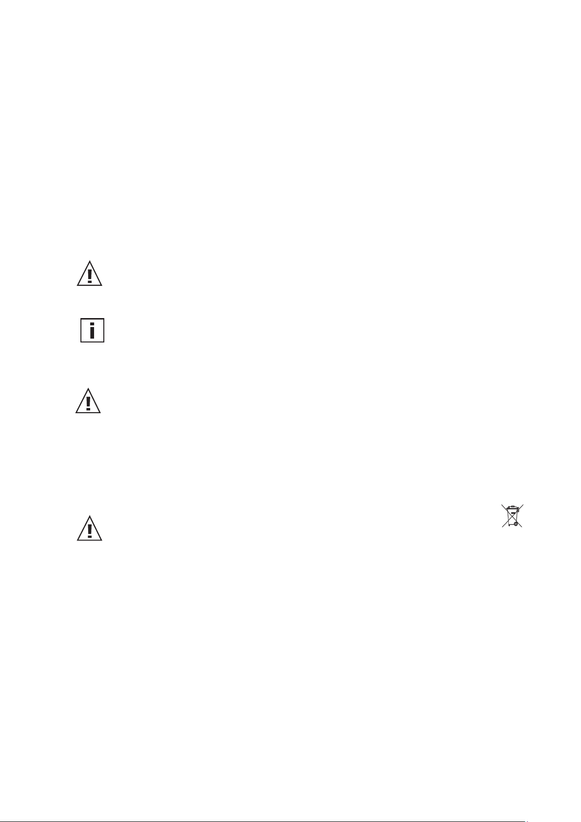
Page 5
all dimensions in mm
3. INSTALLATION
Before starting the installation please make sure that the upper and lower
modules of the housings are not mixed up! Only with identical serial
numbers the function of the transmitter can be guaranteed within the
specifications (see chapter 9. “Technical Data”).
3.1 Installing the housing
145 (5.7”)
115 (4.5”)
40 (1.6”)
129 (5.1”)
cross-section of bore:
2 (0.1”)
90°
∅4.5
(0.2”)
60 (2.4”)
1. On delivery, the two mounting brackets (on the left and right of the
housing base plate) are attached to the lower part of the housing with
two screws each, facing inwards. For installation, the brackets can be
swung out and screwed down (see drawing).
2. The dimensions of the mounting holes are as shown in the adjacent
drawing.
3. The bottom part of the housing is fitted using 4 screws (not included).
Max. screw diameter 4.5 mm
(0.18”), for example 4.2 x 38mm (0.17 x 1.5”)
- DIN 7983H screws.
4. Connecting the transmitter (see Section 4 - Electrical Connections)
5. Lift the upper part of the housing into position and screw it into place
using the four Allen screws included (Allen key provided).
3.2 Mounting Model A (wall mounting)
selected probe length
∅8
(0.3”)
selected probe length
∅8
(0.3”)
12 (0.5”)
bore diameter: 5.1 (0.2”)
12 (0.5”)
2 (0.1”)
sealing
rubber
See Section 3.1 - Installation of the housing
3.3 Mounting Model B (duct mounting)
There are two types of duct mounting:
3.3.1 Mounting with brackets
See Section 3.1 - Installation of the housing
OR:
3.3.2 Mounting with a flange
The stainless steel mounting flange allows for the transmitter to
be mounted on the outside wall of the duct in which the
measurement takes place and adjusted to any insertion depth.
80
(3.1”)
Hardware
4
Page 6
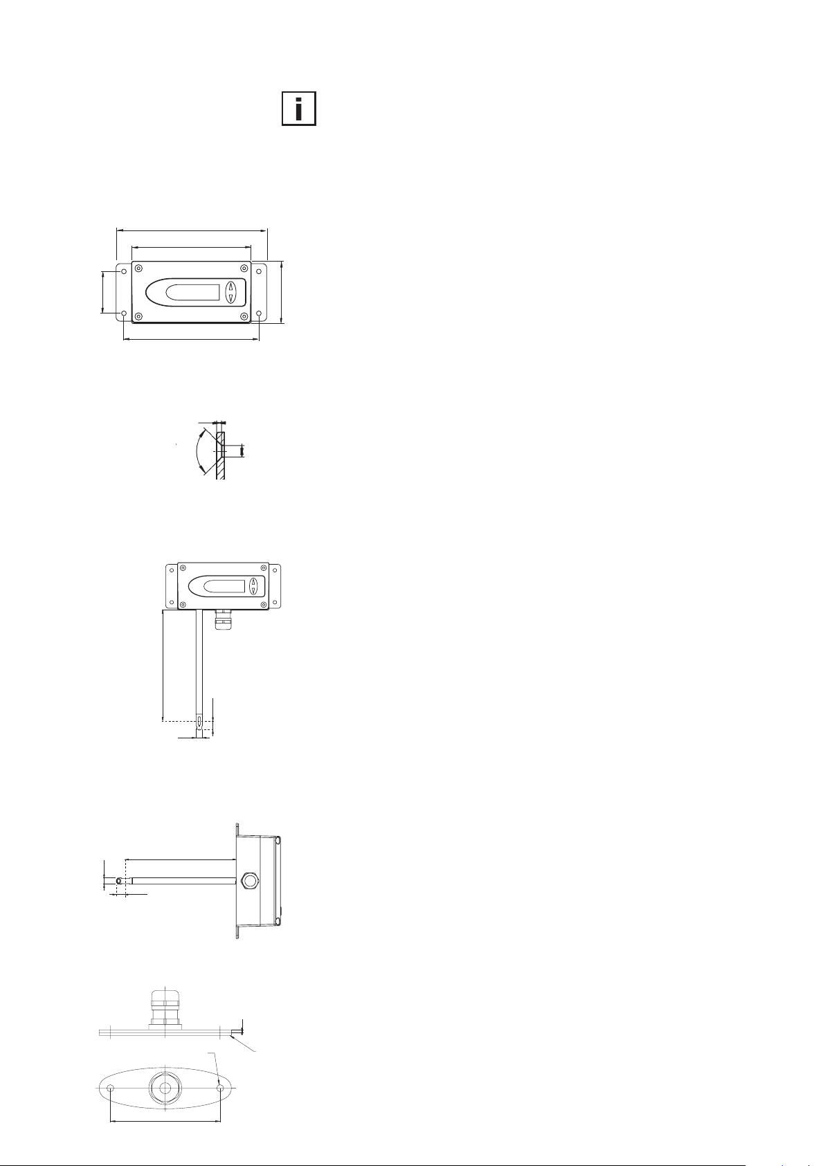
selected probe length
3.4 Mounting Model C (remote probe)
∅8
(0.3”)
12
(0.5”)
selected probe length
∅8
(0.3”)
12
(0.5”)
3.4.1 Installing the housing
See Section 3.1 - Installing the housing
3.4.2 Installing the probe
See Section 3.3.2 - Mounting with a flange
3.5 Mounting Model E (remote probe,
pressure-tight to 10 bar
/ 145psi)
3.5.1 Installing the housing
See Section 3.1 - Installing the housing
3.5.2 Installing the probe
General safety instructions for installation using pressuretight movable screw connections
As the sensing probe can be exposed to very high pressures in the
measuring environment, there is a risk of sudden, unintentional expulsion of the probe during or after improper installation. Special care
should therefore be taken when working on or in the vicinity of the
sensing probe. Do not, under any circumstances, bend directly over the
probe.
When installing the sensor probe, be careful not to damage the surface
of the sensing probe.
This could damage the seals (resulting in leakage and pressure loss)
or cause problems when removing the probe (may get stuck).
Before installing the sensing probe, make sure it is free from any impurities such as grease or dirt.
clamping
ring
1/2” ISO
or NPT
bore ∅
> 9.2mm (0.4”)
shut-off
valve
Hardware
lock nut
sealing ring
shut-off
valve
Installing the probe
There should be a shut-off valve on both sides of the probe insert when
installing the probe. This makes it easy to remove the transmitter for
maintenance and calibration.
1. Install the probe with the shut-off valves closed.
2. Insert the sensor probe into the process.
3. To ensure the probe is installed securely, the lock nut must be
tightened to a specified torque of 10 Nm.
If no torque spanner is available, tighten the lock nut by hand as far
as possible and then turn it a further ~ 90° with an appropriate
open-ended spanner.
An inadequate torque results in a low tension force (fixing
force) on the clamping sleeve. This brings with it a risk of injury
due to sudden expulsion of the sensing probe. An excessive
torque can lead to permanent deformation of the clamping
sleeve and sensing probe, making removal and re-installation
more difficult or even impossible.
Removing the probe
1. If the sensor probe is installed in a pressure chamber, make sure
that the pressure in the chamber and the ambient pressure are
in equilibrium before removing the probe.
2. Hold the sensing probe/housing firmly. (Attention: Do not bend the
connection cable)
3. Slowly loosen the lock nut using a spanner (spanner width 24).
4. The entire probe can now be removed.
5
Page 7
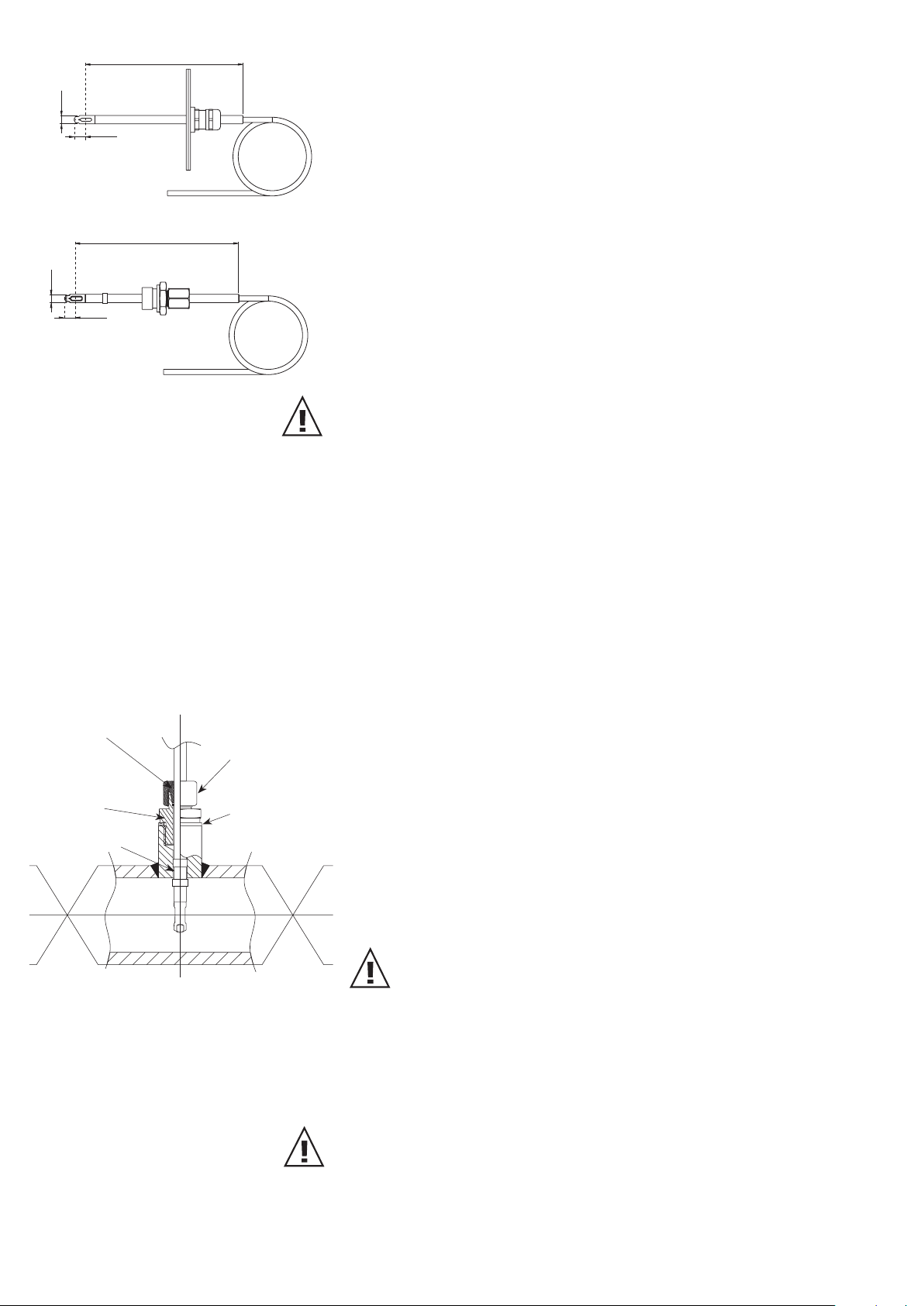
General installation instructions:
Scaling the insertion depth on the probe
The insertion depth can be read off directly on the probe. The depth is
measured from the centre of the velocity measuring slot (= middle of
x
scale
the sensor). The scaling on the probe has an offset of 30mm (1.2”). This
allows for the insertion depth "X" (= distance between middle of sensor
and mounting plate) to be read off directly above the screwed cable
gland (see sketch).
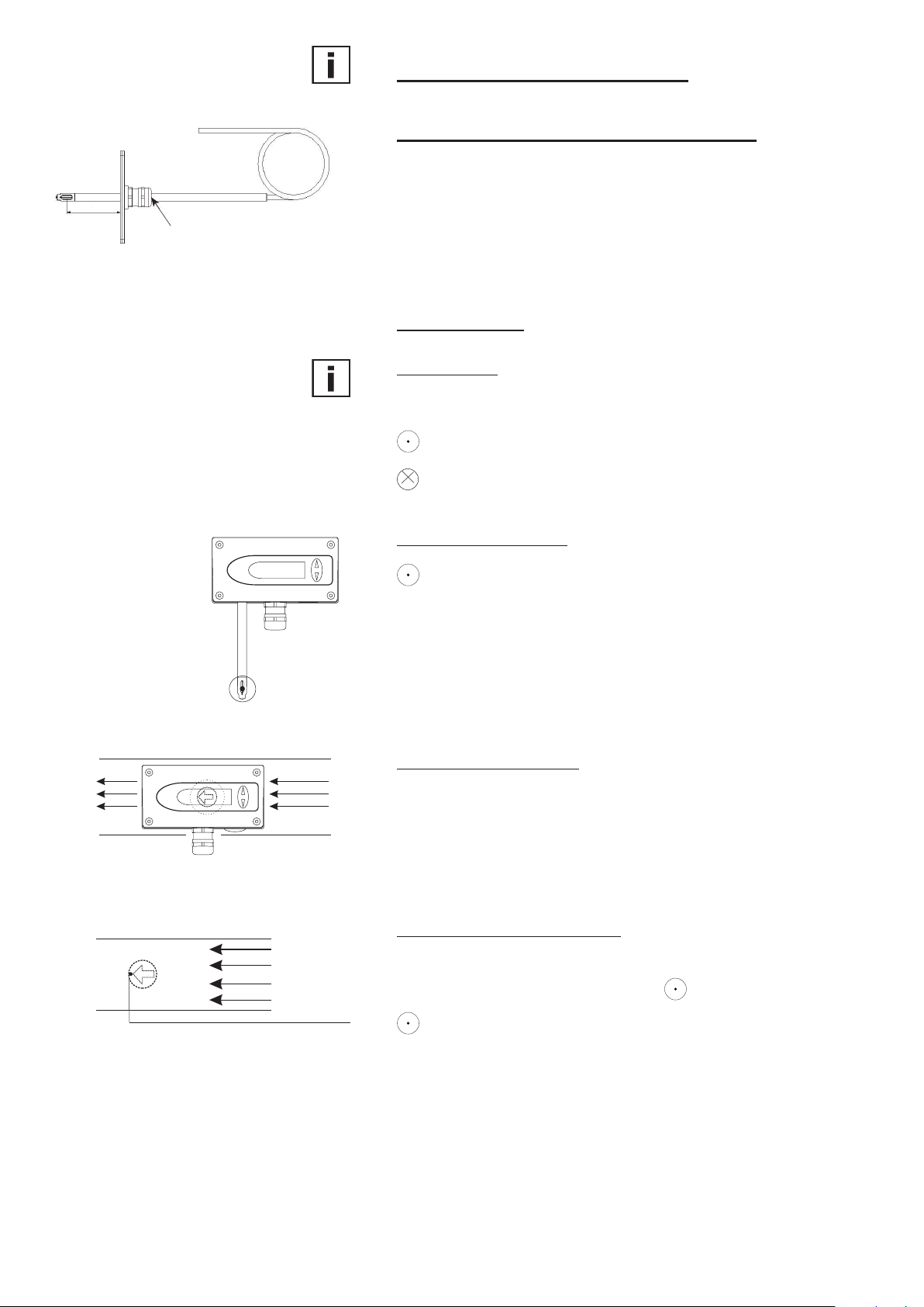
Flow direction
Flow direction:
The arrow on the sensor probe should be pointing exactly in the
direction of flow!
indicates the orientation of the tip of the arrow.
indicates the orientation of the tail of the arrow.
Model A (wall mounting):
indicates the orientation of the tip of the arrow.
Models B (duct mounting):
Models C and E (remote probe):
To be able to read off the orientation of the remote sensor head beyond
the measuring line, a mark has been punched at the end of the
sensing probe. This corresponds with:
flow
corresponds to the tip of the arrow
6
Hardware
Page 8
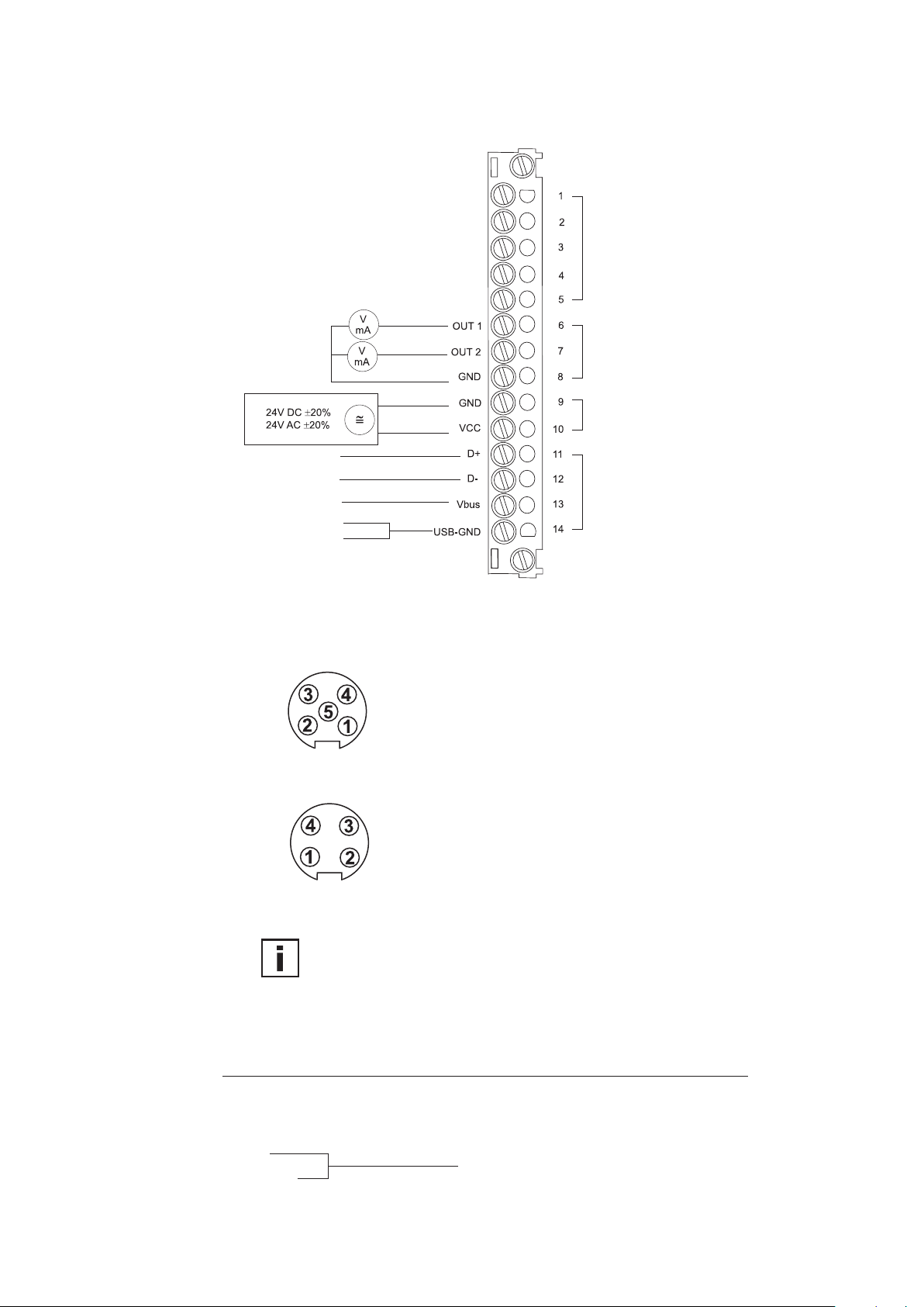
4. ELECTRICAL CONNECTIONS
4.1 Connection diagram
brown
black
red
orange
shield
green
white
red
black
shielding
measuring probe
analogue outputs
supply
USB-interface
Coupling for supply
and analogue outputs
(front view)
Plug for USB interface
(front view)
4.2 Connection diagram with plug connections
(optional)
Description: Connection assignment:
VCC 5
GND 4
GND 3
OUT2 2
Euro-Standard
OUT1 1
Description: Connection assignment:
D+ 3
D- 1
V-bus 2
GND 4
Euro-Standard
Cable connection to the plugs should be as indicated by the numbers above.
4.3 Assignment USB - interface cable
colour of wire: signal: terminal no.:
green D+ 11
white D- 12
red Vbus 13
black
shielding
USB-GND 14
Hardware
7
Page 9

5. OPERATING COMPONENTS
5.1 Circuit board
plug connection
blue
iumper
(detail A)
detail A:
Jumper# Function
I current output signal
S signal
U voltage output signal
1 (arrow) τ
2 τ
3 τ
4 free
-velocity (2s)
90-1
-velocity (4s)
90-2
-velocity (10s)
90-3
5 free
5.2 Jumpers for setting the output signal
If the transmitter output signal is set from current to voltage by use of the configuration
software, additionally 2 jumpers must be set on the circuit board as follows:
EE75-VTx6
(for current output, e.g. 4-20mA)
I S U
EE75-VTx3
(for voltage output, e.g. 0-10V)
I S U
5.3 Jumpers for setting the velocity response time
The EE75 series allows users to set the velocity response time:
a) Setting the velocity response time using jumpers:
Jumper position (Also see Section 5.1 - Circuit board): Response time:
no jumper 1.5sec
jumper at pos. 1 2sec (factory setting)
jumper at pos. 2 4sec (factory setting)
jumper at pos. 3 10sec (factory setting)
b) Setting the velocity response time using configuration software:
The response time (τ90) can also be set to any value between 1.5 and 40 s using the
configuration software, without changing the jumpers on the circuit board.
See Configuration Software, Section 4.4 - Response Time
Hardware
8
Page 10

RH: 63.0%
MAX
RH: 63.0%
MIN
5.4 Display module with buttons (optional)
1. Measurand
2. Unit
3. Measurand selection and
4. Min/Max function
5. Measured value
6. Status line
v: 5.43 m/s
v: 5.43 m/s
1. MEASURAND:
2. UNIT:
SI SI US
v Velocity m/s ft/min
T Temperature °C °F
v Volume m³/min ft³/min
4. MIN / MAX FUNCTION:
The MIN/MAX function can be used to record the lowest and highest values measured
for each measurand since the last reset or the last interruption of the power supply.
Highest measured value: MAX
1. Select the required measurand (UP / DOWN button)
2. To display the maximum value, press the UP button and hold it for approx. 5 s.
3. To return to the normal operating mode, press the UP button again and hold it
for approx. 5 s.
Lowest measured value: MIN
1. Select the required measurand (UP / DOWN button)
2. To display the minimum value, press the DOWN button and hold it for approx. 5 s.
3. To return to the normal operating mode, press the DOWN button again and hold
it for approx. 5 s.
By pressing the UP and DOWN buttons simultaneously in normal operating mode the
stored MIN/MAX values for all measurands can be reset by selecting "CLEAR MIN/MAX
BUFFER"; recording can then be restarted (for details see Section 5.3 - Display module with buttons, point 7 - Menu navigation).
3. MEASURAND SELECTION:
Pressing the ∆ or ∇ button
switches between the various
physical quantities (measurands).
Hardware
5. MEASURED VALUE:
The measured value of the respective measurand is indicated.
6. STATUS LINE:
The status line indicates the transmitter's current operating status:
- no indication: normal operating mode / measurement in progress
- MIN or MAX: see point 4 - MIN/MAX function
- CAL LOW: V or T calibration routine for the low adjustment point selected.
- CAL HIGH: V or T calibration routine for the high adjustment point selected.
7. MENU NAVIGATION:
Pressing the UP and DOWN buttons simultaneously for approx. 5 s during a measurement
(in normal operating mode) a 4-line menu is displayed with the following options:
- CALIBRATION: (Calibration)
- FACTORY SETTINGS: (Factory settings)
- CLEAR MIN/MAX BUFFER: (Clear Min/Max buffer)
- EXIT: (returns to normal operating mode without executing any
of the menu items)
Pressing the UP and DOWN buttons moves the cursor “>” on the left-hand side of the
display up and down to select one of the adjacent menu items.
Pressing the UP and DOWN buttons simultaneously for approx. 5 s confirms the selection
and executes the selected menu item.
9
Page 11

6. VELOCITY/TEMPERATURE CALIBRATION
The EE75 can be calibrated / adjusted using either the buttons on the optional display
module or the USB interface and configuration software provided.
Instructions for calibration:
To achieve comparable results to the E+E factory setting, please note following:
a) The adjustment should be done in a wind tunnel with homogeneous, low turbulent
owprole.
b)Inserttheprobe10cmdeepintotheowchannel.
c)Thexturesshouldbemountedoutsidetheowchannelandshouldnotriseintothe
air stream (see drawing):
OK
not OK
6.1 Selecting the appropriate calibration method
(1-point or 2-point calibration)
The EE75 transmitter series can be calibrated in 2 different ways:
- 1-point v/T calibration:
Quick and easy option for obtaining precise measuring results at a specific working
point. 1-point calibration should only be used for very limited working ranges.
- 2-point v/T calibration:
With 2-point calibration, precise measuring results can be obtained over the entire
v/T measuring range. The more complicated 2-point calibration procedure is preferable
to 1-point calibration, if higher precision or a wider working range is required.
6.1.1 General information on 1-point v/T calibration:
If possible the selected calibration point should be similair to the working point (of the
limited working range) of the transmitter.
Example: Working range v 8 - 12m/s (1600 - 2400ft/min) > calibration point at 10m/s (2000ft/min); working
range T 18 - 22°C (64.4 - 71.6°F) - > calibration point at 20°C (68°F).
- If the selected calibration point is < 50% of the max. measuring range, V/T-CAL LOW
should be selected for calibration / adjustment.
- If the selected calibration point is > 50% of the max. measuring range, V/T-CAL HIGH
should be selected for calibration / adjustment.
Example: v measuring range 0 - 10m/s (0 - 2000ft/min); actual working range 6 - 8m/s (1200 - 1600ft/min);
selected calibration point 7m/s (1400ft/min); perform 1-point calibration, selecting V-CAL HIGH.
Hardware
10
Page 12

6.1.2 General information on 2-point v/T calibration:
With 2-point calibration, v/T calibration / adjustment is performed at 2 different calibration points.
To ensure the smallest possible deviation in measuring results over the entire measuring range,
the two calibration points should be selected as follows:
- The low calibration point should be in the lower third of the measuring range.
Calibration / adjustment must be performed using the V/T-CAL LOW function.
- The high calibration point should be in the upper third of the measuring range.
Calibration / adjustment must be performed using the V/T-CAL HIGH function.
Example: EE75 vT**1 - measuring range = 0 - 2m/s (0 - 400ft/min).
Low calibration point (V-CAL LOW) should be around 0.4 m/s (0...0.7).
High calibration point (V-CAL HIGH) should be around 1.8 m/s (1.4...2).
6.2 Velocity calibration
6.2.1 Calibration procedure using configuration software
See Configuration Software, Section 4.9.3 - v calibration process using a configurator
6.2.2 Calibration procedure using buttons on the display module (optional)
1. Position the sensor head in the middle of the reference system (wind tunnel).
2. Stabilise the probe at the reference velocity (for at least 1 minute). The temperature of
the measuring probe and the reference system must be approximately the same.
3. Press both buttons for approx. 5 s to display the menu window.
4. Use the buttons and cursor so select the menu item "CALIBRATION" and confirm the
selection.
5. Select "V-Cal" and confirm the selection.
6.1 "1-point calibration":
- Select the calibration point as described in Section 6.1.1.
- If calibration point > 50% of measuring range, select "V-CAL HIGH" and
confirm the selection.
- If calibration point < 50% of measuring range, select "V-CAL LOW" and
confirm the selection.
6.2 "2-point calibration":
- Select the low (high) calibration point as described in Section 6.1.2.
- Approach the low (high) calibration point in the reference system, select
"V-CAL LOW" ("V-CAL HIGH”) on the transmitter and confirm the selection.
7. The status line should display either CAL LOW (CAL HIGH).
8. The measuring value can now be adjusted with the reference value in 0.1m/s (20ft/min)
increments by pressing the UP or DOWN button. The updated value is displayed
immediately and present at the analogue output.
9. To save the adjusted measuring value in the instrument, press both buttons
simultaneously for approx. 5 s, then select "YES" in the "SAVE" menu and confirm the
selection. This exits the calibration routine and the transmitter returns to normal
operating mode.
Selecting "NO" in the "SAVE" menu exits the calibration routine without saving the
adjusted measuring value.
10. In the case of 1-point v calibration, the procedure is now complete.
11. For 2-point v calibration, repeat steps 6.2-9 with the (high) calibration point.
Hardware
6.3 Temperature calibration
6.3.1 Calibration procedure using configuration software
See Configuration Software, Section 4.9.4 - T calibration procedure using a configurator
6.3.2 Calibration procedure using buttons on the display module (optional)
1. Insert the sensor head in the temperature reference system.
2. Allow it to stabilise (min. 15 minutes). The greater the difference in temperature
between the measuring probe and the reference system, the longer the required
stabilisation time.
11
Page 13

3. Press both buttons for approx. 5 s to display the menu window.
4. Use the buttons and cursor to select the menu item "CALIBRATION" and confirm the
selection.
5. Select "T-Cal" and confirm the selection.
6.1 "1-point calibration":
Select the calibration point as described in Section 6.1.1.
- If calibration point > 50% of measuring range, select "T-CAL HIGH" and confirm the
selection.
- If calibration point < 50% of measuring range, select "T-CAL LOW" and confirm the
selection.
6.2 "2-point calibration":
Select the low (high) calibration point as described in Section 6.1.2.
- Approach the low (high) calibration point in the reference system, select
"T-CAL LOW" ("T-CAL HIGH") on the transmitter and confirm the selection.
7. The status line should display either CAL LOW (CAL HIGH).
8. The measuring value can now be adjusted with the reference value in 0.1°C (32.18°F)
increments by pressing the UP or DOWN button. The updated value is displayed
immediately and present at the analogue output.
9. To save the adjusted measuring value in the instrument, press both buttons
simultaneously for approx. 5 s, then select "YES" in the "SAVE" menu and confirm the
selection. This exits the calibration routine and the transmitter returns to normal
operating mode.
Selecting "NO" in the "SAVE" menu exits the calibration routine without saving the
adjusted measuring value.
10. In the case of 1-point T calibration, the procedure is now complete.
11. For 2-point T calibration, repeat steps 6.2-9 with the (high) calibration point.
6.4 Resetting to factory calibration
If necessary the transmitter can be reset to the factory settings (factory calibration data),
after a v or T customer calibration has been performed.
6.4.1 Resetting v/T to factory calibration:
1. Press both buttons for approx. 5 s to display the menu window.
2. Select "Factory settings" and confirm the selection.
3. Select "Restore Settings" and confirm the selection.
4. The customer calibration data (v, T) has now been reset to the factory calibration data.
6.4.2 Resetting v to factory calibration:
1. Press both buttons for approx. 5 s to display the menu window.
2. Select "Calibration" and confirm the selection.
3. Select "V-CAL" and confirm the selection.
4. Select "V-FACTORY SETTINGS" and confirm the selection.
5. Select "Restore Settings" and confirm the selection.
6. The customer calibration data (v) has now been reset to the factory calibration data.
6.4.3 Resetting T to factory calibration:
1. Press both buttons for approx. 5 s to display the menu window.
2. Select "Calibration" and confirm the selection.
3. Select "T-CAL" and confirm the selection.
4. Select "T-FACTORY SETTINGS" and confirm the selection.
5. Select "Restore Settings" and confirm the selection.
6. The customer calibration data (T) has now been reset to the factory calibration data.
12
Hardware
Page 14

7. SELF-HELP / MAINTENANCE
- If the measuring values are unrealistic, the first thing to check is the angle of inflow.
- Also check the sensor element for soiling. If dust has collected on the element, blow it off
carefully with oil-free compressed air. If there is anything else on the sensor, clean it
carefully using isopropyl alcohol and allow it to dry. Do not touch the velocity sensor with
your fingers!
- If there is no output and indication, check the power supply.
8. REPLACEMENT PARTS / ACCESSORIES
- Stainless steel mounting plate HA010207
- USB interface cable HA010310
9. TECHNICAL DATA
Measuring value
Air velocity
Working range 0... 2m/s
0... 10m/s
0... 40m/s
Accuracy 1) in air at 25°C (77°F) 2) 0.06... 2m/s (12...400ft/min) ± 0.03m/s / 6ft/min
at 45% RH and 1013hPa 0.15...10m/s
0.2... 40m/s
Uncertainty of factory calibration
1)
± (1% of measuring value, min. 0.015m/s
Temperature dependence electronics typ. -0.0 05 % of measur ing value / °C
Temperature dependence probe ± (0 .1% of measur ing value/°C )
Dependence of angle of inflow: < 3% for α < 20°
of direction of inflow: < 3%
3)
τ
Response time
< 1.5...40s (configurable)
90
Temperature
Working range probe: -40...120°C (-40...248°F)
probe cable: -40...105°C (-40...221°F)
electronic: -40...60°C (-40...140°F)
electronic with display: -30...60°C
Accuracy at 20°C (68°F) ±0.5°C (±0.9°F)
Temperature dependence electronics typ. -0.01°C / °C
Response time
3)
τ
90
10s
Outputs
output signals and display ranges are freely scaleable (see ranges below)
voltage 0-10V (e.g: 0-5V, 1-5V etc.) -1mA < I
current (3-wire) 0-20mA (e.g: 4-20mA etc.) R
v-scaling 0...2 / 10 / 40m/s
T-scaling -40...120°C (-40...248°F)
Vol-scaling 0...10000m³/min (0...353147ft³/min)
General
Supply voltage 24V DC/AC ± 20%
Current consumption max. 100mA; max. 160mA (with display)
Connection screw terminals max. 1.5mm
Electromagnetic compatibility EN61326-1 EN61326-2-3 ICES-003 ClassB
Industrial Environment FCC Part15 ClassB
Pressure range Model E pressure tight up to 10bar
Material housing / protection class: metal (AlSi3Cu) / IP65; Nema 4
measuring probe: stainless steel
measuring head: PBT (polybuthylenterephthalat)
System requirements
for configuration software Windows 2000 or Windows XP
Interface USB 1.1
1) The accuracy statement includes the uncertainty of the factory calibration with an enhancement factor k=2 (2-times standard deviation).
The accuracy was calculated in accordance with EA-4/02 and with regard to GUM (Guide to the Expression of Uncertainty in Measurement).
2) Accuracy refers to measurement in air
3) Response time τ
is measured from the beginning of a step change to the moment of reaching 90% of the step.
90
(0...400ft/min)
(0...2000ft/min)
(0...8000ft/min)
(30...2000ft/min) ± (0.10m/s / 20ft/min + 1 % of measuring value)
(40...8000ft/min) ± (0.20m/s / 40ft/min + 1 % of measuring value)
(3ft/min))
(-22...140°F)
< 1mA
L
< 350 Ohm
(0...400 / 2000 / 8000ft/min)
2
(AWG 16)
L
(145psi)
Hardware
13
Page 15

CONFIGURATION SOFTWARE
LIMITED LIABILITY
E+E Elektronik® shall not be held liable for any damages or consequential damages (for
example, but not restricted to, loss of earnings, interruption of business, loss of
information and data or any other financial losses) resulting from the installation, use or impossibility of use of an E+E Elektronik® software product and any associated support services or
non-performance of support services.
1. GENERAL INFORMATION
The configuration software included in the scope of supply provides a user-friendly
alternative to the use of the buttons on the optional display module for adjusting the transmitter
to suit the relevant application or to calibrate / adjust the velocity and temperature settings.
System requirements: Windows XP or higher, interface USB 1.1 or higher.
NOTE:
Any use beyond these purposes is not permitted.
The permanent connection between EE75 and PC via the USB interface in normal operation
may cause a malfunction and does not meet the CE-criteria.
2. INSTALLATION
NOTE:
Administrator authorisations may be required for problem-free installation of the EE75 configuration software.
1. Insert the CD-ROM supplied in the appropriate drive on your PC.
2. Do NOT yet connect the EE75 to the PC using the USB Port.
3. Run "Setup.exe" to install the EE75 configuration software.
4. The InstallShield Wizard for the EE75 configurator is launched.
5. Follow the instructions to install the software.
6. Clicking the "Finish" button completes configuration software installation.
2.1 Installing the USB-interface
NOTE:
The USB interface software must also be installled to allow your PC and the EE75
velocity transmitter to communicate properly.
1. Connect terminals and USB-interface located in the back module of the
EE75 housing under zero-potential conditions
2. Replace and secure the upper module of the housing
3. Connect EE75 to the supply voltage (VCC)
4. You can now connect the EE75 to your chosen USB Port on your PC
(max. transmission distance 3 m).
5. The driver software will be installed automatically
Configurations Software
14
Page 16

If the EE75 configuration software and the associated USB interface have been set up
correctly, a connection has been assigned to the EE75 USB to UART Bridge Controller on
your PC's Control Panel.
See Start/Settings/Control Panel/System/Hardware/Device Manager
6. The configuration software can now be opened by double-clicking the EE75 icon on
your desktop.
7. Specify the selected USB Port (for details, see Configuration Software, Section 3.1 - File)
8. Pressing the "Read" button will start the communication with the EE75 and downloads
its configuration.
Configurations Software
15
Page 17

3. MENU ITEMS
3.1 File
Load Settings:
Save Settings:
Select COM Port:
Exit:
Opens the saved transmitter configuration settings from an archive file on the PC.
Saves the displayed configuration settings in an archive file on the PC.
Selects the USB interface used on your PC.
If the "Remember next time" box is checked, the selected interface will always be used in
future.The number of the USB Port can be found under:
Start -> Settings -> Control Panel -> System -> Hardware -> Device Manager
Closes the configuration software.
Read:
Write:
3.2 Help
Provides general information on the configuration software.
4. EE75 CONFIGURATOR
4.1 Start
The "Start" tab is used to initiate communication with the connected transmitter.
This function downloads the current transmitter configuration and serial number.
The configuration changes made on the other tabs can be uploaded to the
transmitter using the "Write" command.
Note: Execute the "Read" function before making any new configuration change!
16
Configurations Software
Page 18

4.2 Analog
The "Analog" tab allows free configuration and
scaling of the twoanalogue outputs
Range:
Measurement value:
Upper / Lower Limit:
Physical quantity:
The drop-down input field is used either to select a
standardised output signal (0-5 V, 0-10 V, 0-20 mA,
4-20 mA) or to specify a user-defined current/
voltage output range (e.g. 1-9 V).
Specifies the physical quantities the outputs will
represent.
If the measurement value “volumetric flow rate” is
selected, the cross section has to be defined (see
chapter 4.5 cross section).
Specifies the required display range. The limits must
lie within the maximum span as indicated.
Allows a user to choose whether measuring results are displayed and output in
SI units (m/s; °C; m³/min) or US units (ft/min.; °F; ft³/min.).
4.3 Display
With an optional display, the following can be set on the Display tab:
"Display Mode" drop-down input field:
- Single-line display
- Two-line display (factory setting)
"Backlight on" check box
- Activated = ON
- Not activated = OFF
4.4 Response Time
As described under Hardware, Section 5.2 - Jumpers for setting the velocity response time, three
different response times can be set.
In the factory settings, the following response times are assigned to the 3 jumper positions:
Jumper at position 1: τ90 = 2 s
Jumper at position 2: τ90 = 4 s
Jumper at position 3: τ90 = 10 s
Users can also assign a response time of between 1.5 and 40 s to each jumper position using the
configuration software.
Example:
Jumper at position 1: changes from 2 s (factory setting) to 35 s.
The green pilot lamp next to the jumper position indicates which jumper position is
currently set and consequently active.
Note: If the response time of the jumper currently active is changed anduploaded using the
"Write" function, the transmitter's velocity response is switched without changing the hardware
(jumper position).
Configurations Software
17
Page 19

4.5 Cross Section
The EE75 allows volumetric flow to be displayed in [m³/min] or [ft³/min.] (see Hardware,
Section 5.3 - Display module with buttons - Measurands).
The volume is calculated based on the flow velocity measured and the cross section. Consequently,
the cross sectional area of the duct must be entered in [m²] or [ft²].
To make it easier to calculate the cross sectional area, the "Cross sect." tab provides input
assistance:
Circular:
Rectangular:
Measure and enter the duct diameter in [m] or [ft]
- Press "calculate"
- The cross section is calculated and entered in the "Cross sectional area" field
Measure and enter the duct length and width in [m] or [ft]
- Press "calculate"
- The cross section is calculated and entered in the "Cross sectional area" field
If the duct has a different shape or the cross-sectional area is already known, the value can, of
course, also be entered directly in the "Cross sectional area" field, in [m²] or [ft²].
4.6 Probe Cable
The length of the probe cable (transmitter with remote probe) should not normally be changed.
However, if it is necessary to do so, the new (modified) probe cable length must be entered on
the "Probe Cable" tab. This virtually rules out additional measuring errors due to the modified
cable length.
Example: You order an EE75 VTC***K500 (5m /
with 3m (9.8ft). The new cable length of 2m (6.6ft) should be entered and uploaded using the
"Write" function.
Notes:
- The cable length is measured from the centre of the sensor element in the sensor head to
the point where it enters the housing (PG / screw connection).
- To increase the length of the probe cable, the instrument must be returned to E+E Elektronik.
18
16.4ft cable length) and then cut the cable
Configurations Software
Page 20

Switching point OFF
and Hysteresis:
4.7 Switching Off
The low flow cut-off is intended to prevent the
display or output signal fluctuating if the flow is cut
off.
Small differences in temperature in the duct can
produce small flow fluctuations, which would be recorded by the transmitter without the low flow
cut-off.
(switching point OFF + hysteresis = switching point
ON) can be defined in the input fields of the "Switching
Off" tab.
active
switching point OFF
Note:
The EE75 comes with the low flow cut-off function activated, with a switching point OFF of 0.1m/s (20ft/min)and
hysteresis
switching point ON
a hysteresis of 0.05m/s (10ft/min).
Should you require smaller flow velocities to be
displayed, deactivate the low flow cut-off (switching
point OFF + hysteresis = 0m/s or ft/min.).
4.8 Media Correction
The EE75 measures air velocity [m/s] temperature-independent, but pressure-dependent and
is standardised to 45% relative humidity and air
pressure of 1013mbar at the factory.
If e.g. the media pressure is significantly different, the actual values can be defined in the input
field on the "Mediacorr." tab to obtain the best possible measuring results.
4.9
Calibration
Velocity and temperature calibration is not only possible using the buttons on the integrated display,
the EE75 can also easily be calibrated / adjusted using the configuration software.
Note:
The configuration software automatically distinguishes between the low and high calibration points.
- If the selected calibration point is BELOW the centre of the measuring range, it is automatically
recognised as the "low calibration point" (CAL LOW).
- If the selected calibration point is ABOVE the centre of the measuring range, it is automatically
recognised as the "high calibration point" (CAL HIGH).
Example:
EE75 VT**1: Measuring range = 0-2m/s (0-400ft/min) -> centre of measuring range = 1m/s (200ft/min)
- 0.5m/s (100ft/min) -> calibration point lies below 1m/s (200ft/min) -> CAL LOW
- 1.6m/s (300ft/min) -> calibration point lies above 1m/s (200ft/min) -> CAL HIGH
Configurations Software
19
Page 21

4.9.1 Information on 1-point v/T calibration
If possible the selected calibration point should be similair to the working point
(of the limited working range) of the transmitter.
Example:
Working range v 8 - 12m/s (1600 - 2400ft/min) > calibration point at 10m/s (2000ft/min);
working range T 18 - 22°C (64.4 - 71.6°F) > calibration point at 20°C (68°F).
4.9.2 Information on 2-point v/T calibration
v/T calibration / adjustment is performed at 2 different calibration points.
To ensure the smallest possible deviation in measuring results over the entire
measuring range, the two calibration points should be selected as follows:
- The low calibration point should be in the lower third of the measuring range.
- The high calibration point should be in the upper third of the measuring range.
Example:
EE75 vT**1 - measuring range = 0 - 2 m/s
- Low calibration point (V-CAL LOW) should be around 0.4 m/s (0...0.7).
- High calibration point (V-CAL HIGH) should be around 1.8 m/s (1.4...2).
(0 - 400ft/min)
4.9.3 v calibration procedure using the configuration software
1. Position the sensor head in the middle of the reference system (wind tunnel).
2. Set the required calibration point in the reference system (wind tunnel).
3. Stabilise the probe at the reference velocity (for at least 1 minute).
4. Clicking on the "Velocity calibration" button opens the menu window shown below.
5. Enter the velocity displayed by the reference system in the "Reference value"
input field.
6. Clicking "Save" adjusts the EE75 measuring value with the reference value.
7. In the case of 1-point calibration, the process is now complete.
8. For 2-point calibration, repeat steps 2-7.
4.9.4 T calibration procedure using the configuration software
Click on the "Temperature calibration" button. The 1 or 2-point temperature
calibration procedure is similar to the velocity calibration (see Section 4.9.3 -
v calibration process using a configurator).
4.9.5 Activating factory calibration
Clicking the "Activate factory calibration" button deletes the customer calibration
data set for velocity and temperature and restores the factory settings.
Configurations Software
20
Page 22

4.10 Measuring Values
The configuration software allows the EE75 measuring values to be queried periodically on the
"Measuring Values" index card.
If the "Activate automatic Query" function is activated, all measuring values are downloaded
according to the specified interval and displayed in the desingated fields.
This function is particularly useful for checking transmitters, which do not have the (optional) display
module.
Model:
Serial number:
Software version:
Production date:
Last customer V adjustment:
Last customer T adjustment:
4.11 Information
The "Information" tab contains general information on the transmitter. It also saves the date of
the last customer calibration done with the configuration software.
Type of transmitter.
Reference to the serial number of the connected transmitter.
Version of the firmware used.
Date of production.
Date of last velocity adjustment.
Date of last temperature adjustment.
Configurations Software
21
21
Page 23

22
Configurations Software
Page 24

HEAD OFFICE:
E+E ELEKTRONIK Ges.m.b.H.
Langwiesen 7
A-4209 Engerwitzdorf
Austria
Tel: +43 7235 605 0
Fax: +43 7235 605 8
info@epluse.com
www.epluse.com
TECHNICAL OFFICES:
E+E CHINA / BEIJING
Tel: +86 10 84992361
info@epluse.cn www.epluse.cn
E+E CHINA / SHANGHAI
Tel: +86 21 61176129
info@epluse.cn www.epluse.cn
E+E GERMANY
Tel: +49 6172 13881 0
info@epluse.de www.epluse.de
E+E FRANCE
Tel : +33 4 7472 35 82
info@epluse.fr www.epluse.fr
E+E ITALIEN
Tel: +39 02 2707 86 36
info@epluse.it www.epluse.it
E+E KOREA
Tel: +82 31 732 6050
info@epluse.co.kr www.epluse.co.kr
E+E USA
Tel: +1 508 530 3068
office@epluse.com www.epluse.com
 Loading...