

Page 1
EE75
The EE75 series air velocity transmitters were developed to
obtain accurate measuring results over a wide range of velocities
and temperatures.
A high-quality hot film sensor element based on cutting-edge thin
film technology ensures maximum sensitivity, even at lowest mass
flows. At the same time, the innovative probe design produces reliable measuring results at high flow velocities of up to 40m/s (8000ft/min).
The integrated temperature compensation minimises the temperature
cross-sensitivity of the EE75 series which, combined with the robust
mechanical design, allows it to be used at process temperatures
between -40 to +120 °C (-40 to 248 °F).
High-Precision Air / Gas Velocity Transmitter
for Industrial Applications
In addition to air velocity and temperature values, the transmitter
calculates the volumetric flow rate in m³/min or ft³/min. The cross
section of the duct needs to be determined for this purpose and the
volumetric flow rate can be displayed and directed to one of the
analogue outputs.
The configuration software included in the scope of supply allows to
choose the appropriate output parameter and freely scale the display range and signal level of the two analogue outputs. In addition
user-friendly calibration of the air velocity and temperature and the
adjustment of key parameters (e.g. response time of the velocity
measurement, low flow cut-off points, etc.) are supported as well.
An optional illuminated display with two control buttons integrated in
the cover is available. In addition, this enables changes of the configuration to be made directly on the unit.
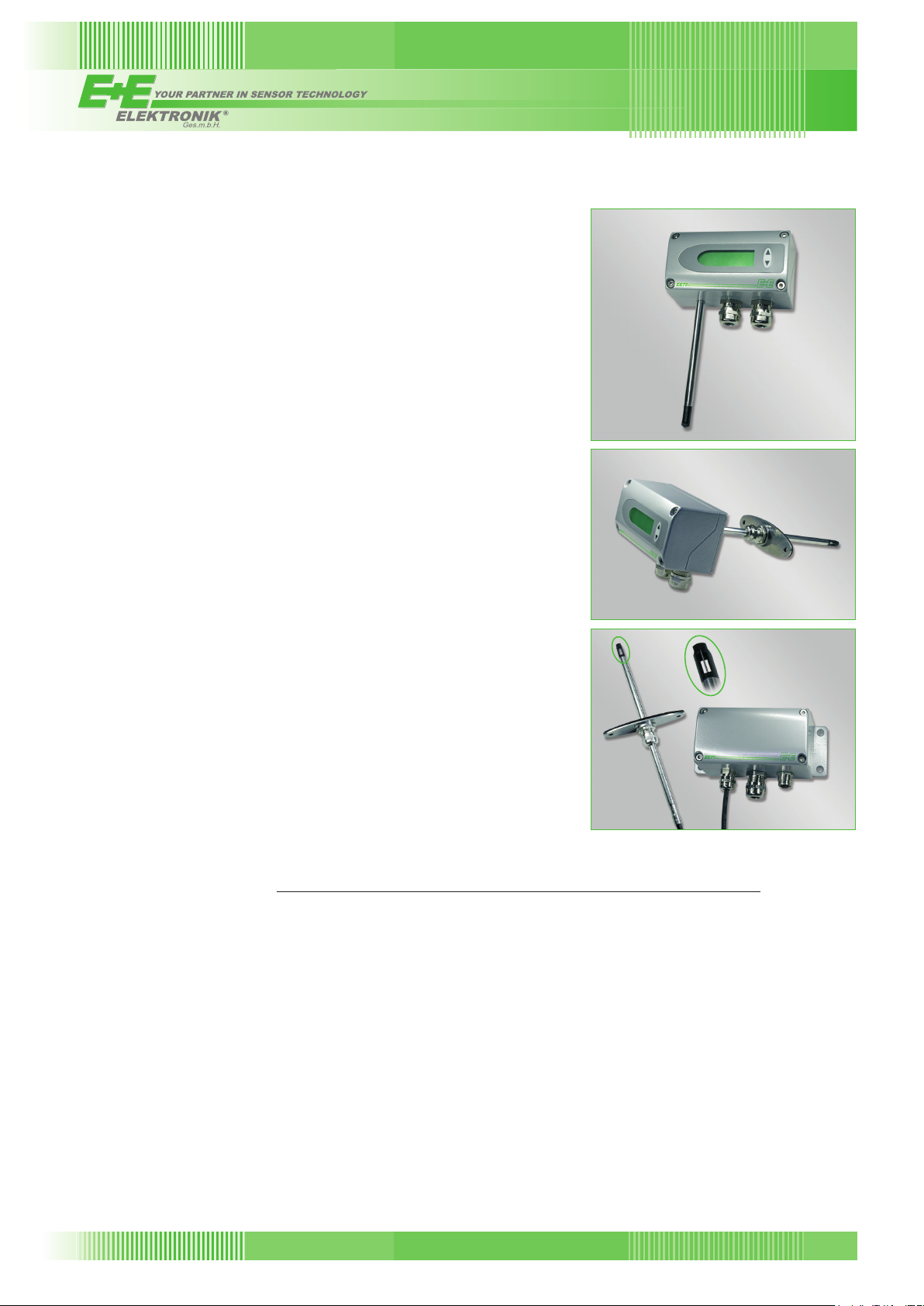
The EE75 series has a robust metal housing to protect against
possible damage in rough industrial environments. There are four different models, providing a comprehensive range of mounting options:
- Model A for wall mounting
- Model B for duct mounting
- Model C with remote probe
- Model E with remote probe, pressure-tight up to 10bar (145psi)
The EE75 series can be used to measure the velocity of other
gasses as well, although a correction has to be applied to the unit at
the factory.
Model A
Model B
Model C
Typical Applications
- monitoring incoming and outgoing air
(energy management) in HVAC applications
- filter monitoring and laminar flow
control in cleanrooms
- exhaust systems, exhaust hoods and
glove boxes in the pharmaceutical,
bio and semiconductor industries
- mass flow measurement during
incineration processes
- monitoring and measurement
of compressed air systems
- air conveying systems
- wind tunnels and climate simulators
156
Features
high accuracy
working range 0...40 m/s
measurement of air velocity and temperature
calculation of volumetric flow rate
low dependence on angle of inflow
probe diameter 8 mm
remote probe up to 10 m (32.8 ft)
easy mounting and maintenance
correction for pressure, humidity and media
pressure tight up to 10 bar
SI and US units selectable
v2.0 / Modification rights reserved
(0...8000 ft/min) and
-40...120 °C (-40...248 °F)
low flow cut-off
(145 psi)
(0.3”)
EE75
EE75
Page 2
Technical Data
Measuring value
Air velocity
Working range 0... 2 m/s
0... 10 m/s (0...2000 ft/min)
0... 40 m/s (0...8000 ft/min)
Accuracy1) in air at 25 °C (77 °F)2) 0.06... 2 m/s (12...400 ft/min) ± 0.03 m/s / 6ft/min
at 45 % RH and 1013 hPa 0.15...10 m/s
0.2... 40 m/s (40...8000 ft/min) ± (0.20 m/s / 40 ft/min + 1 % of measuring value)
Uncertainty of factory calibration
1)
± (1 % of measuring value, min. 0.015 m/s (3 ft/min))
Temperature dependence electronics typ. -0.005 % of measuring value / °C
Temperature dependence probe ± (0.1 % of measuring value/°C)
Dependence of angle of inflow: < 3 % for α < 20°
of direction of inflow: < 3 %
Response time
3)
τ
< 1.5...40 s (configurable)
90
Temperature
Working range probe: -40...120 °C (-40...248 °F)
probe cable: -40...105 °C (-40...221 °F)
electronic: -40...60 °C (-40...140 °F)
electronic with display: -30...60 °C (-22...140 °F)
Accuracy at 20 °C (68 °F) ±0.5 °C (±0.9 °F)
Temperature dependence electronics typ. -0.01 °C / °C
Response time
3)
τ
90
10 s
Outputs
output signals and display ranges are freely scaleable (see ranges below)
voltage 0-10 V (e.g: 0-5 V, 1-5 V etc.) -1 mA < I
current (3-wire) 0-20 mA (e.g: 4-20 mA etc.) RL< 350 Ohm
v-scaling 0...2 / 10 / 40 m/s (0...400 / 2000 / 8000 ft/min)
T-scaling -40...120 °C (-40...248 °F)
Vol-scaling 0...10000 m³/min (0...353147 ft³/min)
General
Supply voltage 24 V DC/AC ± 20 %
Current consumption max. 100 mA; max. 160 mA (with display)
Working range humidity 0...99 % RH - no condensation
Connection screw terminals max. 1.5 mm
Electromagnetic compatibility EN61326-1 EN61326-2-3 ICES-003 ClassB
Industrial Environment FCC Part15 ClassB
Pressure range Model E pressure tight up to 10 bar (145 psi)
Material housing / protection class: metal (AlSi3Cu) / IP65; Nema 4
measuring probe: stainless steel
measuring head: PBT (polybuthylenterephthalat)
System requirements
for configuration software Windows 2000 or higher
Interface USB 1.1
1) The accuracy statement includes the uncertainty of the factory calibration with an enhancement factor k=2 (2-times standard deviation).
The accuracy was calculated in accordance with EA-4/02 and with regard to GUM (Guide to the Expression of Uncertainty in Measurement).
2) Accuracy refers to measurement in air
3) Response time τ
is measured from the beginning of a step change to the moment of reaching 90% of the step.
90
(0...400 ft/min)
(30...2000 ft/min) ± (0.10 m/s / 20 ft/min + 1 % of measuring value)
< 1 mA
L
2
(AWG 16)
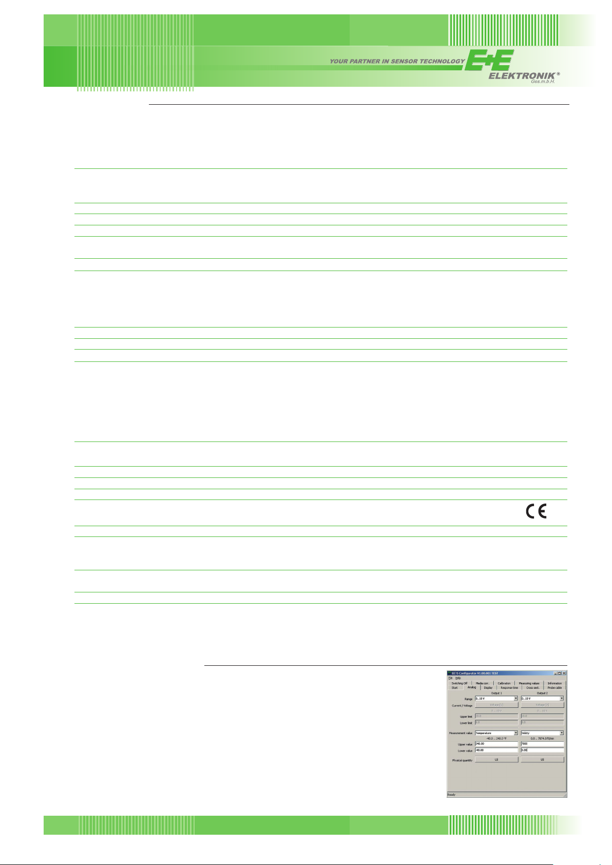
Configuration Software
An easy setup of the EE75 can be made via standard USB interface and the
software included in the scope of supply.
The user can easily set the response time, correct for the gas (air)
pressure, perform an one or two point adjustment and define the duct cross
section for the volumetric flow rate.
EE75
v2.0 / Modification rights reserved
157
Page 3

Angular Dependence
The innovative design of the probe head
minimises the effect of the angle of
inflow on the measuring result. The
deviation of the measuring value remains
< 3 % up to an angle of inflow (α) of ± 20°
between the direction of inflow and the
sensor element's longitudinal axis.
velocity
sensor
measuring error [%]
α
angle of inflow α [°]
Low flow cut-off
Small temperature differences in shut-off pipes and ducts can cause minimal flows. Even these would
be detected and measured by the EE75. The resulting fluctuations in the output signal can be suppressed
by the low flow cut-off. Cut-off point and switching hysteresis can be specified using the configuration
software.
Calculation of volumetric flow
The EE75 measures air velocity in m/s or ft/min. The configuration software can be used to enter the crosssection. This enables the transmitter to calculate the volumetric flow rate in m³/min or ft³/min. The data can
be displayed and directed to one of the analogue outputs.
Connection versions
plug option C13 plug option C14
Lumberg
RKC 5/7
Lumberg
RSC 5/7
M16x1.5
M16x1.5
plug option C12standard
Lumberg
RKC 5/7
Lumberg
RSC 5/7
Connection Diagram
158
power supply +
analogue output
power supply +
analogue output
measuring probe
analogue outputs
supply
USB-interface
USB
power supply +
analogue output
v2.0 / Modification rights reserved
USB
EE75
Page 4

Dimensions in mm
145 (5.7”)
115 (4.5”)
code “probe length”
60 (2.4”)
56 (2.2”)
∅8 (0.3”)
12 (0.5”)
EE75-VTB
Duct mounting
code “cable length”
code “probe length”
∅8 (0.3”)
12 (0.5”)
EE75-VTC
Remote probe
code “probe length”
12 (0.5”)
(0.3”)
∅8
EE75-VTA
Wall mounting
Mounting flange (included in the scope of supply)
2 (0.08")
sealing
80 (3.1")
EE75
v2.0 / Modification rights reserved
code “cable length”
code “probe length”
∅8 (0.3”)
12 (0.5”)
1/2” ISO or 1/2” NPT
EE75-VTE
Remote, pressure tight probe
up to 10 bar (145psi)
159
Page 5

Ordering Guide
EE75-VTB
EE75-VTC
EE75-VTE
EE75-VTA
Hardware Configuration
Output 0...10 V 3 3 3 3
Working range 0...2 m/s 1 1 1 1
Probe length 200 mm 5 5 5 5
Cable length 2 m K200 K200
Display without display
Pressure tight 1/2” ISO thread HA03
feedthrough 1/2” NPT thread HA07
Plug cable glands
Software Configuration
Physical output 1 Select according to
parameters Temperature T [°C] (B)
outputs Velocity v [m/s] (N) output 2 Select according to
Measured value metric /SI
units non metric / US E01 E01 E01 E01
Scaling of v-output 0...0.5 (V01) 0...30 (V10) 0...2000 (V18)
in m/s or ft/min
Scaling of T-ouput -40...60 (T02) -30...120 (T09) 0...80 (T21)
in °C or °F
Measurement Air
1) Please declare the duct cross-section [m²] with your order.
4...20 mA 6 6 6 6
0...10 m/s 2 2 2 2
0...40 m/s 3 3 3 3
400 mm 6 6 6 6
600 mm 7 7 7 7
5 m K500 K500
10 m K1000 K1000
with display D06 D06 D06 D06
1 plug for power supply and outputs C12 C12 C12 C12
2 plugs for power supply / outputs and USB C13 C13 C13 C13
1 plug for USB C14 C14 C14 C14
1)
Volume
0...1 (V02) 0...35 (V11) 0...3000 (V19)
0...1.5 (V03) 0...40 (V12) 0...4000 (V20)
0...2 (V04) 0...100 (V13) 0...5000 (V21)
0...5 (V05) 0...200 (V14) 0...6000 (V22)
0...10 (V06) 0...300 (V15) 0...7000 (V23)
0...15 (V07) 0...400 (V16) 0...7800 (V24)
0...20 (V08) 0...1000 (V17) 0...8000 (V25)
0...25 (V09)
-10...50 (T03) -20...120 (T10) -40...80 (T22)
0...50 (T04) -10...70 (T11) -20...80 (T24)
0...100 (T05) -40...120 (T12) -20...60 (T25)
0...60 (T07) 20...120 (T15) -30...50 (T45)
-30...70 (T08) -30...60 (T20) -20...50 (T48)
Nitrogen N B B B B
Carbon dioxide CO
v [m³/min] (O)
2
Ordering Guide (B,N,O)
Ordering Guide (B,N,O)
Select according to
Ordering Guide (Vxx)
Select according to
Ordering Guide (Txx)
Other T Scaling refer to
data sheet „T-Scalings“
C C C C
Order Example
EE75-VTB325C12/BN-V05-T07
Model: duct mounting
Output: 0...10 V
Working range: 0...10 m/s
Probe length: 200 mm (7.9”)
Display: without
Plug: 1 plug for power supply and outputs
Output 1: T
Output 2: v
Measured value units: metric / SI
v-Scaling: 0...5 m/s
T-Scaling: 0...60 °C
Measurement media: air
160
(0...2000 ft/min)
v2.0 / Modification rights reserved
EE75
 Loading...