

Page 1
USER‘S GUIDE
EE671 - Miniature Air Flow Transmitter
GENERAL
The EE671 air velocity transmitter operates on the hot-film anemometer principle and features an innovative, very robust E+E
sensing element manufactured in thin-film technology combined with innovative transfer-molding.
The mounting flange allows for correct positioning and easy adjustment of the immersion depth.
EE671 is dedicated for accurate and reliable measurement in building automation and ventilation applications. For special
applications do not hesitate to contact the manufacturer or their local distributor.
CAUTION
• Accurate measurement results are conditioned by the correct positioning of the probe in the air stream. Best accuracy is achieved
in laminar flow
• Observe the minimum inlet and outlet path length, see page 4.
• Avoid mechanical stress on the probe and mainly onto the sensing head.
• Observe the humidity working range 5 … 95 % RH, non-condensing.
• Avoid installation in corrosive environment, as this may lead to sensor destruction.
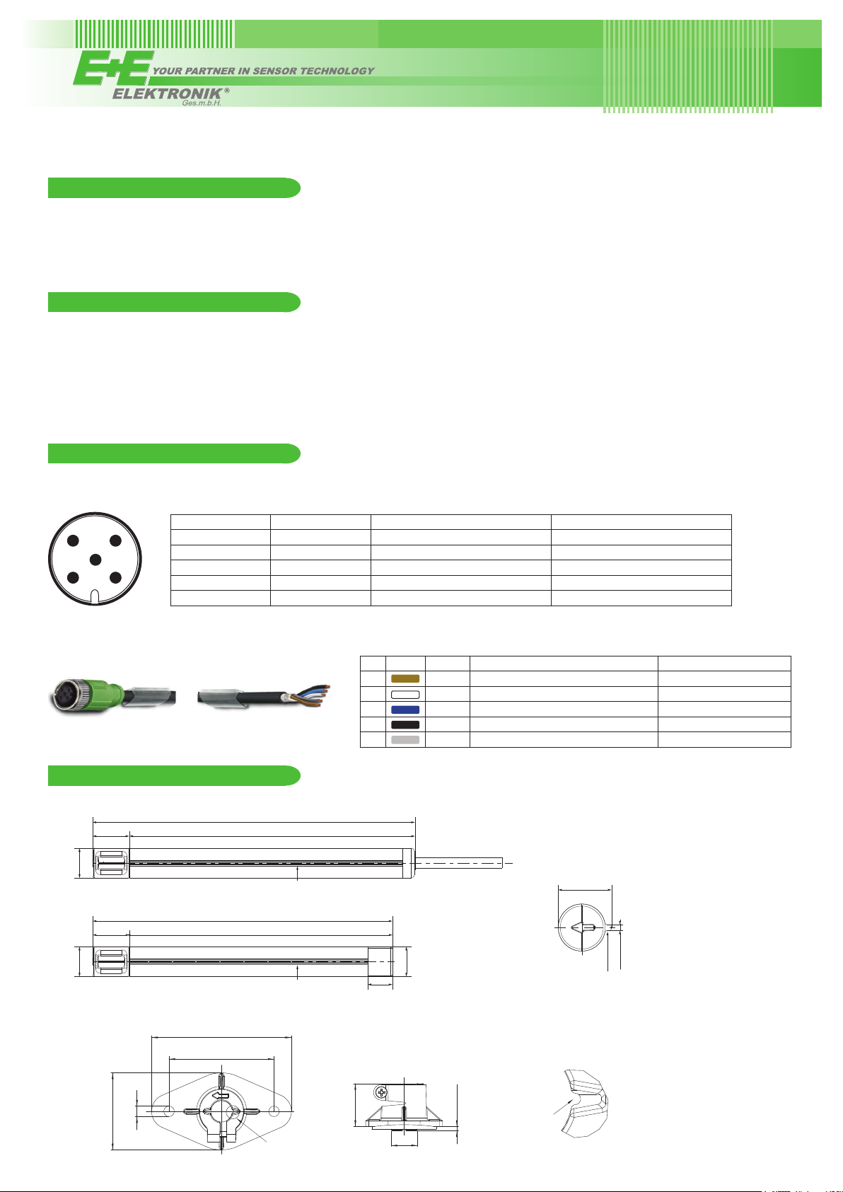
WIRING
EE671 is ESD-sensitive device. It is neither short-circuit-proof, nor not surge-proof. The digital communication lines may not be
connected to the supply lines.
4
5
1 2
3
Plug version Cable version Analogue output Modbus RTU output
1 grey SDA (digital setup interface E2) V+ = Supply voltage
2 brown GND RS485-B (=D-)
3 green AV = Analogue output RS485-A (=D+)
4 yellow SCL (digital setup interface E2) GND
5 white V+ = Supply voltage n.c.
view on
sensor plug
Accessory HA0108xx - connecting cable
DIMENSIONS mm (inch)
Cable version:
15 (0.6“)
ø12
(0.47“)
Plug version:
15 (0.6“)
130 (5.12“)
115 (4.53“)
Führungssteg / alignment strip
121 (4.76“)
106 (4.17“)
Analogue output Modbus RTU output
1 brown SDA (digital setup interface E2) V+ = Supply voltage
2 white GND RS485-B (=D-)
3 blue AV = Analogue output RS485-A (=D+)
4 black SCL (digital setup interface E2) GND
5 gray V+ = Supply voltage n.c.
Front view sensor head:
13.4 (0.53“)
Flange:
ø12
(0.47“)
44 (1.7“)
6 (0.2“)
Führungssteg / alignment strip
80 (3.14“)
60 (2.4“)
Detail A
10 (0.4“)
24.5 (0.9”)
M12x1
15.8 (0.62”)
2.5 (0.1”)
Recess for alignment strip
Detail A:
Führungssteg /
alignment strip
1.5 (0,06“)
Page 2

TECHNICAL DATA
Flow measurement
Measurement range
0... 10 m/s (0...2000 ft/min)
0... 15 m/s (0...3000 ft/min)
0... 20 m/s (0...4000 ft/min)
Output signal
analogue1) 0 - 1 V (max. 1 mA)
0 - 5 V (max. 1 mA)
0 - 10 V
RS485 Modbus RTU
Accuracy3) 0.5...5 m/s (100...1000 ft/min): ±(0.2 m/s / 40 ft/min + 3 % of measured value)
at 20 °C (68 °F) / 45 % rh and 1013 hPa (14.7 psi) 1... 10 m/s (200...2000 ft/min): ±(0.3 m/s / 60 ft/min + 4 % of measured value)
1... 15 m/s (200...3000 ft/min): ±(0.35 m/s / 70 ft/min + 5 % of measured value)
1... 20 m/s (200...4000 ft/min): ±(0.4 m/s / 80 ft/min + 6 % of measured value)
Response time
1)
0... 5 m/s (0...1000 ft/min)
2)
τ
typ. 4 s
90
(max. 1 mA)
General
Supply voltage (Class III) 10...29 V DC SELV
Current demand max. 50 mA at 20 m/s
(4000 ft/min)
Temperature range operation: -20...60 °C (-4...140 °F)
storage: -30...60 °C (-22...140 °F)
Operating range humidity 5...95 % RH (non-condensing)
Connection
Cable version 0.5 m (1.6 ft) / 2 m (6.6 ft) cable, PVC, temperature-flexible,
5x0.25 mm² (AWG 23) with ferrules
Plug version M12 connector system, 5-pin
Electromagnetic compatibility
4)
EN61326-1 ICES-003 ClassB
EN61326-2-3 FCC Part 15
Material / protection class polycarbonate / IP50 (probe head); IP54 (housing)
1) See ordering information
2) Only at supply voltage V+ ≥ 15 V
3) The accuracy statement includes the uncertainty of the factory calibration with an enhancement factor k=2 (2-fold standard deviation). The tolerance was calculated in
accordance with EA-4/02 following the GUM (Guide to the Expression of Uncertainty in Measurement).
4) The EE671 is not short-circuit-proof and not surge-proof (ESD-sensitive device).
SCOPE OF SUPPLY
• EE671 transmitter according to ordering guide
• Protection cap
• Mounting flange
• User manual
MODBUS RTU
The EE671 air flow transmitter can be operated in a Modbus RTU network with max. 32 devices. For Modbus protocol settings see
Application Note Modbus AN0103 (www.epluse.com/EE671).
The factory setting for the Slave-ID is 238 as an integer 16Bit value. This ID can be customised in the register 0x00 (value margin
1 - 247 permitted).
MODBUS MAP:
Register
[DEC]
Read registers (function code 0x03 / 0x04)
30001 0x00 Serial number ASCII
30009 0x08 Software version Binary
30010 0x09 Transmitter name ASCII
30026 0x19 Temperature °C 32-bit float
30028 0x1B Temperature °F 32-bit float
30030 0x1D Temperature K 32-bit float
30032 0x1F Air velocity m/s 32-bit float
30034 0x21 Air velocity ft/min 32-bit float
30046 0x2D Temperature °C x 100 16-bit integer
30047 0x2E Temperature °F x 100 16-bit integer
30048 0x2F Temperature K x 100 16-bit integer
30049 0x30 Air velocity m/s x 100 16-bit integer
30050 0x31 Air velocity ft/min x 10 16-bit integer
Write registers (function code 0x06)
60001 0x00 Network address
60002 0x01 Communication parameter
Protocol
address [HEX]
Measured value Unit Type
Page 3

MOUNTING
Whenever possible use the mounting flange for installing the EE671. The flange allows for correct positioning in the flow and for easy
adjustment of the immersion depth.
The arrows engraved on the sensing head of EE671 and on the mounting flange indicate the direction of the air stream during factory
adjustment.
Observe the direction of the arrow when installing the mounting flange.
Once the mounting flange is correctly aligned to the air flow direction, the alignment strip along the probe assures that the EE671 is
also correctly aligned.
CORRECT
INCORRECT
air flow
MOUNTING INTO A DUCT
drilling in the wall of the duct:
>16 (0.63")
air flow
60 (2.4")
The mounting flange allows also for precise setting of the EE671 immersion depth. The entire sensing head must be in the air flow to
be measured.
CORRECT INCORRECT
Immersion depth = 30 % - 50 %
of the duct diameter
air flow
duct diameter
When installing the EE671 probe without the mounting flange, make sure that the arrow on the sensing head matches exactly the flow
direction.
CORRECT INCORRECT
air flow
Page 4

MOUNTING GUIDELINES FOR AIR VELOCITY MEASURING DEVICES
For accurate measurement results it is of paramount importance to place the sensing probe at a location with low turbulence, such as
after filters, rectifiers, heaters or coolers. Turbulence appears after obstructions like fans, bends, junctions or section changes in the
duct (diffusers / confusers), so the probe shall be placed far enough from these. The minimum length of the settling zone (straight duct
section without obstructions whatsoever) between the probe and the source of turbulence depends on the diameter of the duct. An
“equivalent diameter” Dgl can be defined for a rectangular duct with dimensions a · b:
The following pictures supply guidelines for correct installation of air velocity transducers with respect to location and to minimum
recommended settling zones.
Install the sensor in the middle of the duct.
The preferred position of the sensor is after a filter.
<6D
<6D
+
>6D
Place the sensor in front of the diffusers at a position with high air
velocity.
>3D
Place the sensor at a position with laminar (non turbulent) flow.
Turbulence appears after fans as well as after bends, junctions, air heater, air cooler, filters, flaps or diameter changes in the duct.
>6D
>3D
>6D
MAINTENANCE OF THE E+E AIR VELOCITY TRANSMITTERS
Due to the absence of moving parts, the E+E air velocity transmitters are not subject to wear. The construction (shape, dimensions
and materials) of the hot film air velocity sensor is per se highly insensitive to dust and dirt. No maintenance is required under normal
environmental conditions. For operation in polluted environment it is advisable to periodically clean the sensing head by washing it in
isopropyl alcohol, preferably in an ultrasound cleaner. Alternatively shake it gently few minutes in a pot with isopropyl alcohol and let it
dry free. Do not touch or rub the sensor and do not use any mechanical tools for cleaning.
Page 5

USA
FCC notice:
This equipment has been tested and found to comply with the limits for a Class B digital device, pursuant to part 15 of the FCC Rules. These limits are
designed to provide reasonable protection against harmful interference in a residential installation. This equipment generates, uses and can radiate radio
frequency energy and, if not installed and used in accordance with the installation manual, may cause harmful interference to radio communications.
However, there is no guarantee that interference will not occur in a particular installation. If this equipment does cause harmful interference to radio or
television reception, which can be determined by turning the equipment off and on, the user is encouraged to try to correct the interference by one or
more of the following measures:
- Reorient or relocate the receiving antenna.
- Increase the separation between the equipment and receiver.
- Connect the equipment into an outlet on a circuit different from that to which thereceiver is connected.
- Consult the dealer or an experienced radio/TV technician for help.
CANADIAN
ICES-003 Issue 5:
CAN ICES-3 B / NMB-3 B
INFORMATION
E+E Elektronik Ges.m.b.H.
Langwiesen 7 • A-4209 Engerwitzdorf
Tel: +43 7235 605-0 • Fax: +43 7235 605-8
info@epluse.com • www.epluse.com
LG Linz Fn 165761 t • UID-Nr. ATU44043101
Place of Jurisdiction: A-4020 Linz • DVR0962759
+43 7235 605 0 / info@epluse.com
BA_EE671_e // v2.5 // Technische Änderungen vorbehalten
 Loading...