

Page 1
EE650
The EE650 air velocity transmitter is dedicated for accurate and reliable
measurement in building automation and ventilation applications.
The device employs an innovative air velocity sensing element, which
operates on the thermal anemometer principle and is manufactured by
E+E in state-of-the-art thin lm technology. Due to its innovative design,
the sensing element is very robust and highly insensitive to pollution,
which leads to outstanding long-term performance.
For the EE650 with analogue output, the measuring range 0-10/15/20 m/s
(0-2000/3000/4000 ft/min), the output signal 4-20 mA or 0-10 V as well as the
response time 1 or 4 seconds are selectable by jumpers.
The bus address, the termination resistor and the response time of the
Modbus RTU and BACnet MS/TP versions can also be easily set on the
electronics board.
The enclosure design and the mounting ange included in the scope of
supply allow for fast and easy installation.
With an optional adapter cable and the free EE-PCS product conguration
software, the user can adjust the EE650, set the output scale and select
the interface parameters.
Air Velocity Transmitter for
HVAC Applications
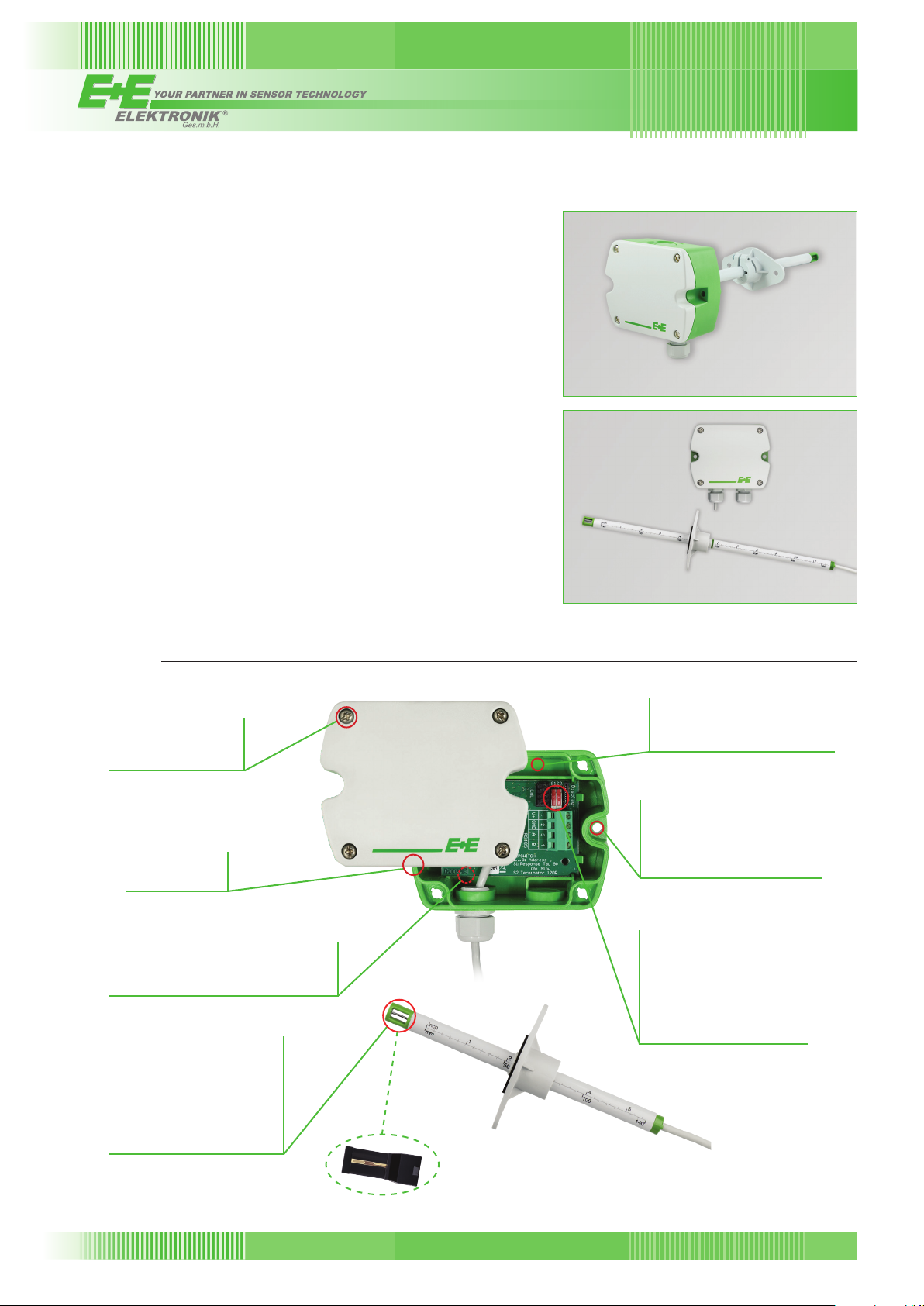
EE650 - Duct mounting
EE650 - Remote sensor probe
Features
Bayonet Screws
» Open/closed with a
¼ rotation
Enclosure
» IP65 / Nema 4
Electronics on the underside of the PCB
» Protection against mechanical
damage during installation
E+E Air velocity sensor VTQ
» Exceptional mechanical
stability thanks to transfer-
moulding technology
» High insensitivity to pollution
» Long-term stable
» Measurement down to 0.2 m/s
(40 ft/min)
Appropriate for US mounting
requirements
» Knock-out for ½” conduit tting
External mounting holes
» Fast and easy installation
with closed cover
» Electronics protected against
construction site pollution
Adjustment
Conguration
» Measuring range
» Output signal
» Response time
» Bus address
» Termination resistor
176
v2.0 / Modification rights reserved
EE650
EE650
Page 2
Technical data
V+
GND
AV
1
2
3
+
-
~
~
V/mA
M16x1,5
Measuring range
Working range 1) 0...10 m/s (0...2000 ft/min)
0...15 m/s (0...3000 ft/min)
0...20 m/s (0...4000 ft/min) (factory setting)
Accuracy at 20 °C 2) (68 °F), 0.2...10 m/s (40...2000 ft/min) ± (0.2 m/s (40 ft/min) + 3 % of m. v.)
45 % RH, 1013 hPa 0.2...15 m/s
0.2...20 m/s
Response time
Output
Analogue 1) 0 - 10 V -1 mA < IL < 1 mA
0...10 m/s / 0...15 m/s / 0...20 m/s 4 - 20 mA
Digital interface RS485 with max. 32 devices on one bus
Protocol Modbus RTU or BACnet MS/TP
General
Power supply (Class III) 24 V AC/DC ± 20 %
Current consumption
Electrical connection screw terminals max. 1.5 mm
Cable gland M16x1.5
Electromagnetic compatibility EN61326-1 EN61326-2-3
Industrial Environment
Enclosure material Polycarbonate, UL94V-0 approved
Protection class Enclosure IP65 / NEMA 4, remote probe IP20
Temperature range working temperature probe -25 ... 50 °C
working temperature electronic -10 ... 50 °C
storage temperature -30 ... 60 °C
Working range humidity 5...95 % RH (non-condensing)
1) Selectable by jumper, only for analogue output
2) The accuracy statement includes the uncertainty of the factory calibration with an enhancement factor k=2 (2-times standard deviation).
The accuracy was calculated in accordance with EA-4/02 and with regard to GUM (Guide to the Expression of Uncertainty in Measurement).
(40...3000 ft/min) ± (0.2 m/s (40 ft/min) + 3 % of m. v.)
1)
τ
typ. 4 sec. (factory setting) or typ. 1 sec. at constant temperature
90
(40...4000 ft/min) ± (0.2 m/s (40 ft/min) + 3 % of m. v.)
(factory setting) R
< 500 Ω (linear, 3-wires)
L
AC supply DC supply
Analogue ouput max. 170 mA max. 70 mA
RS485 max. 120 mA max. 50 mA
2
(AWG 16)
(-13...122 °F)
(14...122 °F)
(-22...140 °F)
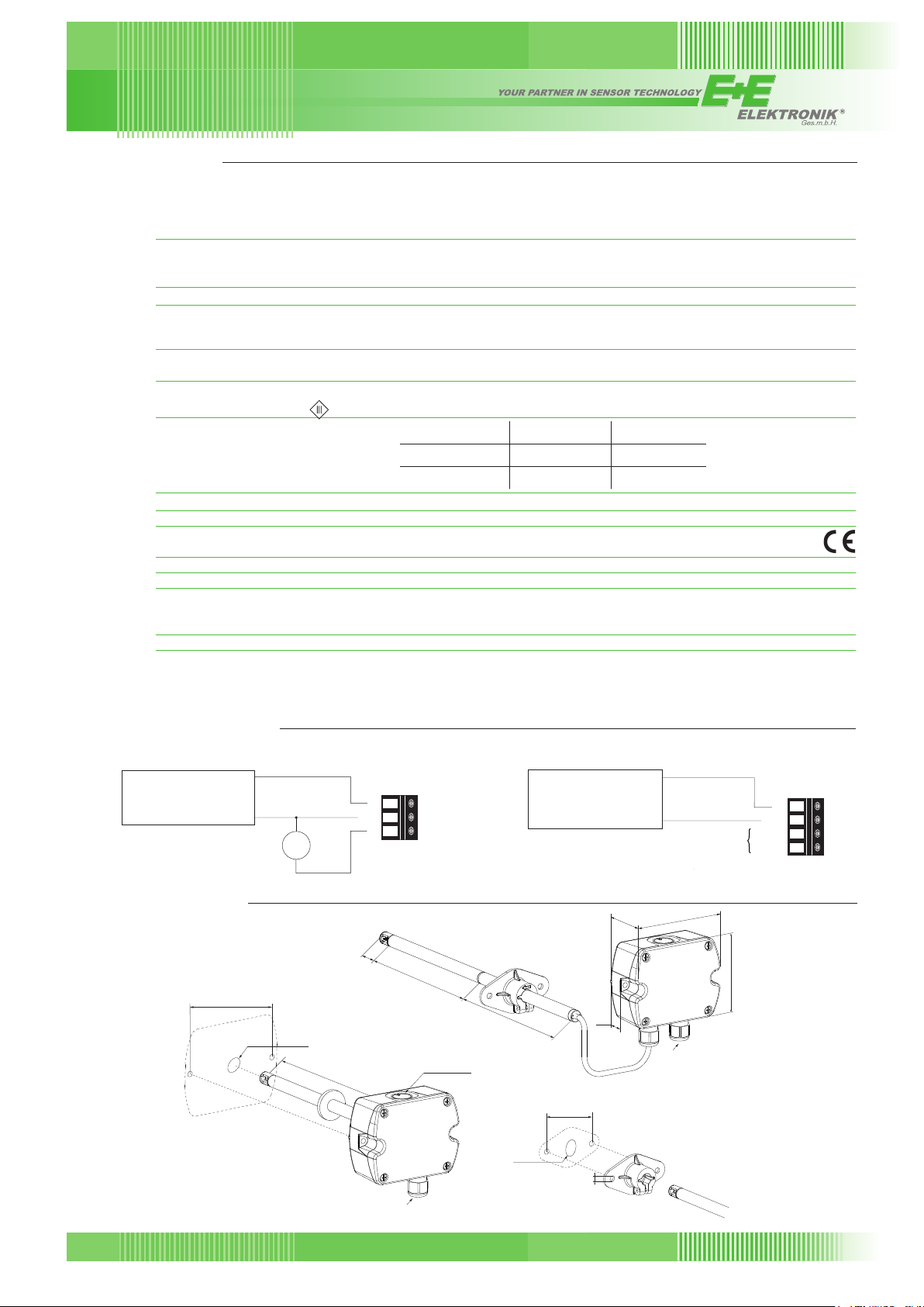
Connection Diagram
Analogue output
power supply
24 V AC/DC ±20 %
+
~
~
Dimensions (mm)
90
Duct mount
V/mA
Ø > 13
~110 or 210
GND
15
Digital interface
power supply
V+
AV
1
2
3
24 V AC/DC ±20 %
+
~
-
~
RS485
46
101
V+
GND
A (=D+)
B (=D-)
1
2
3
4
Remote sensor probe
155
FOR CONDUIT
INSTALLATION
155
19
Cable gland
M16x1,5
60
80,6
Mounting flange
Ø > 16
6
EE650
v2.0 / Modification rights reserved
Cable gland
177
Page 3

Ordering Guide
Type
Output
Probe length
Cable length
Hardware Configuration
Protocol
Baud rate
Setup RS485
1) Factory setting: Even Parity, Stopbits 1 Modbus Map see User Guide at www.epluse.com/ee650
2) Factory setting: No Parity, Stopbits 1 Product Implementation Conformance Statement (PICS) available at www.epluse.com/ee650
3) Only for BACnet MS/TP
Duct mounting T2
Remote sensor probe T3
4-20 mA (selectable by jumper to 0-10 V) A6 A6
RS485 J3 J3
100 mm L100
200 mm L200
300 mm (2 x 150 mm) L300
not applicable no code
1 m K1
2 m K2
5 m K5
10 m K10
Modbus RTU
BACnet MS/TP
9600 BD5
19200 BD6
38400 BD7
57600
76800
1)
P1
2)
3)
3)
EE650-
P3
BD8
BD9
Order Example
EE650-T2A6L200
Type: duct mounting
Output: 4-20 mA
Probe length: 200 mm
EE650-T3A6L300K2
Type: remote sensor probe
Output: 4-20 mA
Probe length: 300 mm
Cable length: 2 m
Scope of Supply
- EE650 Transmitter according to ordering guide
- Cable gland (two pieces at output RS485 for daisy chain wiring)
- Mounting flange
- Mounting materials
- Protection cap
- Quick guide
- Two self-adhesive labels for configuration changes (see user guide at www.epluse.com/relabeling)
- Test report according to DIN EN10204 - 2.2
Accessories
USB configuration adapter HA011066
Product configuration software EE-PCS (free download: www.epluse.com/EE650)
Power supply adapter V03 (see data sheet Accessories)
EE650-T2J3L200P1BD5
Type: duct mounting
Output: RS485
Probe length: 200 mm
Protocol: Modbus RTU
Baud rate: 9600
178
v2.0 / Modification rights reserved
EE650
 Loading...