

Page 1

User Manual
EE610
Low Differential Pressure Sensor
BA_EE610_e // v1.1 // technical data are subject to change
Page 2

E+E Elektronik Ges.m.b.H. accept warranty and liability claims neither upon this publication nor in case of improper
treatment of the described products.
The document may contain technical inaccuracies and typographical errors. The content will be revised and
updated on aregular basis. The described products can be improved and changed at any time without prior notice.
© Copyright E+E Elektronik Ges.m.b.H.
All rights reserved.
EMC note USA (FCC):
This equipment has been tested and found to comply with the limits for a Class A digital device, pursuant to part 15
of the FCC Rules. These limits are designed to provide reasonable protection against harmful interference when
the equipment is operated in a commercial environment. This equipment generates, uses, and can radiate radio
frequency energy and, if not installed and used in accordance with the instruction manual, may cause harmful
interference to radio communications. Operation of this equipment in a residential area is likely to cause harmful
interference in which case the user will be required to correct the interference at his own expense.
EMC note Canada (ICES-003):
CAN ICES-3 (A) / NMB-3 (A)
Page 3

CONTENT
1 General ................................................................................................................................................. 4
1.1 Explanation of symbols .................................................................................................................................4
1.1.1 General safety instructions ..................................................................................................................................4
1.1.2 Mounting, start-up and operation .........................................................................................................................4
1.2 Environmental aspects ..................................................................................................................................5
2 Scope of Supply .................................................................................................................................5
3 Product Description ............................................................................................................................ 6
4 Setup ...................................................................................................................................................7
4.1 Analogue version ...........................................................................................................................................7
4.1.1 Select the measurement range with S1 and S2 ...................................................................................................7
4.1.2 Select the response time with S3 and S4 ............................................................................................................7
4.1.3 Select the display unit with S5 and S6 ................................................................................................................7
4.1.4 Select the backlight for the display with S7 ..........................................................................................................7
4.1.5 Select the output signal with S8 ...........................................................................................................................8
4.1.6 Outputs.................................................................................................................................................................8
4.2 Digital version ................................................................................................................................................8
4.2.1 EE-PCS Product Configuration Software .............................................................................................................9
4.2.2 RS485 Digital Interface settings ...........................................................................................................................9
4.2.3 BACnet Protocol Settings ....................................................................................................................................9
4.2.4 Modbus Protocol Settings ....................................................................................................................................9
4.2.5 Modbus Register Map ........................................................................................................................................10
4.2.6 Reading example ...............................................................................................................................................10
5 Installation ......................................................................................................................................... 11
5.1 Pressure connection ....................................................................................................................................11
6 Maintenance and service .................................................................................................................. 12
6.1 Cleaning ......................................................................................................................................................12
6.2 Repairs ........................................................................................................................................................12
6.3 Readjustment of EE610 ..............................................................................................................................13
6.3.1 Zero Point Adjustment ........................................................................................................................................ 13
6.3.2 Span Point Adjustment ....................................................................................................................................... 13
6.3.3 Return to Factory Adjustment ............................................................................................................................ 14
7 User Interface ....................................................................................................................................14
7.1 LED indication ............................................................................................................................................14
7.2 Display .........................................................................................................................................................14
7.2.1 Analogue version ...............................................................................................................................................14
7.2.2 Digital version..................................................................................................................................................... 14
7.2.3 Out of range ....................................................................................................................................................... 14
8 Technical Data ..................................................................................................................................15
Page 4
1 General
This user manual serves for ensuring proper handling and optimal functioning of the device.
The user manual shall be read before commissioning the equipment and it shall be provided to all staff
involved in transport, installation, operation, maintenance and repair.
The user manual may not be used for the purposes of competition without the written consent of E+E
Elektronik® and may not be forwarded to third parties. Copies may be made for internal purposes. All
information, technical data and diagrams included in these instructions are based on the information
available at the time of writing.
1.1 Explanation of symbols
This symbol indicates safety information.
It is essential that all safety information is strictly observed. Failure to comply with this information can
lead to personal injuries or damage to property. E+E Elektronik® assumes no liability if this happens.
This symbol indicates instructions.
The instructions shall be observed in order to reach optimal performance of the device.
1.1.1 General safety instructions
• Avoid any unnecessary mechanical stress and inappropriate use.
• Installation, electrical connection, maintenance and commissioning shall be performed by
qualified personnel only.
• Use the EE610 only as intended and observe all technical specs.
• Do not blow into the pressure connections.
• Connecting to EE610 a pressure beyond the measurement range according to the product specification may permanently damage the device.
• Do not use EE610 in explosive atmosphere or for measurement of aggressive gases.
• Do not apply the nominal voltage to the output terminals.
1.1.2 Mounting, start-up and operation
The EE610 differential pressure sensor has been produced under state of the art manufacturing conditions, has been thoroughly tested and has left the factory fulfilling all safety criteria. The manufacturer
has taken all precautions to ensure safe operation of the device. The user must ensure that the device
is set up and installed in a manner that does not have a negative effect on its safe use.
The user is responsible for observing all applicable safety guidelines, local and international, with respect to safe installation and operation on the device. This operating manual contains information and
warnings that must be observed by the user in order to ensure safe operation.
• Mounting, start-up, operation and maintenance of the device may be performed by qualified staff only.
Such staff must be authorised by the plant operator to carry out the mentioned activities.
• The qualified staff must have read and understood this operating manual and must follow the instructions contained within.
• All process and electrical connections shall be thoroughly checked by authorised staff before putting
the device into operation.
• Do not install or start-up a device supposed to be faulty. Make sure that such devices are not
accidentally used by marking them clearly as faulty.
• A faulty device may only be investigated and possibly repaired by qualified, trained and authorised
staff. If the fault cannot be fixed, the device shall be removed from the process.
• Service operations other than described in this operating manual may only be performed by the
manufacturer.
4
User Manual EE610 Low Differential Pressure Sensor
Page 5

Disclaimer
The manufacturer or his authorised agent can only be held liable in case of willful or gross negligence.
In any case, the scope of liability is limited to the corresponding amount of the order issued to the
manufacturer. The manufacturer assumes no liability for damages incurred due to failure to comply with
the applicable regulations, operating instructions or the operating conditions. Consequential damages
are excluded from the liability.
1.2 Environmental aspects
Products from E+E Elektronik® are developed and manufactured observing of all relevant requirements
with respect to environment protection. Please observe local regulations for the device disposal.
For disposal, the individual components of the device must be separated according to local recycling
regulations. The electronics shall be disposed of correctly as electronics waste.
2 Scope of Supply
• EE610 differential pressure sensor according to ordering guide
• Quick user guide
• Test report according to DIN EN 10204 – 2.2
• Pressure connection kit, straight, including 2 m hose
• Mounting materials
• For digital version (J3 ordering code): one additional M16 x 1.5 cable gland for “Daisy chain” wiring
User Manual EE610 Low Differential Pressure Sensor
5
Page 6

3 Product Description
0.2“
V+
GND
AV
1
2
3
+
-
~
~
+
V/mA
±0.3
90
mm
±0.11
“
3.54
46 mm
1.81“
FOR CONDUIT
INSTALLATION
5 mm
0.2“
3.17“
80.6 mm
Pressure ttings Ø 5mm
+ : High pressure
- : Low pressure
5 mm
CABLE GLAND M16x1.5
Fig. 1 Dimensions
Analogue version (A7) Digital version (J3)
2
5
2
4
4
3
1
6
7
5
6
3
1
89
1. Pressure connection nipples
2. DIP switches: Configuration (Ranges, response
time, ...)
3. Terminals: spring loaded
4. Push buttons for zero point and span point adjust
ment
5. Status LED
6. Cable gland for wiring
1. Pressure connection nipples
2. DIP switches: RS485 addressing
3. Terminals: screw
4. Push buttons for zero point and span point adjust
-
ment
5. Status LED
6. Slide switch termination resistor
7. Service interface connector
8. Cable gland for wiring
9. Additional cable gland for daisy chain wiring
Fig. 2 Design and components
Analogue version (A7) Digital version (J3)
15...35 V DC
24 V AC ±20 %
power supply
24 V AC ±20 %
15...35 V DC
-
~
~
RS485
V+
GND
A (=D+)
B (=D-)
1
2
3
4
Fig. 3 Connection diagram
6
User Manual EE610 Low Differential Pressure Sensor
Page 7

4 Setup
0 0 0 0 0 0 0 0
1 1 0 0 0 0 0 0
4.1 Analogue version
Each EE610 leaves the E+E factory with the default setup (all switches on „0“):
• Measurement range: ±100 Pa
• Response time: 50 ms
• Display unit: Pa
• Backlight display: on
• Output signals: 0-10 V and 4-20 mA
EE610 is fully configurable. Before commissioning, set the individual configuration of EE610 according
to the application requirements using the DIP switches S1 to S8 as described below. The function of the
DIP switches is indicated also on the interior of the EE610 front cover.
1
0
Fig. 4 DIP switches examples
4.1.1 Select the measurement range with S1 and S2
EE610-HV51A7:
S1 S2 Pa mbar inch WC mm H
0 0 ±100 ±1 ±0.4 ±10.2
1 0 ±50 ±0.5 ±0.2 ±5.1
0 1 ±25 ±0.25 ±0.1 ±2.55
1 1 0-100 0-1 0-0.4 0-10.2
Tab. 1 DIP switch settings - Measurement range
4.1.2 Select the response time with S3 and S4
S3 S4 Response time
0 0 50 ms
1 0 500 ms
0 1 2 s
1 1 4 s
Tab. 2 DIP switch settings - Response time
1
0
O
2
4.1.3 Select the display unit with S5 and S6
Tab. 3 DIP switch settings - Display unit
4.1.4 Select the backlight for the display with S7
Tab. 4 DIP switch settings - Blacklight
User Manual EE610 Low Differential Pressure Sensor
S5 S6 Display unit
0 0 Pa
1 0 mbar
0 1 inch WC
1 1 mm H
S7 Backlight
0 on
1 off
O
2
7
Page 8

4.1.5 Select the output signal with S8
EE610 provides simultaneously a voltage and a current output signal at the spring terminals.
S8 Output signals
0 0-10 V and 4-20 mA
1 0-5 V and 0-20 mA
Tab. 5 DIP switch settings - Output signals
4.1.6 Outputs
The measured data is available at the spring terminals as 0-10 V and 4-20 mA or as 0-5 V
and 0-20 mA signals (see „4.1.5 Select the output signal with S8“).
Additionally, the analogue outputs indicate measurement out of range as follows.
If negative or positive differential pressure exceeds the span value of the selected measuring range by
5 % the analogue outputs indicate measurement out of range as follows.
Output signal
0-10 V -0.5 V
0-5 V -0.25 V
4-20 mA 3.2 mA
0-20 mA -1 mA
Tab. 6 Indication of Δp < scale value low, - 5 % of span
Output signal
0-10 V 10.5 V
0-5 V 5.25 V
4-20 mA 20.8 mA
0-20 mA 21 mA
Tab. 7 Indication of Δp > scale value high, + 5 % of span
4.2 Digital version
The EE610 is ready to use and does not require any configuration by the user. The factory setup of
EE610 corresponds to the type number ordered. For ordering guide please see data sheet at
www.epluse.com/ee610. If needed, the user can change the factory setup by using the USB configuration adapter (code HA011066) and the EE-PCS, Product Configuration Software.
One can change the display visualisation (see chapter „7.2.2 Digital version“), the digital communication
parameters (see chapter „4.2.2 RS485 Digital Interface settings“) and the response time.
Δp < scale value low,
- 5 % of span
Δp > scale value high,
+ 5 % of span
Note: The EE610 may not be connected to any additional power supply when using the USB configuration adapter HA011066.
Service interface connector
PC
HA011066
Fig. 5 Configuration adapter
8
User Manual EE610 Low Differential Pressure Sensor
Page 9

4.2.1 EE-PCS Product Configuration Software
0 0 0 0 0 0 0 0
1 1 0 0 0 0 0 0
1
0
1
0
1 1 0 0 0 0 0 0
1
0
1. Download the EE-PCS Product Configuration Software from www.epluse.com/configurator and
install it on the PC.
2. Connect the E+E device to the PC using the appropriate configuration cable.
3. Start the EE-PCS software.
4. Follow the instructions on the EE-PCS opening page for scanning the ports and identifying the
connected device.
5. Click on the desired setup or adjustment mode from the main EE-PCS menu on the left and follow
the online instructions of the EE-PCS.
4.2.2 RS485 Digital Interface settings
Hardware Bus Termination
The bus termination can be realised enabling the slide switch on board (120 Ohm resistor). Factory
setting disabled (see „Fig. 2 Design and components“, Digital version J3).
Address setting via Software
All DIP switches at position 0 → address has to be set via Software (via EE-
PCS Product Configuration Software or via protocol BACnet / Modbus).
Default address 44.
Example: Slave address is set via configuration software.
Address setting via Dip-Switch
Setting the DIP switches to any other address than 0, overrules the default
address (44) or the address set via Software.
Example: Slave address set to 3 (0000 0011 binary).
4.2.3 BACnet Protocol Settings
Baud rate As per type number ordered 9600, 19200, 38400, 57600, 76800, 115200
Data bits 8 8
Parity None None
Stop bits 1 1
Slave address 44 0…127
Tab. 8 BACnet Protocol settings
The recommended settings for multiple devices in a BACnet MS/TP network are 38400, 8, None, 1.
The EE610 PICS (Product Implementation Conformance Statement) is available on the website at
www.epluse.com/ee610.
ID address, baud rate can be set via:
1. EE-PCS, Product Configuration Software and the USB configuration adapter cable code
HA011066. BACnet protocol, see the PICS.
4.2.4 Modbus Protocol Settings
Baud rate As per type number ordered 9600, 19200, 38400, 57600, 76800, 115200
Data bits 8 8
Parity Even None, odd, even
Stop bits 1 1 or 2
Slave address 44 1…247
Tab. 9 Modbus Digital Settings
Factory settings Selectable values
Factory settings Selectable values
User Manual EE610 Low Differential Pressure Sensor
The recommended settings for multiple devices in a Modbus RTU network are 9600, 8, Even, 1.
9
Page 10

ID address, baud rate, parity and stop bits can be set via:
1. EE-PCS, Product Configuration Software and the appropriate configuration cable.
2. Modbus protocol in the register 60001 (0x00) and 60002 (0x01). See Application Note Modbus
AN0103 (available on www.epluse.com/EE610)
The measured values are saved as a 32 bit float value and as 16 Bit signed integer, see the Modbus
Register map below.
The serial number as ASCII-code is located at read register address 30001-30008 (16 bit per address).
The firmware version is located at register address 30009 (bit 15...8 = major release; bit 7...0 = minor
release).
The sensor name is located at register address 30010.
4.2.5 Modbus Register Map
FLOAT 32 bit
1)
Measured value Unit Register number
[DEC] Protocol Address 2) [HEX]
Read register: function code 0x03 / 0x04
Differential pressure mm WC 1211 0x4BA
Differential pressure mbar 1213 0x4BC
Differential pressure Pa 1215 0x4BE
Differential pressure kPa 1217 0x4C0
Differential pressure inch WC 1219 0x4C2
INTEGER 16 bit
Measured value Unit Scale
3)
Register number1) [DEC] Protocol Address 2) [HEX]
Read register: function code 0x03 / 0x04
Differential pressure mm WC 10 4106 0x1009
Differential pressure mbar 100 4107 0x100A
Differential pressure Pa 1 4108 0x100B
Differential pressure kPa 1000 4109 0x100C
Differential pressure inch WC 100 4110 0x100D
INTEGER 16 bit INFO (read register)
Parameter
name
Register
number
1)
[Dec]
Register
address2) [Hex]
Parameter
name
Register
number1) [Dec]
Register
address2) [Hex]
Read and write register: function code 0x03 / 0x06 Read register: function code 0x03 / 0x04
4)
Slave-ID
address
Modbus
protocol settings
1)
Register number starts from 1
2)
Register address starts from 0
3)
100 is scale 1:100 (2550 is equivalent to 25.50)
4)
If the ID is set via DIP-switch the response will be NAK
5)
For Modbus protocol settings please see Application Note Modbus
AN0103 (available on www.epluse.com/EE600)
modbus
5)
0001 0x00
0002 0x01 Firmware version 0009 0x08
Serial number
(as ASCII)
0001 0x00
Sensor Name 0010 0x09
Status / Error
information
0602 0x259
4.2.6 Reading example
Example of MODBUS RTU command for reading the differential pressure (float value) Δp = -32,260543
Pa from the register 0x4BE:
Device EE610; slave ID 44 [2C in Hex]
Reference document, chapter 6.3: www.modbus.org/docs/Modbus_Application_Protocol_V1_1b.pdf
Request [Hex]: 2C 04 04 BE 00 02 16 A2
Modbus ID
address
Request
[Hex]:
10
Function
code
Starting
address Hi
Starting
address Lo
No. of
register Hi
No. of
register Lo
CRC
2C 04 04 BE 00 02 16 A2
User Manual EE610 Low Differential Pressure Sensor
Page 11

Response [Hex]: 2C 04 04 0A CC C2 01 55 C1
Response
[Hex]:
Modbus ID
address
2C 04 04 0A CC C2 01 55 C1
Function
code
Byte
count
Register 1
value Hi
Register 1
value Lo
Register 2
value Hi
Register 2
value Lo
CRC
For decoding of float values (stored according standard IEEE754), please refer to AN0103, chapter 7
(available on www.epluse.com/EE610).
Example of decoding
Response [Hex] Value in decimal
Byte 1
(Register 2 - Hi)
C2 01 0A CC -32,260543
5 Installation
• Mount the EE610 onto a vertical, smooth surface.
• Important: The pressure connection nipples must point downwards.
• Avoid installation close to heaters and sources of strong electromagnetic interference.
• Insert the cable for supply voltage and output signal through the cable gland and connect it to the
spring terminals according to the wiring diagram („Fig. 3 Connection diagram“).
• Important: Make sure that the connecting cable or wires do not impact with the push buttons in order
to prevent unintentional trigger of the span or zero point adjustment.
• Close tightly the cable gland. This is essential for the compliance with the IP65 / NEMA4 protection
class of the EE610 enclosure.
Byte 2
(Register 2 – Lo)
Byte 3
(Register 1 - Hi)
Byte 4
(Register 1 - Lo)
Fig. 6 Mounting orientation
5.1 Pressure connection
Fig. 7 Pressure connection
User Manual EE610 Low Differential Pressure Sensor
11
Page 12

Ø16
Ø7
Ø 7.3
Ø 6.5
60∞
2x Ø2.2
Fig. 8 Dimension of pressure connection nipples
80 18.5
• Install first the pressure connection nipples (included in the scope of supply) onto the duct.
Use a Ø 7.5 mm drill.
• Connect the pressure hose (included in the scope of supply) first to the EE610 and then to the nipples
at the duct. Route the pressure hose for avoiding sharp bends which might lead to the hose
obstruction („Fig. 9 Pressure hose route“).
Fig. 9 Pressure hose route
Important: Make sure to connect the higher pressure at the “+” pressure connector and the lower
pressure at the “-“ pressure connector. Inverted connection leads to “out of range” information on the
optional display and at the analogue outputs, see „4.1.6 Outputs“ and „7.2.3 Out of range“.
6 Maintenance and service
EE610 does not require any special maintenance, nevertheless it is recommended to perform a zero
point adjustment every 12 month. If needed, the enclosure may be cleaned and the device may be
re-adjusted as described below.
6.1 Cleaning
Use a damp soft cloth to remove deposits of dust or dirt from the exterior of the device and from the
display. Do not attempt to clean the interior of the device. Do not use any solvents, alcohol or abrasive
cleaning agents.
6.2 Repairs
Repairs may be carried out by the manufacturer only. The attempt of unauthorised repair excludes any
warranty claims.
12
User Manual EE610 Low Differential Pressure Sensor
Page 13

6.3 Readjustment of EE610
A periodical readjustment of EE610 might be required by the regulations of certain industries or by the
need of best long-term measurement accuracy. The zero point and the span point can be adjusted with
push buttons on the EE610 electronics board.
For adjustment the device must be powered and the enclosure cover removed. Consequently, the
adjustment may be performed by authorised staff only, observing the handling of electrical sensitive
devices (ESD).
6.3.1 Zero Point Adjustment
The zero point adjustment is used to correct an eventual zero point deviation.
a. Remove the tubes from both pressure connections of the EE610. By this the pressure equal on
both connections.
b. Press “zero point” button 1-2 sec. (see „3 Product Description“).
c. The successful zero point adjustment is confirmed by the green LED turning on for 2 seconds.
d. The red LED turning on for 2 seconds indicates that the zero point adjustment did not succeed. In
this case repeat b.
e. The zero point adjustment (b.) may not succeed because of a deviation higher than 5 % of the
original full scale of the device. This is 5 Pa for the 0 – 100 Pa range. In such a case, the zero point
adjustment can be forced by pressing and holding the zero point button for min. 10 sec.
f. The successful zero point adjustment is confirmed by the green LED turning on for 2 seconds.
6.3.2 Span Point Adjustment
The span point adjustment is used to correct an eventual deviation of the span value.
Important:
Make sure to perform a zero point adjustment as above before any span point adjustment.
a. Connect the differential pressure reference device/calibrator to the EE610 and set it according to
the EE610 span value to be adjusted.
b. Note: The span value has to be set according to the selected positive measurement range.
Example:
Analogue version: (see „4.1.1 Select the measurement range with S1 and S2“, Tab. 1)
EE610-HV51A7, S1 = 0, S2 = 1, span value = +25 Pa
Digital version: EE610-HV51J3, span value = +100 Pa
Observe the operation manual of the reference device.
c. Press the span point adjustment button (see „3 Product Description“).
d. The successful span point adjustment is confirmed by the green LED turning on for 2 seconds.
e. The red LED turning on for 2 seconds indicate that the span point adjustment did not succeed. In
this case repeat b.
f. The span point adjustment (b.) may not succeed because of a deviation higher than 5 % of the
original full scale of the device.
This is 5 Pa for the 0 – 100 Pa range. In such a case, the set point adjustment can be forced by
pressing and holding the span point button for 10 sec.
g. The successful span point adjustment is confirmed by the green LED turning on for 2 seconds.
User Manual EE610 Low Differential Pressure Sensor
13
Page 14
6.3.3 Return to Factory Adjustment
Pa
0,1Pa = 0,0004 inch WC 1:250
0,1Pa = 0,001 mbar 1:100
0,1Pa = 0,0101 mm H
2
O 1:10
a. Press and hold simultaneously both “zero” and “span” buttons for 5 sec.
b. The successful return to factory adjustment is confirmed by the green LED turning on for 2 seconds.
c. The red LED turning on for 2 seconds indicates that the return to factory adjustment
did not succeed. In this case repeat b.
Important:
Return to factory adjustment affects both zero and span.
7 User Interface
7.1 LED indication
Green LED
flashing (1 s interval) = EE610 operates normally, the
one flash (2 s) = confirms adjustment or return
off = no power supply or
7.2 Display
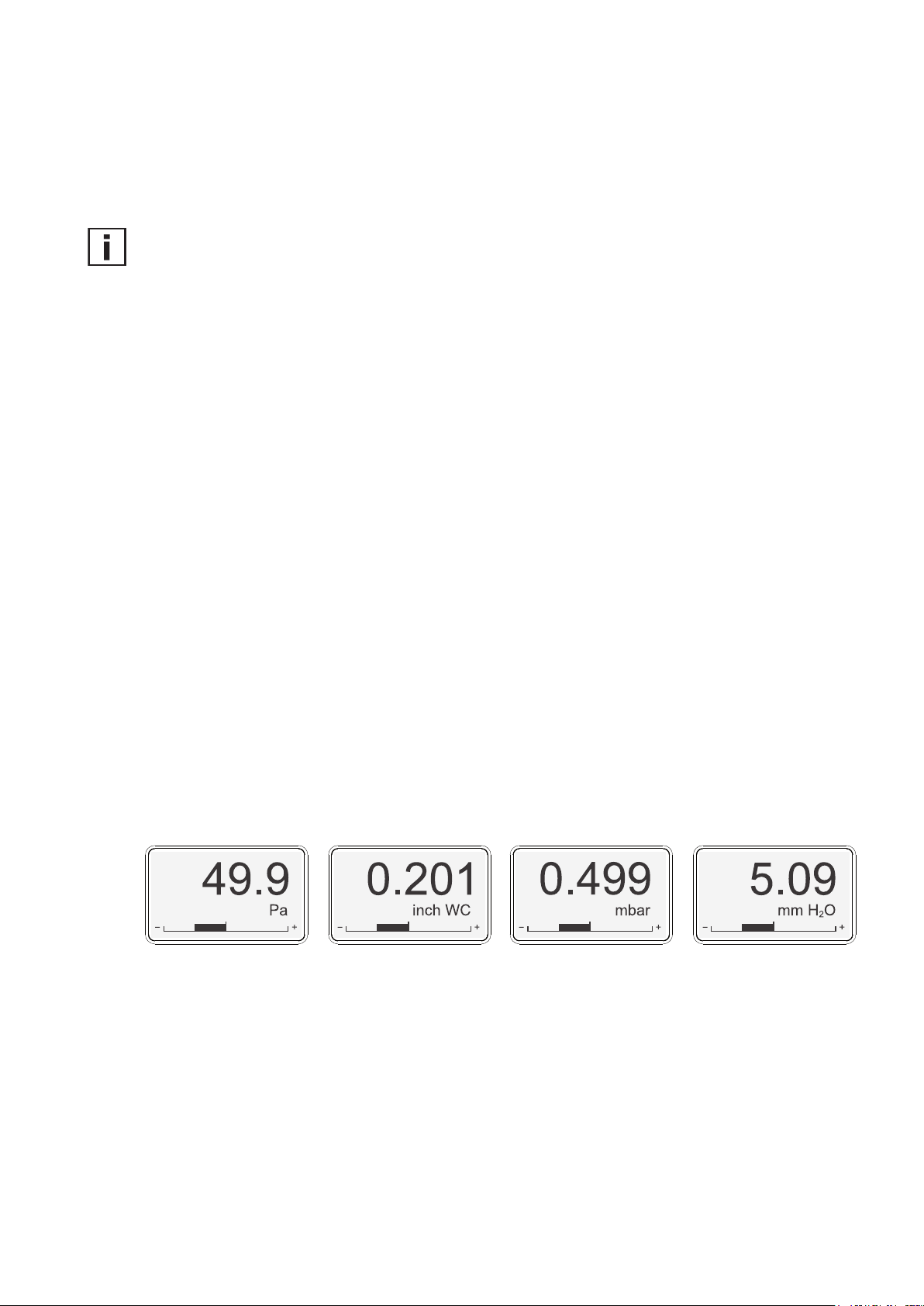
7.2.1 Analogue version
The display shows the measured differential pressure and the selected unit (see „4.1.3 Select the display unit with S5 and S6“).
Additionally, the bar graph indicates the actual pressure within the selected range (see „4.1.1 Select the
measurement range with S1 and S2“).
measured data is within the
selected measuring range
to factory settings
(see 6.3)
electronics failure
Red LED
flashing (1 s interval) = the measured data is out of
the selected range (overload
or reversed pressure
connection)
one flash (2 s) = indicates the failure of the
attempt to adjust zero point
or span point, or to return to
factory adjustment (see 6.3)
Fig. 10 Display units
7.2.2 Digital version
The factory setting of the display (if present) shows the measured differential pressure in Pascal [Pa].
Using the optional USB configuration adapter HA011066 and the EE-PCS Product Configuration Software, the user can change the visualised unit (Pa, kPa, mbar, mm H2O, inch WC) and the settings of
the limit bar.
7.2.3 Out of range
In case of differential pressure out of the measuring range or negative pressure due to inverse pressure
connection the display indicates:
14
User Manual EE610 Low Differential Pressure Sensor
Page 15

-5 % of span
+5 % of span
out of range
out of range
Δp < scale value low,
Fig. 11 Out of ranges indication
8 Technical Data
Measured Value
Differential Pressure (Δp)
Measurement principle piezoresistive, no flow-through
Accuracy at 20 °C
(incl. hysteresis, non-linearity and repeatability)
Response time t
Analogue outputs 50 ms / 500 ms / 2 s / 4 s selectable with DIP switches
RS485 selectable in the range from 0.5 to 30 s using EE-PCS
Temperature dependency, typ. 0.03 Pa / K
Long-term stability < 0.5 Pa / year
Overload limits ± 7000 Pa
Outputs
Analogue outputs3) 0-5 V or 0-10 V -1 mA < IL < 1 mA I
selectable with and
DIP switches
Measurement range ± 25 / ± 50 / ± 100 Pa (± 0.1 / ± 0.2 / ± 0.4 inch WC)
selectable with DIP switches
Digital interface RS485 (EE610 = 1/2 unit load)
Protocol Modbus RTU or BACnet MS/TP
General
Power supply 15-35 V DC or 24 V AC ± 20 %
Current consumption, typ. at 0 Pa / 24 V DC
Analogue outputs RS485
without display 23 mA 8 mA
with display and backlight 49 mA 29 mA
Display graphic, with backlight
Display units Pa, mbar, inch WC, mm H
Analogue outputs selectable with DIP switches
RS485 configurable using EE-PCS
Connection
Analogue outputs spring terminals, max. 1.5 mm
RS485 screw terminals, max. 2.5 mm2 (AWG14)
(68 °F), typ. ± 0.5 Pa = ± 0.5 % FS FS = full scale (100 Pa)
90
1)
0-20 mA or 4-20 mA (3-wire) R
1)
Δp > scale value high,
1)
2)
(± 28 inch WC)
= load current
L
≤ 500 Ohm RL = load resistor
L
0…100 Pa (0…0.4 inch WC) WC = water column
O
2
1)
2)
2
(AWG16)
1) Factory setup analogue outputs: measurement range ± 100 Pa; response time t90: 50 ms; display unit: Pa; display backlight: on; analogue outputs: 0-10 V and 4-20 mA. Other
ranges upon request.
2) Factory setup RS485: response time t90: 500 ms; display unit: Pa; display backlight: on
3) Voltage and current output signals available simultaneously at the spring loaded terminals.
User Manual EE610 Low Differential Pressure Sensor
15
Page 16

HEADQUARTERS
E+E Elektronik Ges.m.b.H.
Langwiesen 7
A-4209 Engerwitzdorf
Austria
Tel: +43 7235 605 0
Fax: +43 7235 605 8
info@epluse.com
www.epluse.com
SUBSIDIARIES
E+E Elektronik Germany
info@epluse.de
Office Bad Homburg
Tel: +49 6172 13881-0
Office Hamburg
Tel: +49 160 9050 6460
Office Stuttgart
Tel: +49 151 538 37 500
E+E Elektronik Italy
info@epluse.it
Tel: +39 02 2707 86 36
E+E Elektronik France
info@epluse.fr
Tel: +33 4 74 72 35 82
E+E Elektronik USA
office@epluse.com
Office Boston
Tel: ++1 847 490 0520
Office Chicago
Tel: +1 847 490 0520
E+E Elektronik Korea
Tel: +82 31 732 6050
info@epluse.co.kr
E+E Elektronik China
info@epluse.cn
Office Beijing
Tel: +86 10 8499 2361
Office Shanghai
Tel: +86 21 6117 6129
Office Guangzhou
Tel: +86 20 3898 7052
 Loading...