

Page 1

Bedienungsanleitung / Manual / Manuel
Messumformer / Schalter für Feuchtemessung in Öl
Transmitter / Switch for Moisture Content in Oil
Transmetteur / Commutateur pour la mesure de l‘humidité dans l‘huile
EE381
BA_EE381_d_e_f // v04 / Technische Änderungen vorbehalten // 193021
Technical data are subject to change / Sous réserve de toutes modications techniques
Page 2

INHALTSVERZEICHNIS
TABLE OF CONTENTS
1. ALLGEMEIN 5
1.1 Symbolerklärung 5
1.2 Sicherheitshinweise 6
1.3 Umweltaspekte 6
2. PRODUKTBESCHREIBUNG 6
2.1 Allgemein 6
2.2 Abmessungen 7
3. INSTALLATION 8
3.1 Einbauort 8
3.2 Montage des Fühlers direkt im Prozess 8
4. ELEKTRISCHE ANSCHLÜSSE 9
5. BEDIENUNGSELEMENTE 11
5.1 Platine 11
5.2 Status LED’s 12
5.3 Anzeigemodul (Option) 12
6. INSTANDHALTUNG 13
6.1 Sensorreinigung 13
6.2 Selbstdiagnose und Störmeldungen 13
7. ERSATZTEILE / ZUBEHÖR 15
1. GENERAL 17
1.1 Symbol assertion 17
1.2 Safety instructions 18
1.3 Environmental aspects 18
2. PRODUCT DESCRIPTION 18
2.1 General 18
2.2 Dimensions in mm (inch) 19
3. INSTALLATION 20
3.1 Installation location 20
3.2 Installing the probe directly into the process 20
4. ELECTRICAL CONNECTIONS 21
5. OPERATING COMPONENTS 23
5.1 Circuit board 23
5.2 Status LED’s 24
5.3 Display Module (Option) 24
6. MAINTENANCE 25
6.1 Sensor cleaning 25
6.2 Self-diagnostic and error messages 25
7. REPLACEMENT PARTS / ACCESSORIES 27
8. TECHNISCHE DATEN 15
8. TECHNICAL DATA 27
Page 3

SOMMAIRE
1. GENERALITES 29
1.1 Description des symboles 29
1.2 Consignes de sécurité 30
1.3 Aspects environnementaux 30
2. DESCRIPTION DU PRODUIT 30
2.1 Généralités 30
2.2 Dimensions 31
3. INSTALLATION 32
3.1 Lieu d‘installation 32
3.2 Montage de la sonde directement sur le process 32
4. RACCORDEMENT ELECTRIQUE 33
5. COMPOSANTS DE FONCTIONNEMENT 35
5.1 Carte 35
5.2 LED d‘indication d‘état 36
5.3 Afcheur (option) 36
6. MAINTENANCE 37
6.1 Nettoyage du capteur 37
6.2 Auto-diagnostic et messages d‘erreurs 37
7. PIECES DE RECHANGE / ACCESSOIRES 39
8. CARACTERISTIQUES TECHNIQUES 39
Page 4

USA / FCC Hinweis:
Dieses Gerät ist geprüft worden und stimmt mit den Bedingungen für ein Gerät der Kategorie B gemäß Teil 15 der FCC Richtlinien überein. Diese Bedingungen sind erstellt worden
um einen angemessenen Schutz gegen EMV Störungen in einem Wohnbereich sicherzustellen. Dieses Gerät erzeugt, verbraucht und kann Hochfrequenzenergie ausstrahlen.
Wenn es nicht in Übereinstimmung mit der Bedienungsanleitung installiert und verwendet wird, können EMV Störungen zu den Funkverbindungen verursacht werden. Jedoch gibt
es keine Garantie, dass EM Störungen nicht in einer bestimmten Installation auftreten können. Wenn das Gerät EMV Störungen zum Radio oder Fernsehempfang verursacht (das
kann festgestellt werden indem man das Gerät ein- und ausschaltet), wird dem Benutzer empfohlen die EMV Störungen durch folgende Maßnahmen zu beheben:
- Stellen Sie die Antenne neu ein oder verlagern Sie die empfangende Antenne. - Erhöhen Sie den Abstand zwischen dem Gerät und dem Empfänger.
- Schließen Sie das Gerät an einem anderen Stromkreis als den Empfänger an. - Fragen Sie den Händler oder einen erfahrenen Radio/TV Techniker.
Vorsicht: Änderungen am Gerät die nicht ausdrücklich durch einen EMV Beauftragten genehmigt sind können dazu führen, dass der Betreiber das Gerät nicht mehr gebrauchen darf.
KANADA / ICES-003 Bescheid: Dieses Gerät der Kategorie B entspricht der kanadischen Norm ICES-003.
USA / FCC notice:
This equipment has been tested and found to comply with the limits for a Class B digital device, pursuant to part 15 of the FCC Rules. These limits are designed to provide reasonable protection against harmful interference in a residential installation. This equipment generates, uses and can radiate radio frequency energy and, if not installed and used in
accordance with the installation manual, may cause harmful interference to radio communications. However, there is no guarantee that interference will not occur in a particular
installation. If this equipment does cause harmful interference to radio or television reception, which can be determined by turning the equipment off and on, the user is encouraged
to try to correct the interference by one or more of the following measures:
- Reorient or relocate the receiving antenna. - Increase the separation between the equipment and receiver.
- Connect the equipment into an outlet on a circuit different from that to which the receiver is connected. - Consult the dealer or an experienced radio/TV technician for help.
Caution: Any changes or modications not expressly approved by the party responsible for compliance could void the user‘s authority to operate this device.
CANADIAN / ICES-003 notication: This Device B digital apparatus complies with Canadian ICES-003.
USA / Consigne FCC:
Cet appareil a été contrôlé et répond aux exigences relatives aux appareils de catégorie B conformément à la partie 15 des directives FCC. Ces exigences ont été établies an
d’assurer une protection raisonnable (CEM) contre les perturbations électromagnétiques dans les habitations. Cet appareil génère, consomme et peut diffuser de l’énergie haute
fréquence. Les liaisons radio peuvent subir des perturbations électromagnétiques dès lors qu’il n’est pas installé et exploité conformément au manuel d’utilisation. Néanmoins, des
perturbations électromagnétiques peuvent apparaître dans une installation donnée. Si l’appareil cause des perturbations électromagnétiques à la réception radio ou TV (ceci peut
être vérié en mettant l’appareil en marche, puis à l’arrêt), il est conseillé à l’utilisateur d’éliminer les perturbations électromagnétiques en prenant les mesures suivantes :
- Revoir le réglage de l’antenne de réception, ou déplacer l’antenne. - Augmenter la distance séparant l’appareil du récepteur.
- Brancher l’appareil à un circuit électrique distinct de celui du récepteur. - Contacter le revendeur ou faire appel à un technicien spécialisé radio/TV.
Attention : Toute modication apportée à l’appareil sans l’aval préalable d’un délégué CEM peut entraîner l’interdiction d’exploiter l’appareil.
CANADA / Conformité ICES-003: Cet appareil de catégorie B correspond à la norme canadienne ICES-003.
Page 5

Bedienungsanleitung deutsch EE381
!
i
1. ALLGEMEIN
Die Bedienungsanleitung ist Bestandteil des Lieferumfanges und dient der Sicherstellung einer sachgemäßen Handhabung und optimalen
Funktion des Gerätes.
Aus diesem Grund muss die Bedienungsanleitung unbedingt vor Inbetriebnahme gelesen werden.
Darüber hinaus ist die Bedienungsanleitung jeglichen Personen, welche mit dem Transport, der Aufstellung, dem Betrieb, der Wartung und
Reparatur befasst sind, in Kenntnis zu bringen.
Diese Bedienungsanleitung darf nicht ohne das schriftliche Einverständnis von E+E Elektronik® zu Zwecken des Wettbewerbes
verwendet und auch nicht an Dritte weitergegeben werden.
Kopien für den Eigenbedarf sind erlaubt.
Sämtliche in dieser Anleitung enthaltene Angaben, technische Daten und Darstellungen basieren auf zum Zeitpunkt der Erstellung
verfügbare Informationen.
1.1 Symbolerklärung
Dieses Zeichen zeigt Sicherheitshinweise an.
Sicherheitshinweise sind unbedingt zu befolgen. Bei Nichtbeachtung können Verletzungen von Personen oder Sachschäden
entstehen. E+E Elektronik® übernimmt dafür keine Haftung.
Dieses Zeichen zeigt Hinweise an.
Um eine optimale Funktion des Gerätes zu erreichen, sind diese Hinweise einzuhalten.
Seite 5
Page 6

Bedienungsanleitung deutsch EE381
!
1.2 Sicherheitshinweise
Allgemeine Sicherheitshinweise
• Übermäßige mechanische und unsachgemäße Beanspruchungen sind unbedingt zu vermeiden.
• Vorsicht beim Abschrauben der Filterkappe, da das Sensorelement beschädigt werden kann.
• Beim Sensorelement handelt es sich um ein ESD gefährdetes Bauteil, d.h. beim Berühren des Sensorelementes sind
ESD-Schutzmaßnahmen einzuhalten.
• Sensoren nur an den Anschlussdrähten anfassen.
• Montage, elektrischer Anschluss, Wartung und Inbetriebnahme dürfen nur von dazu ausgebildetem Fachpersonal durchgeführt
werden.
1.3 Umweltaspekte
Die Produkte von E+E Elektronik® werden unter Berücksichtigung aller wichtigen Umweltaspekte entwickelt. Aus diesem Grund sollte
auch bei der Entsorgung auf Vermeidung von Umweltverschmutzung geachtet werden.
Bei Entsorgung des Messumformers muss auf die sortenreine Trennung der einzelnen Komponeten geachtet werden. Das Gehäuse
besteht aus Metall (Aluminium, Al Si 9 Cu 3). Die Elektronik muss im Elektronikschrott gesammelt und fachgerecht entsorgt werden.
2. PRODUKTBESCHREIBUNG
2.1 Allgemein
E+E Messumformer der Serie EE381 wurden speziell für die Bestimmung des Wassergehalts in Öl entwickelt. Sie erlauben eine OnlineÜberwachung des Feuchtegehalts in Schmier- und Isolationsölen und liefern dadurch einen wichtigen Beitrag zur langfristigen Erhaltung
der Funktionsfähigkeit von Maschinen und Anlagen.
Seite 6
Page 7
Bedienungsanleitung deutsch EE381
Messgröße Feuchte in Öl
Analog zu Gasfeuchte kann der Feuchtegehalt eines Öls absolut in ppm oder relativ als Wassergehalt a
angegeben werden:
w
- ppm (Masse Wasser / Masse Öl)
(aktueller Wassergehalt in Relation zum Wassergehalt einer gesättigten Probe)
- a
w
Vollkommen wasserfreies Öl hat einen a
-Wert von 0, vollständig gesättigtes Öl hat einen aw-Wert von 1.
w
Messumformer der Serie EE381 basieren auf den langzeitstabilen und chemisch resistenten, kapazitiven F-Sensoren der E+E HMC-Serie
und bestimmen immer die Wasseraktivität a
Modell T: Der Messumformer verfügt über zwei beliebig kongurierbare und skalierbare Ausgänge für Wasserakitivität a
.
w
, Temperatur
w
T oder den errechnete Wassergehalt in ppm.
Modell S: Der Schalter für Steueraufgaben und Alarmierungen verfügt über zwei Relaisausgängen. Der Status für Vor- und Hauptalarm
ist über die eingebauten LED’s ersichtlich.
Die optional erhältliche Kongurationssoftware erlaubt eine exible und einfache Anpassung der Analog- bzw. Schaltausgänge an die
jeweiligen Bedürfnisse. Die Justage / Kalibration des Messumformers ist damit ebenfalls unkompliziert möglich.
Ein optionales Display zur Vor-Ort Anzeige der Messwerte erlaubt einen raschen Überblick über die im Prozess vorherrschenden
Bedingungen.
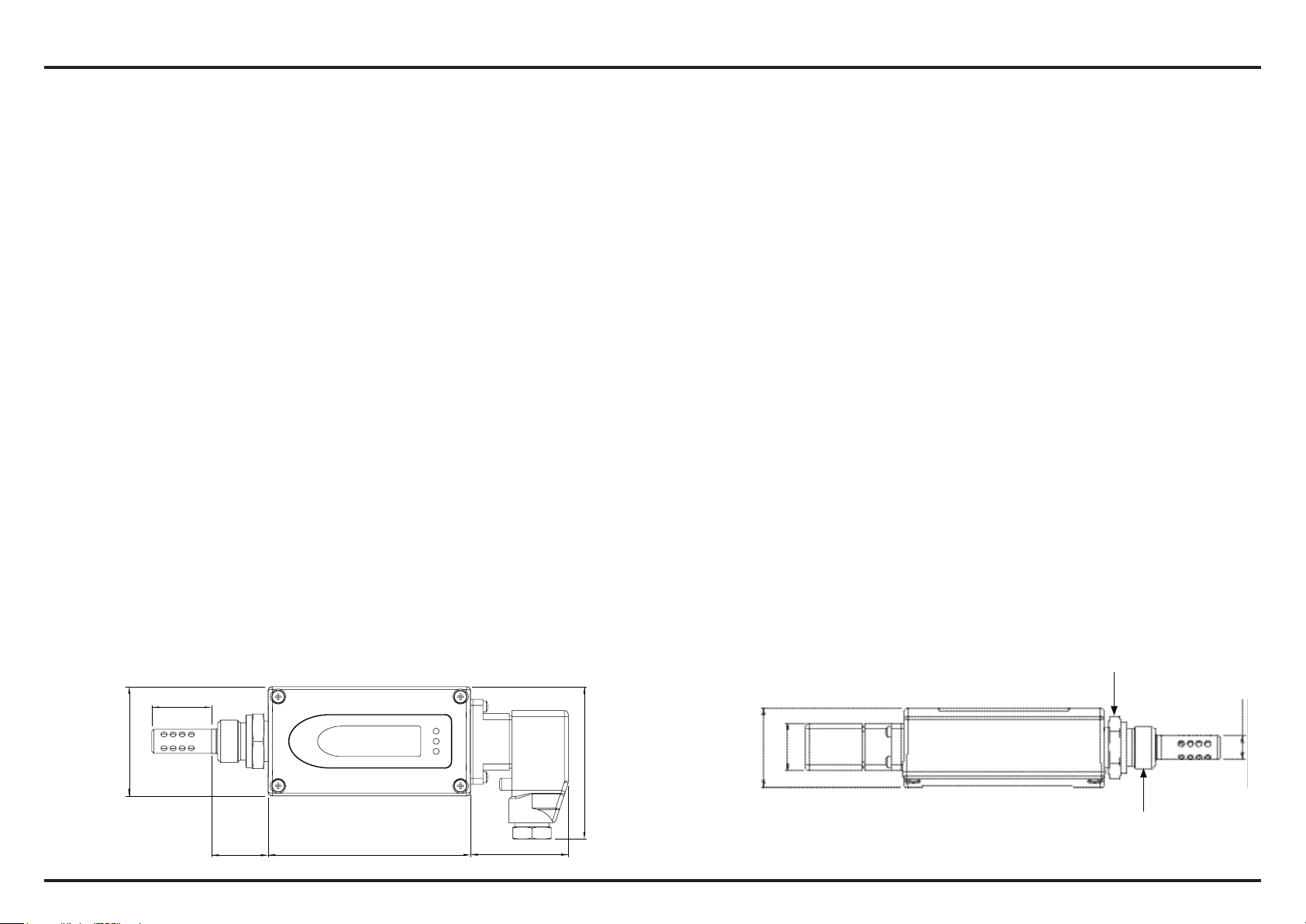
2.2 Abmessungen
32
Schlüsselweite:
27 oder 24
54
Ø12
24
75
10028
48
Seite 7
40
G1/2” ISO oder
1/2” NPT
Page 8
Bedienungsanleitung deutsch EE381
3. INSTALLATION
3.1 Einbauort
Wählen Sie einen Ort, dessen Bedingungen eine optimale Messung des Prozesses erlauben. Das Öl muss dabei frei um das Sensorelement zirkulieren können. Installieren Sie den Messumformer daher direkt in das zirkulierende System und nicht in ein Reservoir.
3.2 Montage des Fühlers direkt im Prozess
Bei einer direkten Fühlermontage sollte an beiden Seiten des Prozesses ein Absperrventil vorgesehen werden. Der Messumformer kann
somit ohne Problem zur Wartung und Kalibrierung entnommen werden.
1. Schritt:
Montieren Sie den Fühler bei geschlossenen Absperrventilen.
Bei einem NPT 1/2“ Gewinde darf kein Dichtring verwendet werden.
Stattdessen ist ein geeignetes PTFE Dichtband oder Dichtungsmasse
zu verwenden.
2. Schritt:
Den Fühler in den Prozess einführen und mit Hand so weit als
möglich festschrauben.
3. Schritt:
Wenn vorhanden, denn Dichtring auf die richtige Zentrierung prüfen
und die Verschraubung mit einem denierten Drehmoment von 30Nm
anziehen.
Seite 8
Page 9
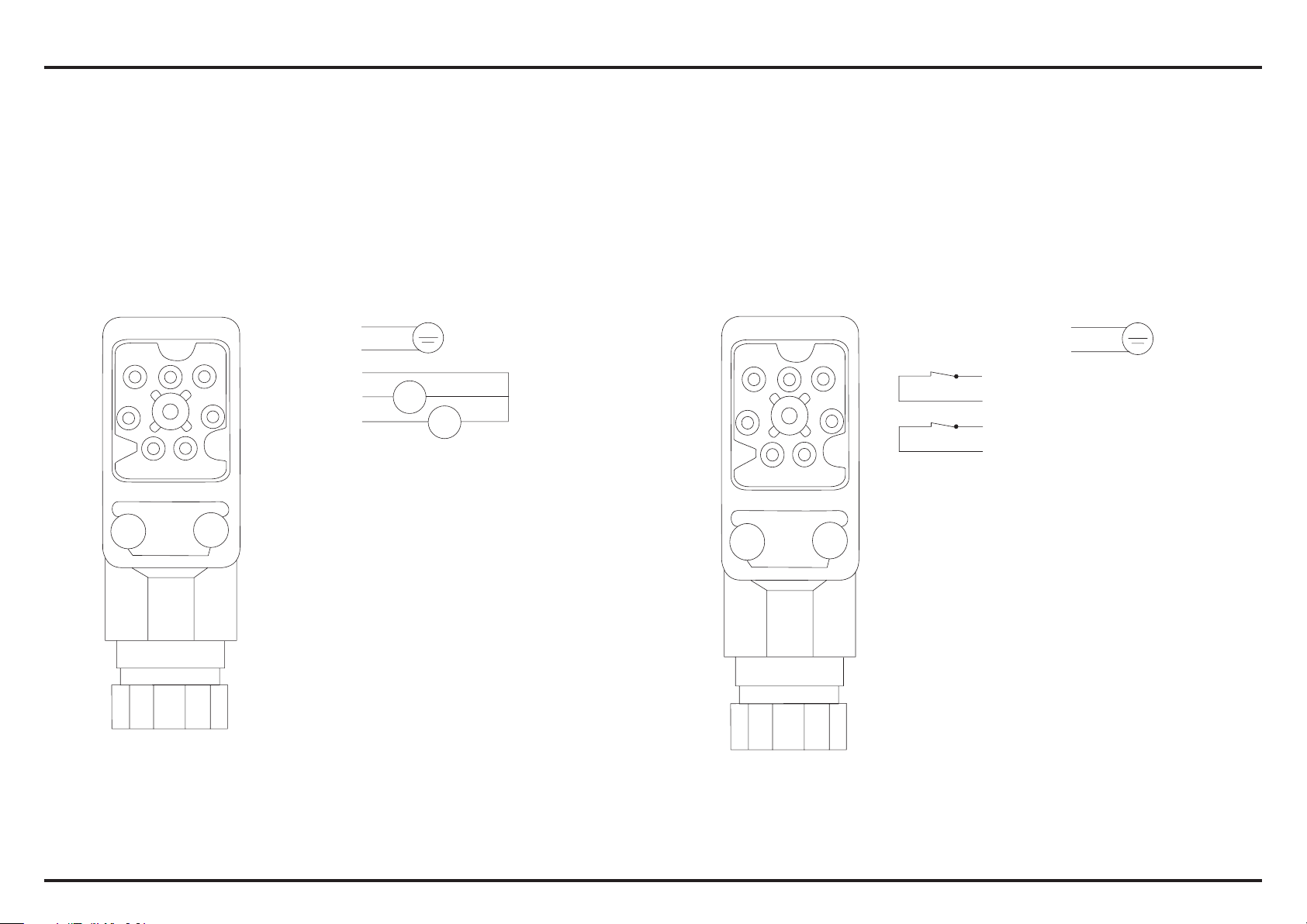
3
4
6 NC
7 NC
mA
1
7
6
5
2
3
4
1 V+
2 GND
3 NC11
4 NC12
5 NC21
6 NC22
7 not connected
10...30V DC
Bedienungsanleitung deutsch EE381
4. ELEKTRISCHE ANSCHLÜSSE
Analogausgang: Schaltausgang:
1 V+
10...30V DC
2 GND
6
5
4
1
7
2
3
3 GND
4 OUT1
5 OUT2
6 NC
7 NC
V
mA
V
mA
Seite 9
Page 10
Bedienungsanleitung deutsch EE381
12
NC
NC
21
21
NC
NC
22
22
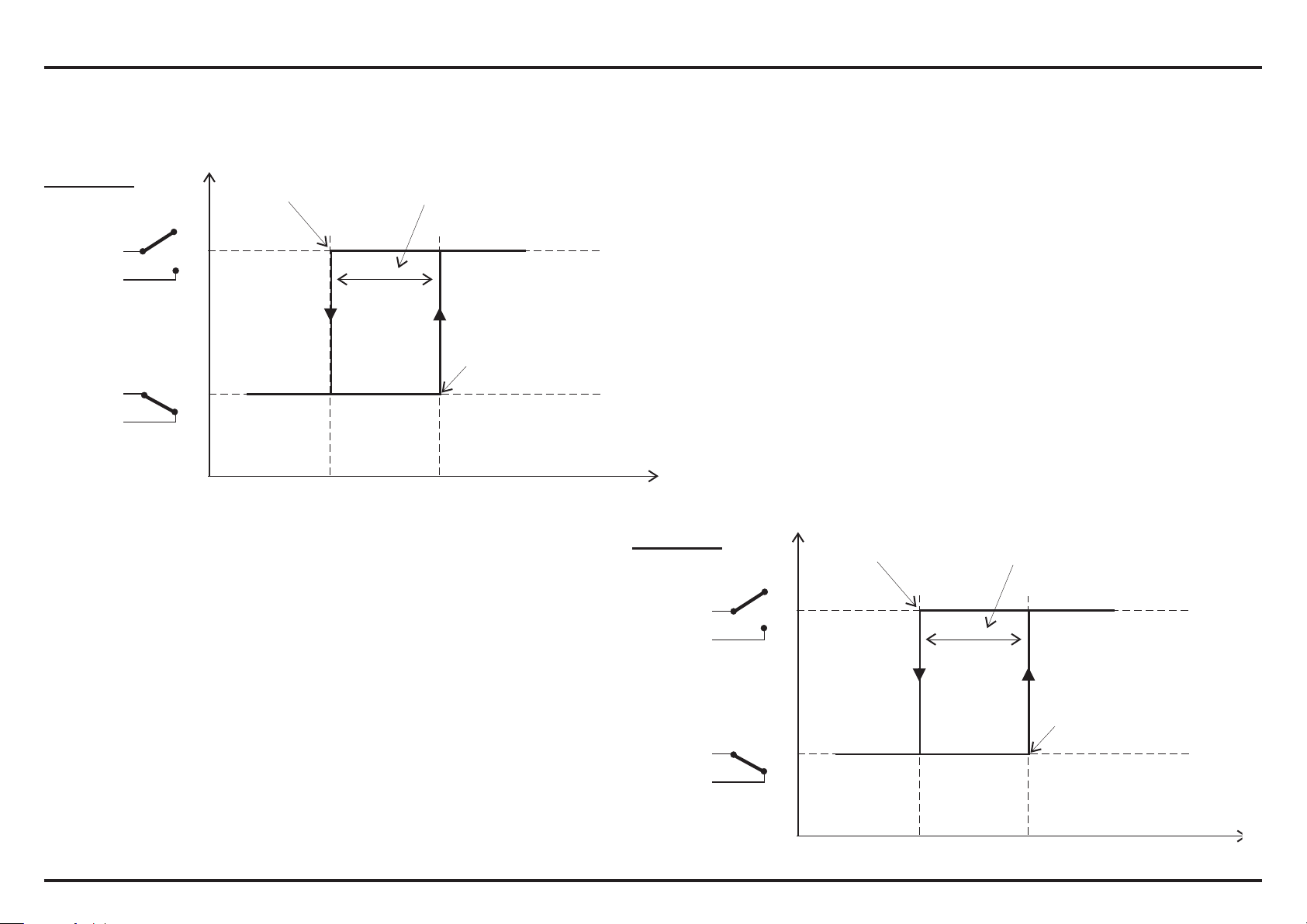
Die Schaltschwellen sind ab Werk wie folgt eingestellt:
RELAIS 1:
NC
11
EINAUS
12
NC
NC
11
NC
Ausschaltpunkt
Relais Status
Hysterese
0,05 a
w
0,75 0,8
Einschaltpunkt
] Schaltpunkt
[a
w
RELAIS 2:
21
NC
EINAUS
22
NC
Ausschaltpunkt
Relais Status
0,05 a
Hysterese
w
21
22
Seite 10
NC
NC
0,85 0,9
Einschaltpunkt
] Schaltpunkt
[a
w
Page 11
Bedienungsanleitung deutsch EE381
I
U
I
U
I
U
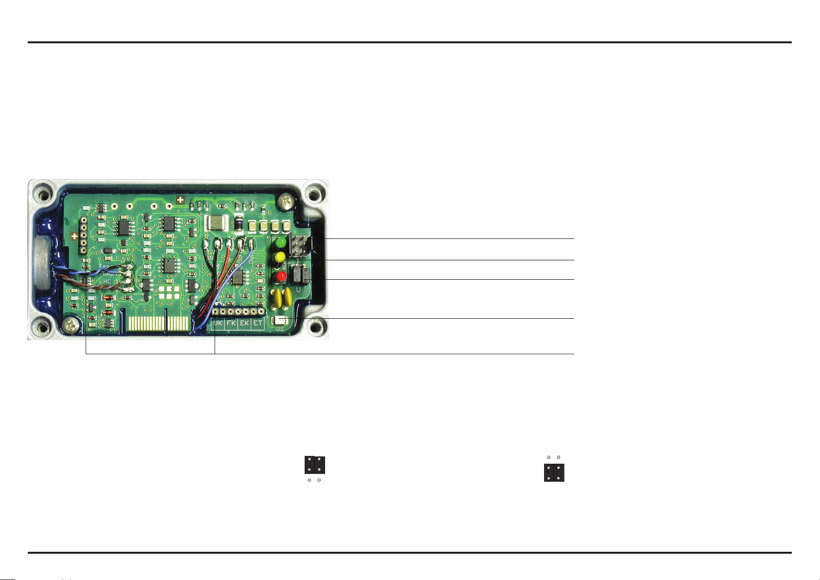
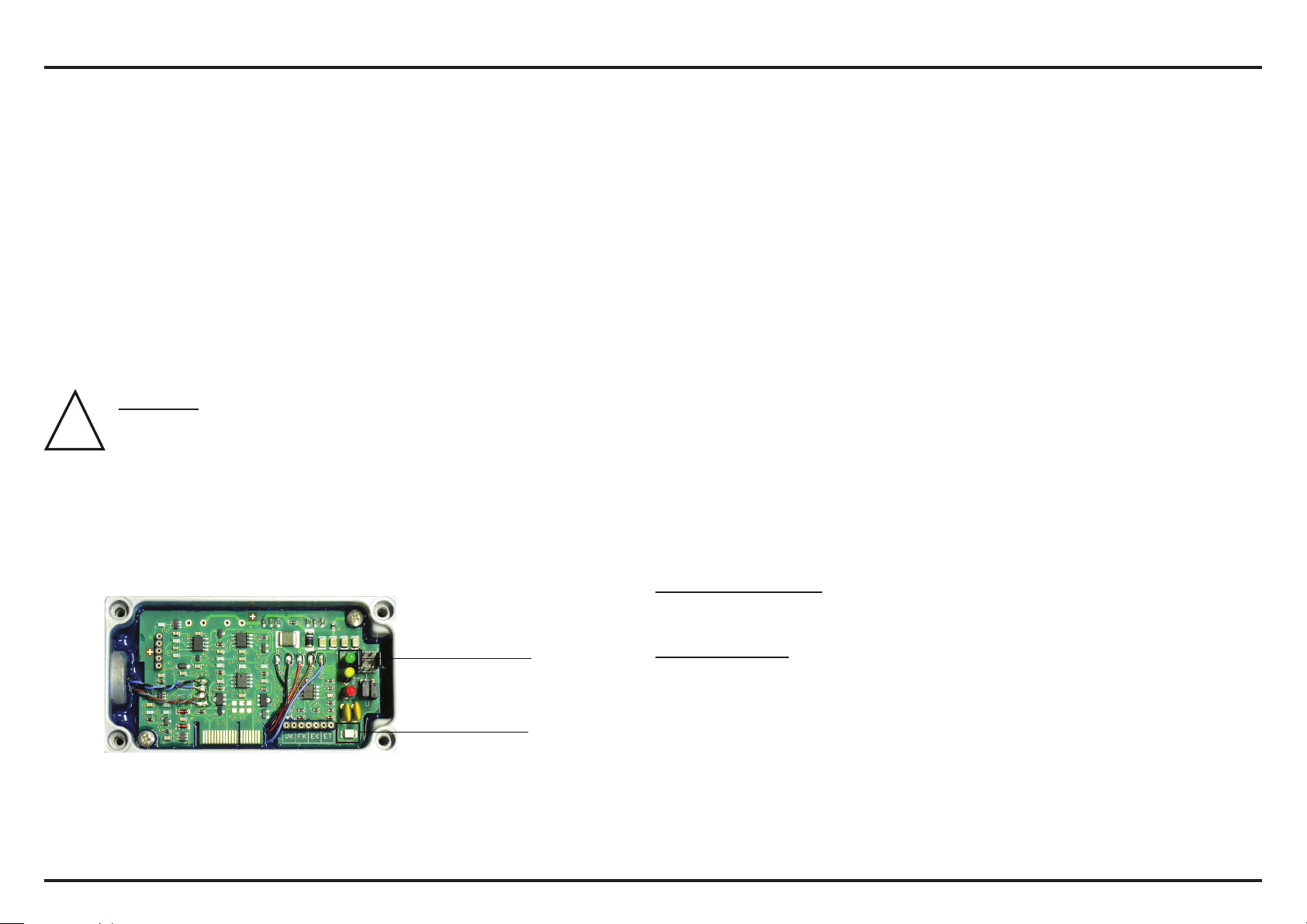
5. BEDIENUNGSELEMENTE
5.1 Platine
Nach Entfernen des Gehäusedeckels sind auf der Platine folgende Bedienelemente zur Anpassung des Messwertgebers an die
gewünschte Konguration zugänglich:
1. Serielle Schnittstelle
2. Status LED‘s
3. Strom-/Spannungsausgang
4. Diagnose LED
5. Display
1. Serielle Schnittstelle: Stecker für serielles Schnittstellenkabel (HA010604).
2. Status LED‘S: Geben über den Status des Gerätes Auskunft. Siehe Kapitel „5.2 Status LED‘s.
3. Strom-/Spannungsausgang: Wird mit Hilfe der Kongurationssoftware das Gerät von Strom- auf Spannungsausgangssignal
umgestellt, so müssen zusätzlich 2 Jumper wie folgt positioniert werden:
für Stromsignale: für Spannungssignale:
4. Diagnose LED: Optischer Hinweis zur einfachen Bestimmung der Fehlerursache (siehe Kapitel “6.2 Selbstdiagnose und
Störmeldungen”).
5. Display: Diese Steckplätze dienen zur Aufnahme des Anzeige Moduls.
Seite 11
Page 12
Bedienungsanleitung deutsch EE381
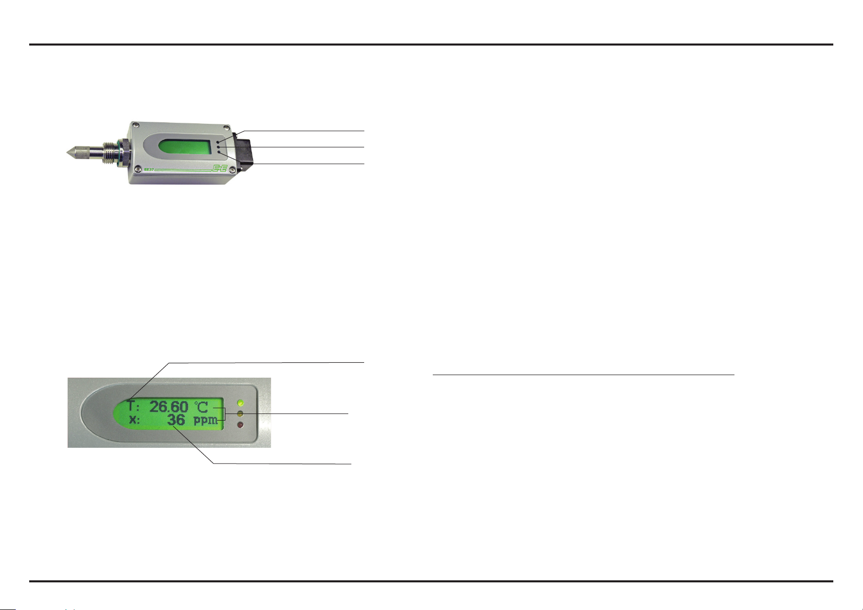
5.2 Status LED’s
Grün (Power LED): blinkt => Versorgungsspannung angelegt
Grün
Gelb
Rot
Gelb / Rot: Die gelbe und rote LED ist nur beim Modell S
(Schalter) aktiviert:
- Leuchtet Gelb: Voralarm Relais 1
- Leuchtet Rot: Hauptalarm Relais 2
Beim Modell T (Transmitter) sind die gelbe und
rote LED deaktiviert und haben keine Funktion.
5.3 Anzeigemodul (Option)
Messgrößen
Einheiten
Messwert
Messgrößen: Einheiten:
SI US
T Temperatur °C °F
Wasseraktivität
a
w
x Wassergehalt ppm ppm
Seite 12
Page 13
Bedienungsanleitung deutsch EE381
!
6. INSTANDHALTUNG
6.1 Sensorreinigung
Die Reinigung des Messkopfes wird besonders vor dem Einbringen in ein anderes Öl bzw. vor einer Kalibration empfohlen.
Das Sensorelement darf während des gesamten Reinigungsvorgangs nicht berührt oder abgewischt werden!
Reinigung des Sensors von Ölrückständen:
1) Messkopf ca. 30 Sekunden n-Heptan schwenken
2) Abtropfen lassen, ca. 30 min. ablüften lassen
Achtung:
Es wird dringend geraten, NICHT zu versuchen, die Verschmutzung auf mechanischem Weg, zum Beispiel mit Wattestäbchen oder
Baumwolllappen, vom Sensor zu entfernen!
6.2 Selbstdiagnose und Störmeldungen
Selbstdiagnose durch LED auf der Platine: Power LED (grün):
- blinkt => Versorgungsspannung angelegt / Mikroprozessor läuft
LED D1 (blau):
- leuchtet => Sensor Element beschädigt
- blinkt => Sensor Element betaut (Kondensation)
Störmeldungen am Display (optional): - Error 1 => Feuchte Sensor Element beschädigt
- Error 2 => Feuchte Sensor Element betaut (Kondensation)
- Error 3 => Temperatur Sensor Element beschädigt
- Error 4 => Kurzschluss Temperatur Sensor
Power LED grün
LED D1 blau
Seite 13
Page 14

Bedienungsanleitung deutsch EE381
i
Weitere Selbstdiagnosen:
Denition:
• Fehler:
- mögliche Ursache
=> Maßnahme / Abhilfe
• Display zeigt falsche Werte:
- Fehler bei Neujustage des Messumformers
=> Rücksetzen auf Werkskalibration und wiederholen
der Kalibrationsroutine
- Ausgang falsch konguriert
=> Abbildungsbereich und Ausgangssignale in der
Kongurationssoftware prüfen
• Ausfall des Messumformers:
- keine Versorgungsspannung
=> Zuleitung und Versorgungsspannung überprüfen
=> nur grüne LED leuchtet ständig => Elektronik defekt
=> an den Hersteller wenden
Seite 14
Page 15

Bedienungsanleitung deutsch EE381
-40 -30 -20 -10 0 10 20 30 40 50 60 70 80
0.4
0.3
0.2
0.1
0
-0.1
-0.2
-0.3
-0.4
7. ERSATZTEILE / ZUBEHÖR
- Edelstahllter (HA010110)
- Display (D08)
- Kongurationssoftware + Schnittstellenkabel (HA010604)
8. TECHNISCHE DATEN
Messwerte
Wasseraktivität
Feuchtesensor HMC01
Messbereich 0...1a
Genauigkeit inkl. Hysterese und Nichtlinearität in Luft ±0,02aw (0...0,9aw) ±0,03aw (0,9...1aw)
Temperaturabhängigkeit für aw: ±(0,00022 + 0,0002 x aw) x DT [°C] DT = T - 20°C
für T: ±(0,0003°C/°C)
Ansprechzeit mit Edelstahllter bei 20°C / t90 typ. 10min bei ruhendem Öl
Temperatur
Temperatursensor HMC01
Einsatzbereich Messfühler -40...120°C
Genauigkeit
D°C
w
°C
Seite 15
Page 16

Bedienungsanleitung deutsch EE381
Ausgänge
EE381-Tx zwei frei wähl- und skalierbare 0 - 1V / 0 - 5V / 0 - 10V1) -1mA < IL < 1mA
Analogausgänge für aw, T, ppm 4 - 20mA / 0 - 20mA RL < 500 Ohm1)
EE381-Sx Schaltausgang 2 potentialfreie Relais (NC) 30V DC 0,6A / 35V AC 0,3A (resistiv)
Standardeinstellung der Schaltausgänge Voralarm: 0,8 a
w
Hauptalarm: 0,9 aw
Hysterese: 0,05 a
w
Allgemein
Versorgungsspannung 10...30V DC
Stromverbrauch bei 24V DC Spannungsausgang: typ. 40mA / bei Autokalibration: 100mA
Stromausgang: typ. 80mA / bei Autokalibration: 140mA
Druckeinsatzbereich 0...20bar/ 0...100bar
Systemvoraussetzungen für Software ab WINDOWS 2000; serielle Schnittstelle
Serielle Schnittstelle für Konguration RS232C
Gehäuse / Schutzklasse Al Si 9 Cu 3 / IP65
Elektrischer Anschluss 7-poliger Industrie-Stecker: DIN VDE 0627 / IEC 61984
Kabel Querschnitt: 0.25 - 1 mm2 / Kabelanschluss: PG 11
Sensorschutz Edelstahllter (gelocht)
Betriebstemperaturbereich Fühler: -40...120°C
Elektronik: -40...80°C
mit LC Display: -20...50°C
Lagertemperaturbereich -40...60°C
Elektromagnetische Verträglickeit gemäß EN61326-1 EN61326-2-3
Industrieumgebung
1) min. Versorgungsspannung 15V DC
Seite 16
Page 17

Manual english EE381
!
i
1. GENERAL
This manual is a part of the scope of supply and to warrant proper handling and optimal performance of the instrument it should be read
before start-up.
In addition, the manual is for everyone who requires knowledge about transport, setup, operation, maintenance and repair.
The manual should not be used without written consent from E+E Elektronik® for the purpose of competition or forwarded to third parties.
Copies for personal use are permitted.
All information, technical data and illustrations contained in these instructions are based on information available at the time of publication.
1.1 Symbol assertion
This symbol indicates a safety instruction.
These safety instructions should always be followed carefully. By not following these instructions injuries of persons or material
damage could happen. Therefore E+E Elektronik® does not accept liability.
This symbol indicates a note.
These notes should be followed to achieve optimum functioning of the equipment.
page 17
Page 18

Manual english EE381
!
1.2 Safety instructions
General Safety Instructions
• Excessive mechanical loads and incorrect usage should always be avoided.
• Take care when unscrewing the lter cap as the sensor element could be damaged.
• The sensor is an Electro Static Discharge sensitive component (ESD). When touching the sensor element, ESD protective
measures should be followed.
• Grip sensors only at the lead wires.
• Installation, electrical connection, maintenance and commissioning should be performed by qualied personnel only.
1.3 Environmental aspects
Products from E+E Elektronik® are developed considering all important environmental issues. While disposing of the product
environmental pollution should be avoided. To dispose of the transmitter the individual components should be sorted with care.
The housing consists of metal (aluminium, Al Si 9 Cu 3). The electronic parts should be collected as electronic scrap and disposed of
according to the regulations in force.
2. PRODUCT DESCRIPTION
2.1 General
E+E Transmitter Series EE381 are specially designed for the measurement of water content in oil. EE381 is ideal for online monitoring
of moisture in lubrication or insulation oil, which is very important for the long-term performance and preventive maintenance of plant and
machinery.
page 18
Page 19

Manual english EE381
Humidity measurement in oil
Similar to the humidity in the air, the water content in oil can be indicated by the absolute value in ppm or by the relative value a
:
w
- ppm (mass of water / mass of oil)
(actual water content as fraction of the water content in saturated oil)
- a
w
= 0 corresponds to water-free oil, while aw = 1 indicates saturated oil. aw measurement with the EE381 transmitter is based on the
a
w
outstanding long term stability and resistance to pollution of the E+E capacitive sensor elements series HMC.
Model T: The transmitter has two freely selectable and scaleable outputs for water content, temperature or ppm volume
concentration.
Model S: The switch with two relay outputs is designed for control and alarm purposes. The status for early warning and main alarm is
indicated by LED‘s.
The optional conguration software allows exible and easy adjustment of the analogue resp. relay outputs to the respective
requirements. The adjustment / calibration of the transmitters can easily be performed.
An optional display for on-site monitoring of the measuring values allows for a quick overview of the prevailing conditions in the process.
2.2 Dimensions in mm (inch)
32
(1.3”)
54 (2.1”)
28 (1.1”)
100 (4”)
48 (1.9”)
75 (3”)
page 19
40 (1.6”)
spanner width:
27 or 24
Ø12 (0.5”)
24 (1”)
G1/2” ISO or
1/2” NPT
Page 20

Manual english EE381
3. INSTALLATION
3.1 Installation location
Select a location that offers optimum measuring conditions. The oil must be able to circulate freely around the sensing element.
Mount the transmitter directly into the circulating system and not into a reservoir.
3.2 Installing the probe directly into the process
When installing a probe directly into the process, there should be a stop valve on both sides of the point of installation.
This makes it easy to remove the transmitter for maintenance and calibration.
Step 1:
Install the probe with the stop valves closed.
It is not permitted to use a sealing ring with a NPT 1/2“ thread.
Appropriate PTFE sealing tape or sealant should be used instead.
Step 2:
Insert the probe into the process and screw it as tight as possible by hand.
Step 3:
If there is a sealing ring, check it for correct centring and tighten the
screw connection with a torque of 30 Nm.
page 20
Page 21

3
4
6 NC
7 NC
mA
1
7
6
5
2
3
4
1 V+
2 GND
3 NC11
4 NC12
5 NC21
6 NC22
7 not connected
10...30V DC
Manual english EE381
4. ELECTRICAL CONNECTIONS
Analogue output: Relay output:
1 V+
10...30V DC
2 GND
6
5
4
1
7
2
3
3 GND
4 OUT1
5 OUT2
6 NC
7 NC
V
mA
V
mA
page 21
Page 22

Manual english EE381
NC
NC
21
21
NC
NC
22
22
The switching thresholds are factory set:
RELAY 1:
NC
11
ONOFF
12
NC
NC
11
12
NC
switching off
relay status
hysterese
0.05 a
w
0.75 0.8
switching on
] switching point
[a
w
RELAY 2:
21
ONOFF
22
NC
NC
switching off
relay status
0.05 a
hysterese
w
21
22
page 22
NC
NC
0.85 0.9
switching on
[a
] switching point
w
Page 23

Manual english EE381
I
U
I
U
I
U
5. OPERATING COMPONENTS
5.1 Circuit board
After removal of the housing cover, the following operating components on the circuit board may be accessed to congure the transmitter to the desired settings:
1. Serial interface
2. Status LED‘s
3. Current-/ voltage output
4. Diagnostic LED
5. Display
1. Serial interface: Pin connector for serial interface cable (HA010604).
2. Status LEDs: Provide information about the status of the device. Refer to chapter „5.2 Status LEDs.
3. Current-/ voltage output: If the transmitter is switched from current to voltage output, using the conguration software, the 2 jumpers
must be positioned accordingly:
for current signals: for voltage signals:
4. Diagnostic LED: Visual indication for easy determination of the cause of error. (refer to chapter “6.2 Self-diagnostic and
error messages”).
5. Display: These pin connecters are designated for the display module.
page 23
Page 24

Manual english EE381
5.2 Status LED’s
Geen (Power LED): ashing => supply voltage applied
Green
Yellow
Red
Yellow / Red: The yellow and red LEDs are only activated
with model S (switch):
- yellow lit constantly: early warning relay 1
- red lit constantly: main alarm relay 2
With model T (transmitter) the yellow and red
LEDs are deactivated and have no function.
5.3 Display Module (Option)
Measurand
Units
Measured value
Measurand: Units:
SI US
T Temperature °C °F
Water activity
a
w
x Water content ppm ppm
page 24
Page 25

Manual english EE381
!
6. MAINTENANCE
6.1 Sensor cleaning
Cleaning of the measuring head is recommended before emerging in other oil and prior to calibration.
Do not touch or rub the sensing element during the cleaning process!
Cleaning of sensor from oil residue:
1) Emerge the measuring head in N-HEPTAN and swirl for approx. 30 seconds
2) Remove excess liquid and allow to air dry for approx. 30 minutes
Warning:
It is strongly advised NOT to try cleaning the sensor by mechanical means, such as rubbing the sensor with cotton material!
6.2 Self-diagnostic and error messages
Self-diagnostic via LED on the circuit board: Power LED (green):
- ashing => Supply voltage applied / Microprocessor is active
LED D1 (blue):
- constantly lit => sensor element damaged
- ashing => sensor element bedewed (condensation)
Self-diagnostic via display (option): - Error 1 => Humidity sensor element damaged
- Error 2 => Humidity sensor element bedewed (condensation)
- Error 3 => Temperature sensor element damaged
- Error 4 => Short circuit of temperature sensor
Power LED green
LED D1 blue
page 25
Page 26

Manual english EE381
i
Continuing self-diagnostic:
Denition:
• Error:
- possible cause
=> measures / help
• Display shows incorrect values:
- Error during re-adjustment of the transmitter
=> Reset to factory calibration and repeat the
calibration routine
- Output congured incorrectly
=> Check output range and output signals
in the conguration
• Transmitter failure:
- No supply voltage
=> Check wiring and supply voltage
=> Only green LED is illuminated continuously => electronics
defect => contact the manufacturer
page 26
Page 27

Manual english EE381
-40 -30 -20 -10 0 10 20 30 40 50 60 70 80
0.4
0.3
0.2
0.1
0
-0.1
-0.2
-0.3
-0.4
7. REPLACEMENT PARTS / ACCESSORIES
- stainless steel grid (HA010110)
- display (D08)
- conguration software + interface cable (HA010604)
8. TECHNICAL DATA
Measuring values
Water activity
Humidity sensor HMC01
Measuring range 0...1a
Accuracy incl. hysteresis and nonlinearity in air ±0.02aw (0...0.9aw) ±0.03aw (0.9...1aw)
Traceable to intern. standards, administrated by NIST, PTB, BEV...
Temperature dependence aw: ±(0.00022 + 0.0002 x aw) x DT [°C] DT = T - 20°C
T: ±(0.0003°C/°C)
Response time with stainless steel lter at 20°C / t90 typ. 10min in still oil
Temperature
Temperatur sensor element HMC01
Working range sensing probe -40...120°C (-40...248°F)
Accuracy
D°C
page 27
w
°C
Page 28

Manual english EE381
Outputs
EE381-Tx two freely selectable and scaleable 0 - 1V / 0 - 5V / 0 - 10V1) -1mA < IL < 1mA
analogue outputs for aw, T, ppm 4 - 20mA / 0 - 20mA RL < 500 Ohm1)
EE381-Sx alarm output 2 potential-free relays (NC)
30V DC 0.6A / 35V AC 0.3A (resisitve)
Standard setting of alarm outputs pre-alarm: 0.8 a
w
main alarm: 0.9 aw
hysteresis: 0.05 a
w
General
Supply voltage 10...30V DC
Current consumption at 24V DC voltage output: typ. 40mA / during autocalibration: 100mA
current output: typ. 80mA / during autocalibration: 140mA
Pressure range 0...20bar (0...290psi) / 0...100bar (0...1450psi)
System requirements for software WINDOWS 2000 or later; serial interface
Serial interface for conguration RS232C
Housing / Protection class Al Si 9 Cu 3 / IP65; Nema 4
Electrical connection 7-pole industrial plug: DIN VDE 0627 / IEC 61984
cable cross-section: 0.25 - 1 mm2 / cable connection: PG 11
Sensor protection stainless steel lter (punched)
Working temperature range probe: -40...120°C (-40...248°F)
electronic: -40...80°C (-40...176°F)
with LC display: -20...50°C (-4...122°F)
Storage temperature range -40...60°C (-40...140°F)
Electromagnetic compatibility according to EN 61326-1 EN61326-2-3 ICES-003 ClassB
Industrial Environment FCC Part15 ClassB
1) minimum supply voltage 15V DC
page 28
Page 29

Manuel français EE381
!
i
1. GENERALITES
Le manuel d‘instruction est un élément de la livraison et permet d‘obtenir une utilisation appropriée et un fonctionnement optimal de
l‘instrument.
Pour cette raison, le manuel d‘instruction doit obligatoirement être consulté avant toute mise en service.
De plus, ce manuel d‘instruction doit être transmis à chaque personne devant s‘occuper du transport, de l‘installation, de l‘utilisation, de la
maintenance et de la réparation de l‘appareil.
Ce manuel d‘instruction ne peut être utilisé par la concurrence ou transmis à un tiers, sans accord écrit préalable de E+E Elektronik
Toute copie pour besoins personnels est autorisée.
Les informations contenues dans ce document sont périodiquement modiées et ne peuvent se substituer à celles du service des
modications. Le fabricant se réserve le droit de modier ou remanier à tout moment les produits décrits.
®
.
1.1 Description des symboles
Ce symbole indique des points de sécurité à respecter.
Les consignes de sécurité doivent être respectées. Des blessures corporelles ou des dégradations matérielles peuvent être
®
causées par le non-respect des consignes. E+E Elektronik
Ce symbole indique une remarque.
Pour un fonctionnement optimal de l‘appareil ces points d‘informations doivent être pris en compte.
ne peut en être tenu pour responsable.
page 29
Page 30

Manuel français EE381
!
1.2 Consignes de sécurité
Consignes de sécurité générales
• Toute sollicitation mécanique extrême et incorrecte doit obligatoirement être évitée.
• Lors du dévissage du ltre, veiller à ne pas endommager le capteur de mesure.
• Les mesures de protection liées aux risques d‘électricité statique doivent être respectées lors de tout contact avec le capteur de
mesure.
• Manipuler le capteur uniquement par les ls de connexions
• Le montage, le raccordement électrique, la maintenance et la mise en service ne doivent être effectués que par du personnel
qualié.
1.3 Aspects environnementaux
Tous les produits de E+E Elektronik® sont conçus en tenant compte des contraintes environnementales. En cas de mise au rebut, une
attention particulière sera portée sur les risques de pollution.
Pour la mise au rebut, une séparation des différents composants doit être effectuée. Le boîtier est constitué de métal (Al Si 9 Cu 3)
recyclable. L‘électronique doit être éliminée avec les déchets électroniques.
2. DESCRIPTION DU PRODUIT
2.1 Généralités
Les transmetteurs de la série EE381 ont été spécialement développés pour la détermination de la quantité d‘eau contenue dans l‘huile. Ils
autorisent la surveillance en continue de la quantité d‘eau dans les huiles de lubrication ou d‘isolation et délivrent ainsi une information
importante sur le bon fonctionnement à long terme des machines et des installations.
page 30
Page 31

Manuel français EE381
Quantité d‘eau dans l‘huile
Par analogie à l‘humidité dans les gaz, l‘humidité de l‘huile peut être exprimée en absolue, en ppm ou en relative par l‘activité de l‘eau
:
a
w
- ppm (masse d‘eau / masse d‘huile)
(quantité d‘eau actuelle en relation à la quantité d‘eau d‘un échantillon saturé)
- a
w
Une huile sans aucune particule d‘eau a une valeur a
de 0 et une huile saturée d‘eau a une valeur aw de 1. Les transmetteurs de la série
w
EE381 équipés du capteur capacitif HMC de E+E stable à long terme et résistant chimiquement, déterminent toujours l‘activité de l‘eau
.
a
w
Modèle T: Le transmetteur dispose de deux sorties librement congurables et étalonnables pour l’activité de l’eau a
, la température
w
T ou la quantité d’eau dans l’huile en ppm.
Modèle S: Deux sorties relais sont disponibles pour des systèmes de contrôle ou de surveillance des seuils d‘alarme. L‘état
de pré-alarme et d‘alarme est visualisé par les LED.
Le logiciel de conguration livré en option permet d’adapter aisément les sorties analogiques et relais à vos besoins. Le réglage / la calibration du transmetteur est ainsi facilement réalisable.
L‘afcheur disponible en option permet la visualisation instantanée des valeurs de mesure de l‘appareil en fonctionnement dans le process.
2.2 Dimensions
32
clé plate:
27 ou 24
54
Ø12
24
75
4810028
page 31
40
1/2” G ISO ou
1/2” NPT
Page 32

Manuel français EE381
3. INSTALLATION
3.1 Lieu d‘installation
Choisir un lieu d‘installation où les conditions permettront une mesure optimale de l‘appareil. L‘huile doit pouvoir circuler librent autour
de l‘élément sensible. Le transmetteur doit donc être installé directement dans le système de circulation contenant l‘huile et non dans un
réservoir.
3.2 Montage de la sonde directement sur le process
Pour un montage direct de la sonde, une vanne d‘arrêt doit être prévue de chaque côté du process. Le transmetteur peut ainsi être retiré
sans difculté an d‘effectuer l‘entretien ou la calibration de l‘appareil.
Etape 1:
La sonde doit être montée avec les vannes d‘arrêt fermées.
Aucun joint ne doit être utilisé avec un raccord étanche1/2“ NPT.
Mais il est nécessaire d‘utiliser un ruban TEFLON ou une pâte
d‘étanchéité adaptée.
Etape 2:
La sonde doit être intégrée dans le process et vissée à la main
aussi fermement que possible.
Etape 3:
Vérier le bon positionnement de l‘appareil et exercer une rotation
du système d‘étanchéité si nécessaire. Puis serrer l‘écrou avec un
couple de serrage de 30Nm.
page 32
Page 33

3
4
6 NC
7 NC
mA
1
7
6
5
2
3
4
1 V+
2 GND
3 NC11
4 NC12
5 NC21
6 NC22
7 not connected
10...30V DC
Manuel français EE381
4. RACCORDEMENT ELECTRIQUE
Sortie analogique: Sortie relais:
1 V+
10...30V DC
2 GND
6
5
4
1
7
2
3
3 GND
4 OUT1
5 OUT2
6 NC
7 NC
V
mA
V
mA
page 33
Page 34

Manuel français EE381
12
NC
NC
21
21
NC
NC
22
22
Les seuils des sorties relais sont congurés en usine comme suit:
RELAIS 1:
NC
11
12
NC
ENCLENCHEMENTDECLENCHEMENT
NC
11
NC
Seuil de déclenchement
Status relais
0,75 0,8
0,05 a
Hystérésis
w
Seuil d‘enclenchement
Seuil [a
RELAIS 2:
]
w
21
22
NC
NC
Seuil de déclenchement
Status relais
0,05 a
Hystérésis
w
ENCLENCHEMENTDECLENCHEMENT
NC
21
22
NC
page 34
0,85 0,9
Seuil d‘enclenchement
Seuil [a
]
w
Page 35

Manuel français EE381
I
U
I
U
I
U
5. COMPOSANTS DE FONCTIONNEMENT
5.1 Carte
Après avoir ôter le capot du boîtier, les composants de fonctionnement sont accessibles sur la carte pour que l‘utilisateur congure les
valeurs de mesures souhaitées.
1. Interface série
2. LED d‘indication d‘état
3. Sortie tension/courant
4. LED de diagnostic
5. Afcheur
1. Interface série: Logiciel de conguration + câble interface (HA010604).
2. LED d‘indication d‘état: Donne des indications sur l‘état de l‘appareil. Voir chapitre „5.2 LED d‘indication d‘état“.
3. Sortie tension/courant: Le logiciel de conguration permet de changer le signal de sortie courant en tension. Les deux cavaliers
doivent être positionnés comme suit:
signal courant: signal tension:
4. LED de diagnostic: Indication visuelle pour déterminer facilement la cause d‘une erreur (voir chapidre “6.2 Autodiag-
nostic et message d‘erreur”).
5. Afcheur: Cet emplacement est prévu pour l‘intégration d‘un afcheur optionnel.
page 35
Page 36

Manuel français EE381
5.2 LED d‘indication d‘état
vert (LED power): clignote => alimentation connectée
vert
jaune
rouge
jaune/rouge: Les LED jaune et rouge ne sont activées que
pour le modèle S avec les sorties relais:
- jaune allumé: pré-alarme relais 1
- rouge allumé: alarme principale relais 2
Pour le modèle T (transmetteur) les LED jaune
et rouge sont désactivées et n‘ont aucune
fonction.
5.3 Afcheur (option)
Valeurs de mesure
Unités
Valeurs mesurées
Valeurs de mesure: Unités:
SI US
T Température °C °F
Activité de l‘eau
a
w
x Quantité d‘eau dans huile ppm ppm
page 36
Page 37

Manuel français EE381
!
6. MAINTENANCE
6.1 Nettoyage du capteur
Il est recommandé de nettoyer la tête de la sonde avant de la plonger dans des huiles différentes ou de réaliser une calibration
Durant le processus de nettoyage, l‘élément sensible ne doit pas être touché ni enlevé!
Elimination des traces d‘huile sur le capteur:
1) Plonger la tête de la sonde env. 30 secondes dans une solution de n-Heptan
2) Laisser sécher pendant env. 30 min. à l‘air libre
Attention:
N’utiliser aucun moyen mécanique (par ex. bout de coton ou chiffon) pour le nettoyage an de ne pas endommager la couche
active du capteur!
6.2 Auto-diagnostic et messages d‘erreurs
Auto-diagnostic via la LED sur la carte: LED power (vert):
- clignote => alimentation connectée / microprocesseur en fonction
LED D1 (bleu):
- allumée => capteur endommagé
- clignote => condensation sur le capteur d‘humidité
Messages d‘erreur sur l‘afcheur (optionnel): - Erreur 1 => capteur d‘humidité endommagé
- Erreur 2 => condensation sur le capteur d‘humidité
- Erreur 3 => capteur de température endommagé
- Erreur 4 => court-circuit sur l‘entrée température
LED power vert
LED D1 bleu
page 37
Page 38

Manuel français EE381
i
Autres auto-diagnostics:
Dénition:
• Erreur:
- origine possible
=> mesures / actions
• Valeurs erronées sur l‘afcheur:
- Erreur lors de l‘ajustage de l‘appareil
=> Retour à la conguration usine et répéter le processus de
calibration
- Erreur de conguration de la sortie
=> Vérier l‘échelle et le signal de sortie avec le logiciel de
conguration
• Transmetteur défectueux:
- pas d‘alimentation
=> vérication du câblage et de l‘alimentation
=> seule la LED verte est éclairée => électronique défectueuse
=> retour au fabricant
page 38
Page 39

Manuel français EE381
-40 -30 -20 -10 0 10 20 30 40 50 60 70 80
0.4
0.3
0.2
0.1
0
-0.1
-0.2
-0.3
-0.4
7. PIECES DE RECHANGE / ACCESSOIRES
- Filtre inox (HA010110)
- Afcheur (D08)
- logiciel de conguration + câble interface (HA010604)
8. CARACTERISTIQUES TECHNIQUES
Données mesurées
Activité de l’eau
Capteur HMC01
Gamme de mesure 0...1a
Erreur de justesse incluant hystérésis et
non linéarité dans l‘air ±0,02aw (0...0,9aw) ±0,03aw (0,9...1aw)
Inuence de la température pour aw: ±(0,00022 + 0,0002 x aw) x DT [°C] DT = T - 20°C
pour T: ±(0,0003°C/°C)
Temps de réponse avec ltre inox à 20°C / t90 typ. 10mn avec de l‘huile statique
Température
Capteur HMC01
Gamme d‘utilisation de la sonde -40...120°C
Erreur de justesse
D°C
w
°C
page 39
Page 40

Manuel français EE381
Sorties
EE381-Tx deux sorties analogiques librement 0 - 1V / 0 - 5V / 0 - 10V1) -1mA < IL < 1mA
sélectables et congurables pour a
, T, ppm 4 - 20mA / 0 - 20mA RL < 500 Ohm1)
w
EE381-Sx sortie alarme 2 sorties relais librement congurables (NC)
30V DC 0,6A / 35V AC 0,3A (résistif)
Conguration standard des sorties alarme 1er signal d’alarme: 0,8 a
w
seuil d’alarme: 0,9 aw
hystérésis: 0,05 a
w
Généralités
Alimentation 10...30V DC
Consommation de courant à 24V DC sorties tension: typ. 40mA / pendant auto-calibration: 100mA
sorties courant: typ. 80mA / pendant auto-calibration: 140mA
Gamme de pression 0...20bars/ 0...100bars
Exigences système pour le logiciel WINDOWS 2000 ou plus récent ; interface série
Interface série pour conguration RS232C
Boîtier / Indice de protection Al Si 9 Cu 3 / IP65
Connexions connecteur industriel 7 bornes: DIN VDE 0627 / IEC 61984
section de câble: 0.25 - 1 mm2 / presse-étoupe: PG 11
Filtre de protection ltre acier inox fritté (poreux)
Gamme de température d’utilisation sonde: -40...120°C
électronique: -40...80°C
avec afcheur LCD: -20...50°C
Gamme de température de stockage -40...60°C
Compatibilité électromagnétique EN61326-1 EN61326-2-3 ICES-003 ClassB
Environnement Industriel FCC Part15 ClassB
1) alimentation minimum 15V DC
page 40
Page 41

Page 42

Page 43

Page 44

HEAD OFFICE:
E+E ELEKTRONIK Ges.m.b.H.
Langwiesen 7
A-4209 Engerwitzdorf
Austria
Tel: +43 7235 605 0
Fax: +43 7235 605 8
info@epluse.com
www.epluse.com
SALES OFFICES:
E+E CHINA / BEIJING
Tel: +86 10 84992361
info@epluse.cn www.epluse.cn
E+E CHINA / SHANGHAI
Tel: +86 21 61176129
info@epluse.cn www.epluse.cn
E+E GERMANY
Tel: +49 6172 13881 0
info@epluse.de www.epluse.de
E+E FRANCE
Tel: +33 4 7472 35 82
info@epluse.fr www.epluse.fr
E+E ITALY
Tel: +39 02 2707 8636
info@epluse.it www.epluse.it
E+E KOREA
Tel: +82 31 732 6050
info@epluse.co.kr www.epluse.co.kr
E+E USA
Tel: +1 508 530 3068
office@epluse.com www.epluse.com
 Loading...