

Page 1

Series EE33
HUMIDITY/TEMPERATURE
TRANSMITTER
BA_EE33_e // v15 // technical data are subject to change // 193359
MANUAL
Hardware and Software
Page 2

E+E Elektronik Ges.m.b.H. doesn't accept warranty and liability claims neither upon this publication nor in case of improper treatment
of the described products.
The document may contain technical inaccuracies and typographical errors. The content will be revised on a regular basis. These
changes will be implemented in later versions. The described products can be improved and changed at any time without prior notice.
© Copyright E+E Elektronik Ges.m.b.H.
All rights reserved.
EMC note USA (FCC):
This equipment has been tested and found to comply with the limits for a Class A digital device, pursuant to part 15 of the FCC
Rules. These limits are designed to provide reasonable protection against harmful interference when the equipment is operated in
a commercial environment. This equipment generates, uses, and can radiate radio frequency energy and, if not installed and used
in accordance with the instruction manual, may cause harmful interference to radio communications. Operation of this equipment in
a residential area is likely to cause harmful interference in which case the user will be required to correct the interference at his own
expense.
EMC note Canada (ICES-003):
CAN ICES-3 (A) / NMB-3 (A)
Page 3

HARDWARE
TABLE OF CONTENTS
1. GENERAL 4
1.1 Symbol assertion 4
1.2 Safety instructions 4
1.3 Environmental information 4
2. PRODUCT DESCRIPTION 5
2.1 Operating modes and conditions 5
2.2 Survey: Model / Environmental Condition / Operating mode 6
2.3 Product features EE33 6
3. MOUNTING / INSTALLATION 7
3.1 Model C (remote sensing probe up to 120°C (248°F)) 7
3.2 Model D (remote sensing probe) 8
3.3 Model E (remote sensing probe, pressure tight up to 20bar (300psi)) 9
3.4 Model I (remote sensing probe, pressure tight up to 100bar (1450psi)) 10
3.5 Model J (2 remote sensing probes, pressure tight up to 20bar (300psi)) 11
3.6 Model K (remote sensing probe, pressure tight up to 20bar (300psi)) 12
4. ELECTRICAL CONNECTIONS 13
4.1 Connection diagram 13
4.2 Connection diagram alarm module (option) 13
4.3 Connection configuration of bottom part of the housing with plug connections
8...35V DC; 12...30V AC (option C03/C07/C08) 13
4.4 Connection configuration of bottom part of the housing with integrated power supply
100...240V AC (option V01) 13
4.5 Connection configuration of connectable sensing probe (option P03) 14
5. OPERATING COMPONENTS 14
5.1 Circuit board 14
5.2 Display module (option) 15
CONFIGURATION
SOFTWARE
6. OPTIONAL MODULES (alarm module, integrated power supply, ethernet module, ARC-Module) 16
7. HUMIDITY/TEMPERATURE CALIBRATION 18
7.1 2-point humidity calibration 18
7.2 2-point temperature calibration 19
7.3 1-point humidity calibration 21
7.4 1-point temperature calibration 22
7.5 Resetting to factory calibration 23
7.6 Adjustment/Calibration EE33 model J with HUMOR 20 24
8. MAINTENANCE 25
8.1 Sensor cleaning 25
8.2 Automatic ReCover (ARC) 25
8.3 Fuse replacement 25
8.4 Self-diagnosis and error messages 26
9. NETWORK 27
9.1 RS485 network (option) 27
9.2 Ethernet - module (option) 29
10. SCOPE OF SUPPLY 33
11. REPLACEMENT PARTS / ACCESSORIES 33
12. TECHNICAL DATA 34
1. GENERAL INFORMATION 37
2. INSTALLATION 37
3. ICONS ON THE TOOLS BAR 38
3.1 File 38
3.2 Interface 38
3.3 Group 39
3.4 Transmitter 39
3.5 Information ? 40
4. ICON LIST 41
5. INDEX - INDEX CARDS 41
5.1 Analogue 41
5.2 Relay 42
5.3 Sensor / Probe replacement 43
5.4 Calibration 43
5.5 Parameter 45
5.6 Information 47
6. OVERVIEW 47
6.1 How to set-up a new transmitter? 47
6.2 How to read the configuration of a transmitter? 47
6.3 How to save the configuration in a transmitter? 47
Page 4

1. GENERAL
The manual is a part of the scope of supply and serves to ensure proper handling and
optimum functioning of the instrument. For this reason, the manual must be read before
start-up.
In addition, the manual is for all personnel who require knowledge concerning transport,
setup, operation, maintenance and repair.
The manual must not be used for the purpose of competition without a written consent
from E+E Elektronik
are permitted. All information, technical data and illustrations contained in these instructions are
based on information available at the time of publication.
1.1 Symbol assertion
This symbol indicates a safety instruction.
These safety instructions should always be followed carefully. By not following these
instructions injuries of persons or material damage could happen. Therefore
E+E Elektronik
This symbol indicates a note.
These notes should be observed to achieve optimum functioning of the equipment.
®
does not accept liability.
®
and must also not be forwarded to third parties. Copies for personal use
1.2 Safety instructions
General Safety Instructions
Excessive mechanical loads and incorrect usage should always be avoided.
•
• Take care when unscrewing the filter cap as the sensor element could be damaged.
• The sensor is an Electro Static Discharge sensitive component (ESD). When touching
the sensor element, ESD protective measures should be followed.
• Grip sensors only at the lead wires.
• Installation, electrical connection, maintenance and commissioning should be performed
by qualified personnel only.
• The devices are constructed for the operation of separated extra-low voltage (SELV).
Safety instructions for use of the alarm module with voltages >50V
To insulate the optional alarm module from the low-voltage side of the transmitter, the
•
partition provided for this purpose must be fitted in the lower section.
• During operation of the instrument the modular housing must be completely closed.
• The protection class of an opened housing corresponds to IP00 and direct contact
with components carrying dangerous voltages is therefore possible. In general, work on live
components should be avoided and when absolutely necessary, should be performed by
qualified personnel only.
Safety instructions for use of the integrated power supply (option V01)
During operation of the instrument the modular housing must be completely closed.
•
• The protection class of an opened housing corresponds to IP00. In general, work on live
components should be avoided and when absolutely necessary, should be performed by
qualified personnel only.
• The bottom part and the middle part of the housing must be grounded during operation.
1.3 Environmental aspects
Equipment from E+E Elektronik® is developed with due consideration to all resultant
environmental issues. When you dispose the equipment you should avoid environmental
pollution.
For disposal of the transmitter the individual components must be sorted with care. The
housing consists of recyclable metal (aluminium, Al Si 9 Cu 3). The electronics must be
collected as electronic scrap and disposed of according to the regulations in force.
Hardware
4
Page 5

2. PRODUCT DESCRIPTION
The EE33 series provides all the functions of a multifunctional humidity/temperature transmitter with one major difference - it is equipped with a heated measurement cell.
The heated measurement cell contains a combined (monolithic) humidity/temperature
sensor element and enables reliable long-term measurements in extremely humid or
chemically polluted environments.
With a special high-pressure probe the transmitter can be used at process pressures up
to 100bar (1450psi).
The operating modes of the heated measurement cell depend on the conditions. The
parameters of the different operating modes are as follows:
Heat intensity:
Automatic recover: The measurement cell can be heated intensively to evaporate chemical
residue or temporary condensation.
Warming: The measurement cell can be warmed slightly to prevent condensation
in environments with continuous high humidity.
Heating time:
The measurement cell can either be heated briefly (the heating time can be defined in the
configuration software) before returning to the ambient temperature or it can be warmed
continuously.
Start of heating:
Manual: Heating is started by a control element on the PCB.
Automatic: Heating is triggered when a defined humidity set point is exceeded
(configuration software).
Recurrent: Heating is recurrent and triggered after a defined cycle time (configuration
software).
Distinctive models, sensing probes and mounting versions allow for the EE33 series to be
utilized in numerous applications.
2.1 Operating modes and conditions
2.1.1 Automatic ReCover (ARC)
Chemical pollution:
When capacitive humidity sensors are exposed to chemical pollution (e.g. detergent
residue), the presence of foreign molecules can distort the measurement reading.
The foreign molecules can be evaporated by heating the measurement cell briefly and
intensively. Reconditioning helps to minimize distorted measurement readings during the
calibration interval.
Temporary condensation:
Temporary dew (e.g. in misty environments) is identified by defining a humidity set point
value (e.g. 99%) and can be evaporated by heating the measurement cell intensively for
10 seconds.
Thanks to its monolithic structure, the measurement cell cools off quickly (approx.
3 minutes) to reach once again the same humidity content as the environment.
If condensation is still detected at the end of the heating and cool-down times, the process
starts again after a defined cycle time (30 minutes).
Hardware
5
Page 6

2.1.2 Overheating / Warming (OH = Overheating)
Continuous high humidity:
Even the smallest deviation between the temperature of the sensor head and the ambient
temperature can cause dew on the sensor element in conditions of continuous high
humidity (e.g. in mushroom drying). Dew on the humidity sensor element prevents
accurate measurement of the actual humidity.
However, the EE33 series minimizes the relative humidity on the measurement cell
through regularly warming. The relative humidity and temperature of the warmed
measurement cell can be determined precisely thanks to its monolithic structure. The dew
point of the environment is calculated from the measuring values.
If the relative humidity has to be determined near condensation, the ambient
temperature can be measured with an additional temperature sensor to calculate
the relative humidity.
2.1.3 High process pressure up to 100 bar (1450psi) / high-pressure probe
(HPP = High Pressure Probe)
Thanks to the combination of the heated measurement cell with a new high-pressure
probe, the transmitter can be used in applications with high process pressure and wide
working range in humidity and temperature.
The special high-pressure probe's innovative pressure tight feed through sets it apart from
the remote probes in other models.
Special ball valves enable assembly without interrupting the process and are available on request.
2.2 Survey: Model / Environmental Condition / Operating mode
Order Code Model Environmental Conditions ARC OH HPP
EE33-MFTC remote sensing probe
(up to 120°C
(248°F))
temporary condensation, chemical pollution
EE33-MFTD remote sensing probe temporary condensation, chemical pollution
EE33-MFTE pressure tight probe temporary condensation, chemical pollution,
process pressure up to 20bar
(300psi)
EE33-MFTI high pressure probe temporary condensation, chemical pollution,
(1450psi)
(300psi)
EE33-MFTJ 2 remote sensing
probes
process pressure up to 100bar
continuous high humidity,
condensation (RH-measurement),
process pressure up to 20bar
EE33-MFTK remote sensing probe continuous high humidity,
condensation (Td-measurement),
(300psi)
EE33-PFTM 2 remote sensing
probes
process pressure up to 20bar
continuous high humidity,
condensation (RH-measurement),
2.3 Product features EE33
Functions Comment EE33
Measurement of humidity and temperature
Calculation h, r, dv, Tw, Td, Tf, e
2 freely scaleable and configurable analogue outputs
On-site adjustment for relative humidity and temperature
LED indication of transmitter status / error diagnosis of probes
RS232 for transmitter configuration via PC
Configuration software standard supply
Alternating display with MIN/MAX indication optional
2 freely configurable alarm outputs optional
Connectable sensing probe optional
Data output via RS232 interface
Data output via RS485 interface optional
RS485 für Vernetzung von bis zu 32 Geräten optional
Ethernet interface for networking and remote monitoring optional
Data logging and analysis PC software optional
ARC-Module for external triggering of sensor-heating optional
Hardware
6
Page 7
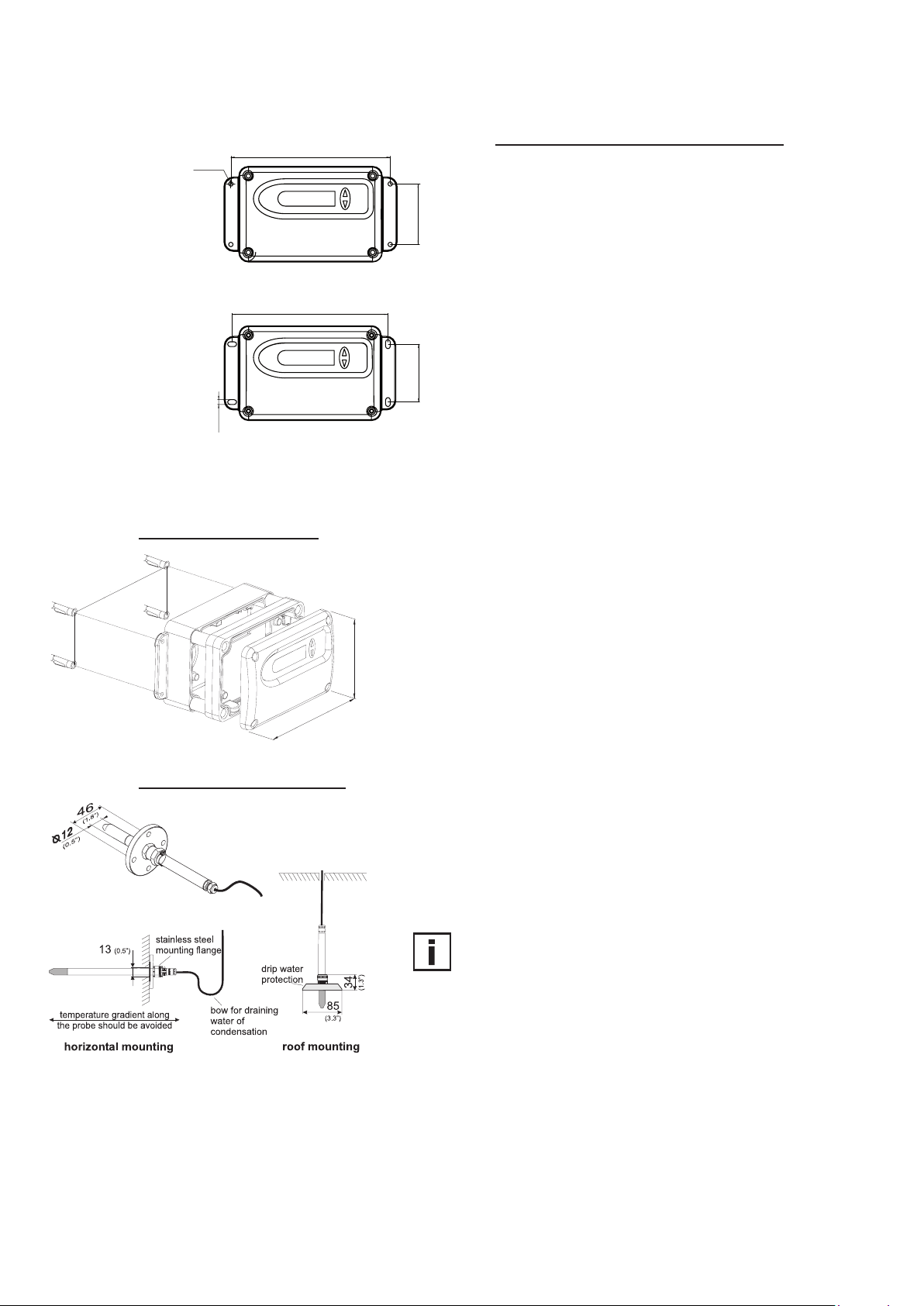
3. MOUNTING / INSTALLATION
Drilling with round hole:
150 (6”)
Ø4.2 (0.16”)
DRILLING / MOUNTING TEMPLATE:
Drill the mounting holes (with round hole or long hole)
according to the mounting template.
57 (2.24”)
Drilling with long hole:
148 (5.8”)
55 (2.16”)
4.5 (0.18”)
3.1 Model C (remote sensing probe up to 120°C (248°F))
Mounting of transmitter:
1. Drill the mounting holes according to the mounting template (see
drawing at the beginning of the chapter "Drilling/Mounting Template") .
2. The bottom part of the housing is mounted with 4
screws (screw diameter: < 4.2mm (0.2”) ; not included
in the scope of supply).
(3.5”)
90
3. Connection of the transmitter (see Hardware,
chapter 4 "Electrical connections").
(5.3”)
135
Mounting of sensing probe:
4. Mounting of the middle part and cover with 4 screws
(included in the scope of supply).
Using the stainless steel mounting flange (refer to accessories)
it is possible to mount the probe on the outer wall of the
measuring chamber.
The depth of immersion is adjustable.
For roof installations use the drip water protection (refer to
accessories) to protect the sensor head and elements against
condensed water.
The sensing probe must be mounted horizontally or vertically,
pointing downwards. When possible, a drip sheet should be
fitted for each mounting.
Working range of sensing probe: -40...120°C
(-40...248°F)
Hardware
7
Page 8
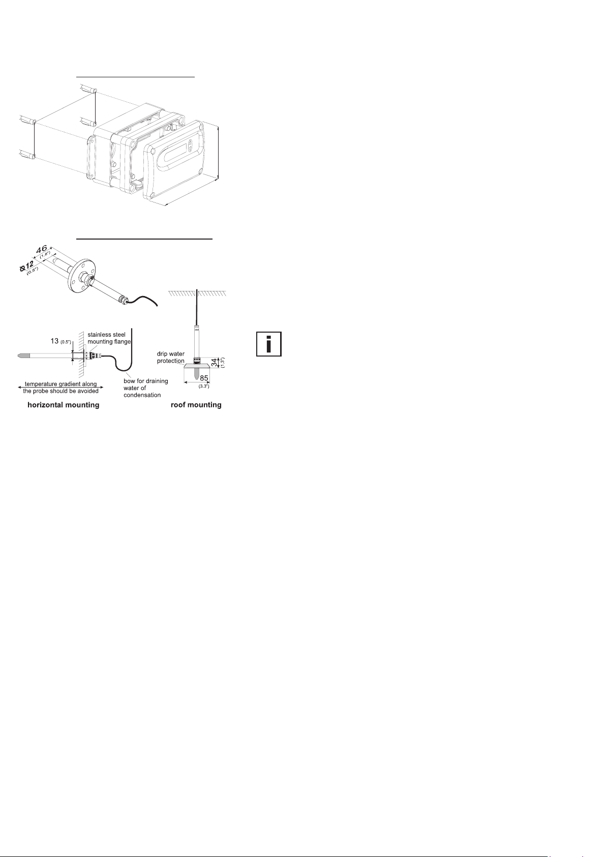
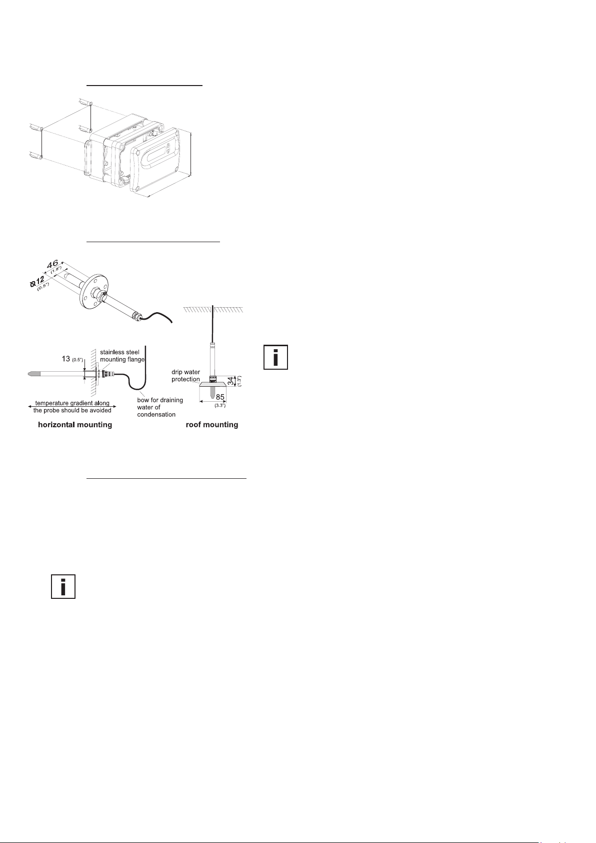
3.2 Model D (remote sensing probe)
Mounting of transmitter:
1. Drill the mounting holes according to the mounting template (see
drawing at the beginning of the chapter "Drilling/Mounting Template") .
2. The bottom part of the housing is mounted with 4
screws (screw diameter: < 4.2mm (0.2”) ; not included
in the scope of supply).
(3.5”)
90
3. Connection of the transmitter (see Hardware,
chapter 4 "Electrical connections").
(5.3”)
135
4. Mounting of the middle part and cover with 4 screws
(included in the scope of supply).
Mounting of sensing probe:
Using the stainless steel mounting flange (refer to accessories)
it is possible to mount the probe on the outer wall of the
measuring chamber.
The depth of immersion is adjustable.
For roof installations use the drip water protection (refer to
accessories) to protect the sensor head and elements against
condensed water.
The sensing probe must be mounted horizontally or vertically,
pointing downwards. When possible, a drip sheet should be
fitted for each mounting.
Working range of sensing probe: -40...180°C
(-40...356°F)
Hardware
8
Page 9
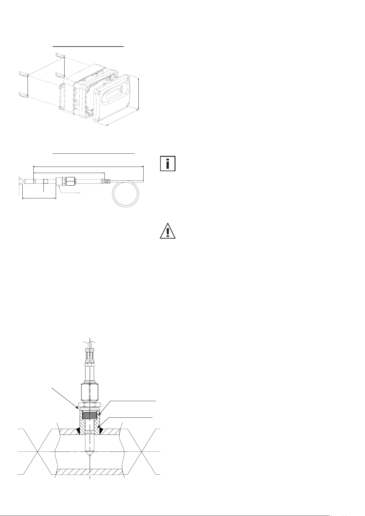
3.3 Model E (remote sensing probe, pressure tight up to 20bar (300psi))
Mounting of transmitter:
1. Drill the mounting holes according to the mounting template (see
drawing at the beginning of the chapter "Drilling/Mounting Template") .
2. The bottom part of the housing is mounted with 4
screws (screw diameter: < 4.2mm (0.2”) ; not included
in the scope of supply).
135
Mounting of sensing probe:
code “cable length”
code “probe length”
(3.5”)
90
(5.3”)
3. Connection of the transmitter (see Hardware,
chapter 4 "Electrical connections").
4. Mounting of the middle part and cover with 4 screws
(included in the scope of supply).
The sensing probe must be mounted horizontally or
vertically, pointing downwards. When possible, a drip sheet
should be fitted for each mounting.
∅13 (0.51”)
adjustable
min. 23 / max. 44/164/364
∅12
1/2” ISO or 1/2” NPT
(0.47”)
fixed installation
(pressure tight up
to 20bar
(300psi))
Working range sensing probe: -40...180°C
(-40...356°F)
Pressure range model: 0.01...20bar (0.15...300psi)
General safety instructions for installation
Because the sensing probe can be exposed to very high
pressures in the measurement environment, there is the risk
of sudden, unintentional expulsion of the probe during or
after improper installation. Therefore, special precautions
should be taken when working on the sensing probe or in its
vicinity. Bending over the sensing probe should be avoided
underany circumstances!
During the installation of the sensor probe, make sure that
the surface of the sensing probe is not damaged! Damaging
the probe could lead to damaged seals (consequence: leakage
and pressure loss) and to problems during removal (jamming).
Installation of the probe directly in the process
For direct probe installation, a stop valve should be provided on
both sides of the probe insert. This allows the sensor probe to be
removed for maintenance and calibration without any problems.
metal sealing ring
1/2” ISO or 1/2“ NPT
inside diameter
≥ 13 mm (0.55”)
stop valve stop valve
If the sensor probe is installed in a pressure chamber, make
sure that the pressure in the chamber and the ambient pressure are in equilibrium before you remove the probe.
The temperature during installation may not vary more than
±4°C (±72°F) from the operating temperature.
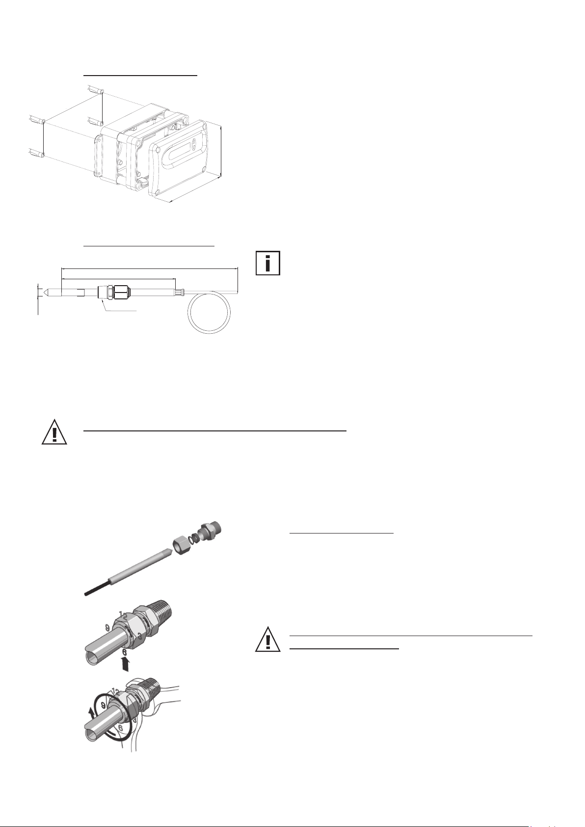
1st step:
Install the probe with the stop valves closed.
2nd step:
Insert the sensor probe into the process.
3rd step:
To ensure a secure installation of the probe, the lock nut must
be tightened to a defined torque of 30 Nm.
If no torque-spanner is available tighten the lock nut by hand
as far as possible. Continue to turn with an open-ended
spanner ~50°.
Hardware
9
Page 10
3.4 Model I (remote sensing probe, pressure tight up to 100bar (1450psi))
Mounting of transmitter:
1. Drill the mounting holes according to the mounting template (see
drawing at the beginning of the chapter "Drilling/Mounting Template") .
2. The bottom part of the housing is mounted with 4
screws (screw diameter: < 4.2mm (0.2”) ; not included
in the scope of supply).
135
(3.5”)
90
(5.3”)
3. Connection of the transmitter (see Hardware,
chapter 4 "Electrical connections").
4. Mounting of the middle part and cover with 4 screws
(included in the scope of supply).
Mounting of sensing probe:
The sensing probe must be mounted horizontally or
code “cable length”
code “probe length”
vertically, pointing downwards. When possible, a drip sheet
should be fitted for each mounting.
∅12
(0.5”)
1/2” ISO or
1/2” NPT
Working range sensing probe: -40...180°C
Pressure range model I: 0...100bar (0...1450psi)
Safety Precautions for pressure tight screw connection
- Do not bleed system by loosening fitting nut or fitting plug.
- Do not make up and tighten fittings when system is pressurized.
- Always use proper thread sealants on tapered pipe threads.
- Never turn fitting body. Instead, hold fitting body and turn nut.
- Avoid unnecessary disassembly of unused fittings.
Installation instruction
Rotate the nut finger-tight.
Mark the nut at the 6 o'clock position.
While holding the fitting body steady, tighten the nut one and
one-quarter turns to the 9 o'clock position.
(-40...356°F)
Hardware
Installation in High-Pressure Applications and High
Safety-Factor Systems
1. Rotate the nut finger-tight.
2. Tighten the nut until the tuwbing will not turn by hand or
move axially in the fitting.
3. Mark the nut at the 6 o'clock position.
4. While holding fitting body steady, tighten the nut one and
one-quarter turns to the 9 o'clock position.
10
Page 11
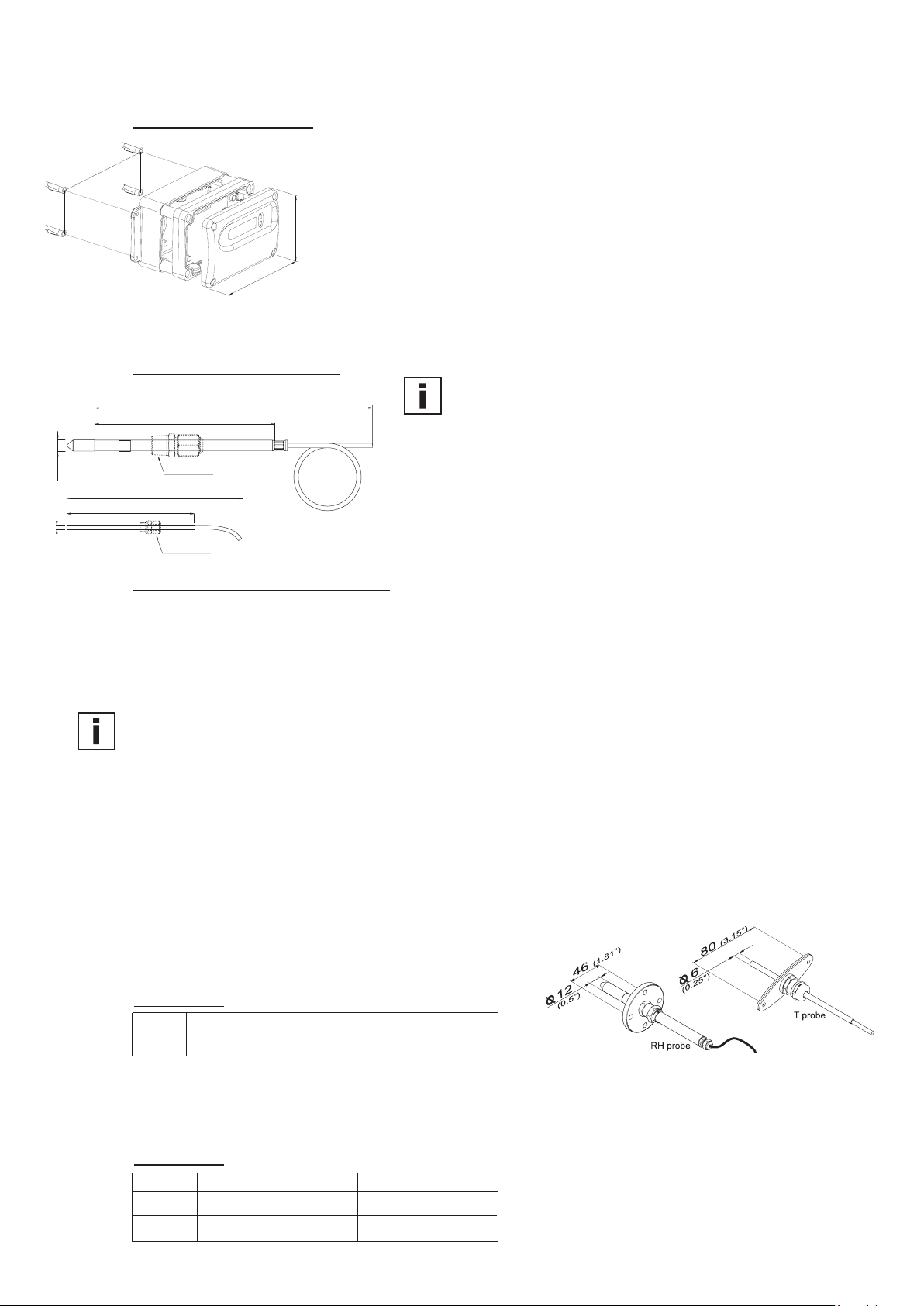
3.5 Model J (2 remote sensing probes, pressure tight up to 20bar (300psi))
Mounting of transmitter:
1. Drill the mounting holes according to the mounting template (see
drawing at the beginning of the chapter "Drilling/Mounting Template") .
2. The bottom part of the housing is mounted with 4
screws (screw diameter: < 4.2mm (0.2”) ; not included
(3.5”)
90
(5.3”)
135
Mounting of sensing probe:
The sensing probe must be mounted horizontally or
code “probe length”
code “cable length”
in the scope of supply).
3. Connection of the transmitter (see Hardware,
chapter 4 "Electrical connections").
4. Mounting of the middle part and cover with 4 screws
(included in the scope of supply).
vertically, pointing downwards. When possible, a drip sheet
should be fitted for each mounting.
∅12
∅6
(0.5”)
code “cable length”
150 (5.9”)
(0.25”)
1/2” ISO or 1/2” NPT
Mounting the two probes, please make sure that the
minimum distance is 10cm (4").
(-40...356°F)
1/2” ISO or 1/2” NPT
Working range sensing probe: -40...180°C
Pressure range: 0.01...20bar (0.15...300psi)
Pressure tight screw connections: The screw connections for pressure tight installation up to 20bar
(300psi) are available as accessories (see Hardware chapter 10.
“Replacement Parts/Acceccories”). For screw assembly refer
to Hardware chapter 3.5 “Model E (remote sensing probe,
pressure tight up to 20bar (300psi))”.
Instructions for installation in a high-humidity environment:
If the process temperature differs significantly from the ambient temperature, the sensing probe should be
fully emerged in the process to avoid incorrect measurements and condensation problems on the sensor
head due to thermal conductivity.
It is recommended not to bring the sensing probe and colder metal parts in direct contact in order to avoid
condensation problems caused by thermal conductivity.
The humidity probe (12mm (1/2")) and the temperature probe (6mm (1/4")) must be mounted at the same
temperature level respectivily same installation height.
Mounting of sensing probe with flange (accessories):
A mounting flange 12mm (1/2”) for the humidity probe and a
mounting flange 6mm (1/4") for for the temperature probe
are available as accessories.
Order codes:
RH probe (12mm (1/2")) T probe (6mm (1/4"))
flange HA010201 HA010207
Mounting of sensing probe with screw connection (accessories):
A 1/2” ISO resp. a 1/2” NPT screw connection is available as an accessories for mounting both sensing
probes (6mm (1/4") and 12mm (1/2")).
Order codes:
RH probe (12mm (1/2")) T probe (6mm (1/4"))
1/2” ISO HA011102 HA011104
1/2” NPT HA011103 HA011105
11
Hardware
Page 12
3.6 Model K (remote sensing probe, pressure tight up to 15bar (218psi))
Mounting of transmitter:
1. Drill the mounting holes according to the mounting template (see
drawing at the beginning of the chapter "Drilling/Mounting Template") .
2. The bottom part of the housing is mounted with 4
screws (screw diameter: < 4.2mm (0.2”) ; not included
(3.5”)
90
(5.3”)
135
Mounting of sensing probe:
in the scope of supply).
3. Connection of the transmitter (see Hardware,
chapter 4 "Electrical connections").
4. Mounting of the middle part and cover with 4 screws
(included in the scope of supply).
Using the stainless steel mounting flange (refer to accessories)
it is possible to mount the probe on the outer wall of the
measuring chamber.
The depth of immersion is adjustable.
For roof installations use the drip water protection (refer to
accessories) to protect the sensor head and elements against
condensed water.
The sensing probe must be mounted horizontally or vertically,
pointing downwards. When possible, a drip sheet should be
fitted for each mounting.
Working range of sensing probe: -40...180°C
(-40...356°F)
Pressure range: 0.01...20bar (0.15...300psi)
Pressure tight screw connection: The screw connection for pressure tight installation up to 15bar
(218psi) is available as an accessory (see Hardware chapter 10.
“Replacement Parts/Acceccories”). For screw assembly refer
to Hardware chapter 3.5 “Model E (remote sensing probe,
pressure tight up to 20bar (300psi))”.
Instructions for installation in a high-humidity environment:
If the process temperature differs significantly from the ambient temperature, the sensing probe should be
fully emerged in the process to avoid incorrect measurements and condensation problems on the sensor
head due to thermal conductivity.
It is recommended not to bring the sensing probe and colder metal parts in direct contact in order to avoid
condensation problems caused by thermal conductivity.
Mounting of sensing probe with flange (accessories):
A 12mm
(1/2”) mounting flange (HA010201) for the humidity probe is available as an accessories.
Mounting of sensing probe with screw connection (accessories):
A 1/2" ISO (HA011102) and 1/2" NPT (HA011103) screw connection for the sensing probe is available as an
accessories.
Hardware
12
Page 13
4. ELECTRICAL CONNECTIONS
1
2
3
4
5
1
2
3
4
5
1
2
3
4
5
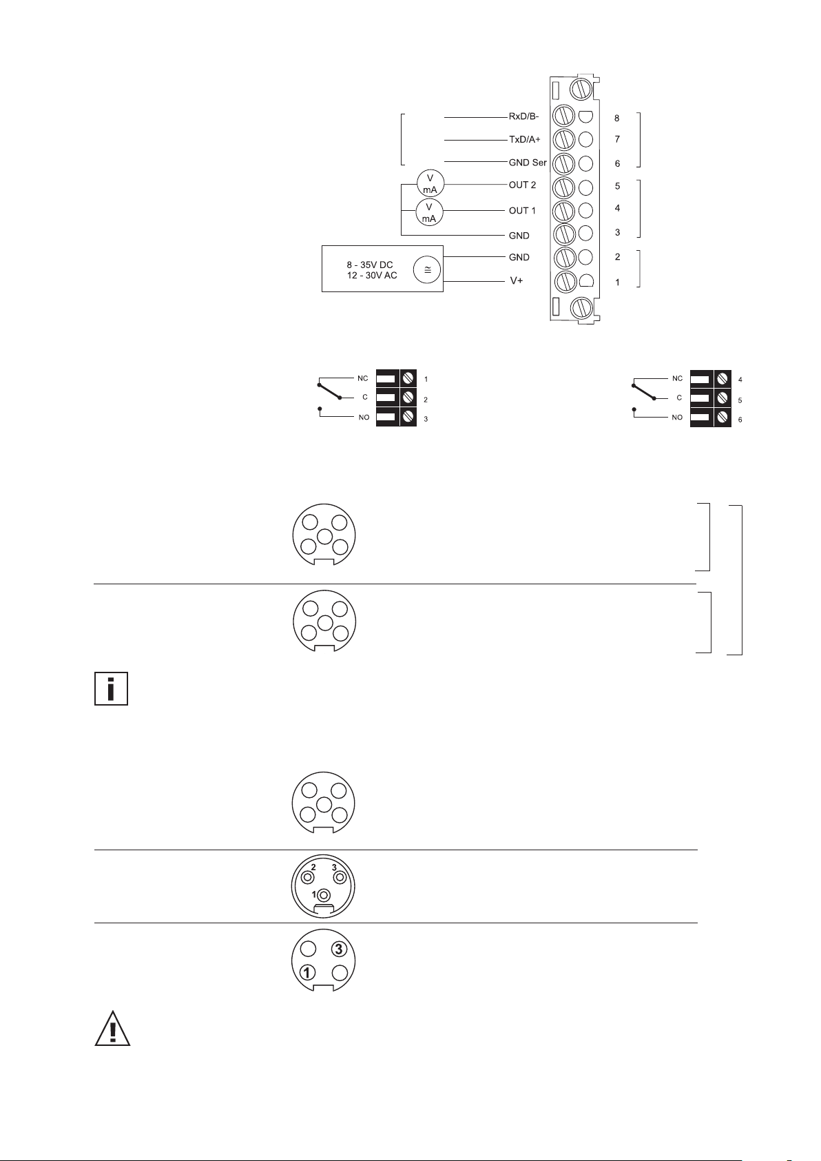
4.1 Connection diagram
RS232 / RS485
cable
white
brown
yellow
serial data
output
analogue
output
supply
4.2 Alarm module connection diagram (option)
Rel 1
Rel 2
4.3 Connection configuration of bottom part of the housing with plug connections /
8...35V DC; 12...30V AC (option C03/C06/C07/C08)
Description: Connection assignment:
Plug for supply and
analogue output
(front view)
Euro-Standard
Plug for RS232 resp.
RS484 connection
(front view)
Euro-Standard
V+ 5
GND 4
GND 3
OUT1 2
OUT2 1
Description: Connection assignment:
GND-Ser 5
Rxd/B- 3
Txd/A+ 1
not assigned 2, 4
C03
C06
C07
C08
The cable should be connected according to the number stamped in the plug as shown in the above drawings!
4.4 Connection configuration of bottom part of the housing with integrated power supply /
100...240V AC (option V01)
Description: Connection assignment:
Plug for RS232 and
analogue output
(front view)
Euro-Standard
Plug for 100-240V
metal housing
(front view)
Plug for 100-240V
polycarbonate housing
(front view)
External diameter of supply cable: 10-12mm (0.39-0.47”)
Maximum wire cross section for connecting cable: 1.5mm² (AWG 16)
The protection of the supply cable against excess current and short-circuit must be designated
to a wire cross section of 0.8mm² (AWG 18) (6A fuse).
National regulations for installation must be observed!
RxD / B- 5
TxD / A+ 4
GND 3
OUT1 2
OUT2 1
Description: Connection assignment:
grounding (PE) 1
phase (L1) 2
neutral wire (N) 3
Description: Connection assignment:
phase (L1) 1
neutral wire (N) 3
Bottom and middle part of the metal housing must be grounded during operation!
13
Hardware
Page 14
4.5 Connection configuration of connectable sensing probe (option P03)
3 12
4
6
5
8
9
7
3 1
2
4
6
5
8
7
Rosa
Schwarz
Blau
Gelb
Braun
Grau
Schirm
Gelb/Grau
Schirm
12mm (0.5”) sensing probe:
grey
shielding
shielding (yellow/green)
9-pole terminal
(0.25”) sensing probe:
6mm
shielding
5-pole terminal
blue
grey (yellow/green)
grey
brown
yellow
black
brown
blue
black
pink
5. OPERATING COMPONENTS
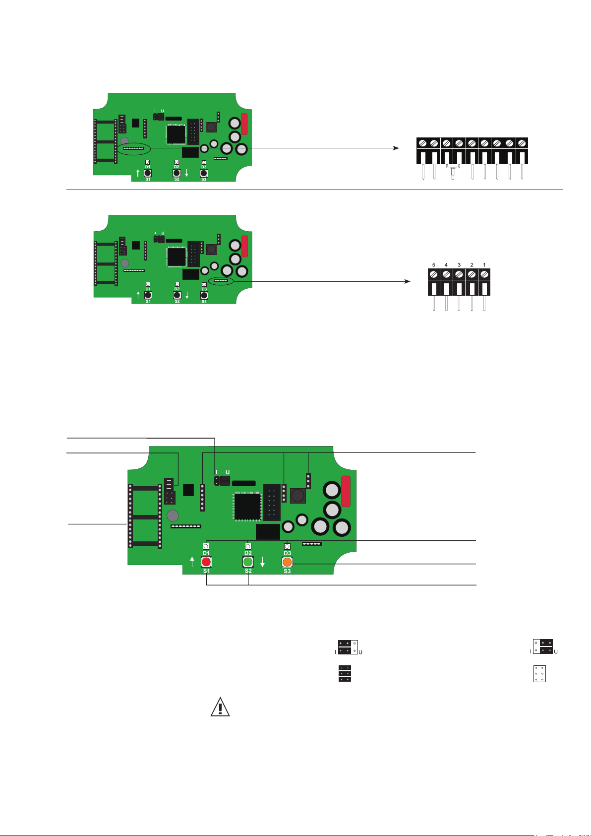
5.1 Circuit board
After removal the housing cover, the following operating components on the circuit board may be accessed.
1. current/voltage output
2. RS232/RS485
3. fitting of the
network chip
1. Current/voltage output: If the transmitter will be switched from current to voltage output signals
using the configuration software supplied, then two jumpers must also be
positioned as follows:
for current signal: for voltage signal:
4. display
5. diagnosis LEDS
6. push-button (heated measurement cell)
7. push-buttons (calibration)
Hardware
2. RS232/RS485: jumper set - RS232: jumper removed - RS485:
3. Fitting of the network chip: For refitting to RS485, an IC must be used (available as an option).
The notch on the chip must match the receiver slot!
4. Display: Pinboards for connecting the display module.
5. Diagnosis LEDS: refer to Hardware, chapter 7 “Humidity/Temperature Calibration”
refer to Hardware, chapter 8.4 “Self-diagnosis and error messages”
6. Push-button (heated measurement cell): refer to Hardware, chapter 8.2 “Automatic ReCover (ARC)”
7. Push-buttons (calibration): refer to Hardware, chapter 7 “Humidity/Temperature Calibration”
14
Page 15
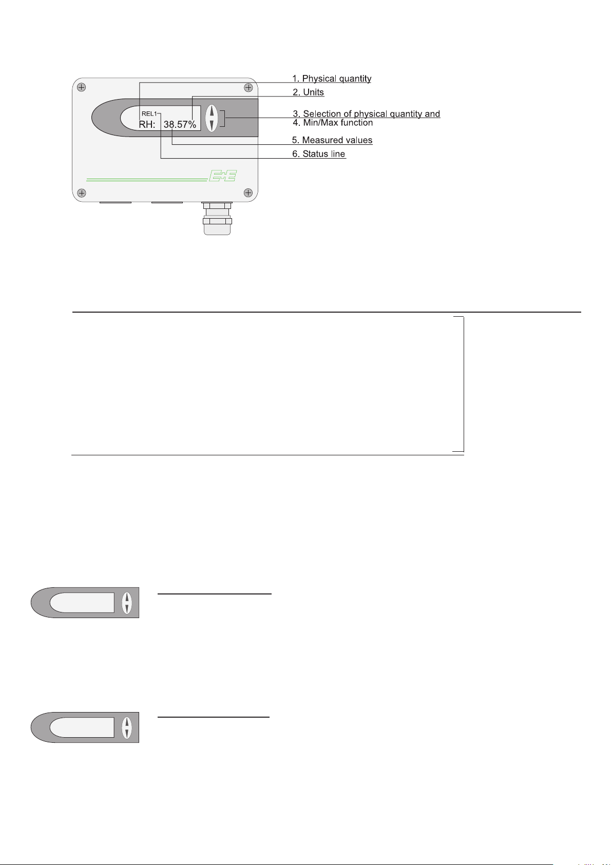
5.2 Display module (Option)
RH: 63.0%
MAX
RH: 63.0%
MIN
1. PHYSICAL QUANTITY:
2. UNITS:
3. SELECTION OF PHYSICAL QUANTITY:
SI US
RH Rel. humidity % %
T Temperature °C °F
e Water vapour partial pressure mbar psi
Td Dew point temperature °C °F
Tw Wet bulb temperature °C °F
EE33
Press the ∆ or ∇
button to select the
desired physical
quantity.
dv Absolute humidity g/m³ gr/ft³
r Mixture ratio g/kg gr/lb
h Enthalphy kJ/kg ftlbf/lb
Tf Frost point temperature °C °F
4. MIN / MAX FUNCTION:
The MIN / MAX function saves and displays the highest and lowest measured value since the last reset resp. the
last interruption of the supply voltage.
Highest measured value:
1. Select the desired physical quantity.
2. To display the maximum value of the selected physical quantity, press the ∆ button for
at least five seconds.
3.1. To reset the transmitter to its normal operating status, press the ∆ button once again
for five seconds.
3.2. If both buttons are pressed for at least five seconds while the maximum value is displayed
→ the "MAX" symbol disappears → the maximum value will be deleted (Reset).
Lowest measured value:
1. Select the desired physical quantity.
2. To display the minimum value of the selected physical quantity, press the ∇ button for
at least five seconds.
3.1. To reset the transmitter to its normal operating status, press the ∇ button once again
for five seconds.
3.2. If both buttons are pressed for at least five seconds while the minimum value is displayed →
the "MIN" symbol disappears → the minimum value will be deleted (Reset).
Hardware
15
Page 16

5. MEASURED VALUES / MAX. MEASUREMENT RANGE:
The dominant value of the appropriate quantity is displayed in this field. For the factory configuration, the
measured values may fall between the measurement ranges shown below.
EE33-C EE33-D/E/I/J EE33-K
Humidity RH 0 100 100 / % rF
Temperature T -40
Dew point temperature Td -40 (-40) 100 (212) 100 (212) 100 (212) °C (°F)
Frost point temperature Tf -40 (-40) 0 (32) 0 (32) 0 (32) °C (°F)
Wet bulb temperature Tw 0 (32) 100 (212) 100 (212) / °C (°F)
Water vapour partial pressure e 0 (0) 1100(15) 1100 (15) / mbar (psi)
Mixture ratio r 0 (0) 999 (9999) 999 (9999) / g/kg (gr/lb)
Absolute humidity dv 0 (0) 700 (300) 700 (300) / g/m
Specific enthalpy h 0 (0) 2800 (999999) 2800 (999999) / kJ/kg (Btu/lb)
The measurement ranges indicated above can be set to individual requirements using the configuration software supplied
(see Configuration software, chapter 5 "Index - Index Cards").
from to unit
(-40) 120 (248) 180 (356) / °C (°F
3
(gr/f³)
6. STATUS LINE:
MIN; MAX: see Point "MIN/MAX Function", see Hardware, chapter 5.2 “Display module”
CALIB LOW; CALIB HIGH: indicates the low or high humidity/temperature calibration point.
REL1 / REL2: status relay 1/ relay 2
"ERROR 01....06": see Hardware, chapter 8.4 “Self-diagnosis and error messages”
EE33
6. OPTIONAL MODULES
The optional modules are mounted in the lower part, that's why always only one optional module can be selected.
6.1 Alarm Module (Option)
The optional alarm module can be used for alarm and error issues and other simple control functions. This
module can be configured using the configuration software supplied.
The user thus has the option of setting the physical quantity to be monitored (RH, T, Td,...) and the threshold and
hysteresis for each relay. (For the procedure, see the Configuration sofware, chapter 5.2 “Relay”)
Max. switched voltage / max. switched current: 250 VAC / 6A
28 VDC / 6A
Minimum load: >100mA / 12V
Switching relay 1:
REL1
RH: 63.0%
If relay 1 has tripped (ON),
then REL1 is displayed.
EIN
ON
AUS
OFF
Ausschaltpunkt
switching off
relay status
11
12
13
11
12
13
Relais Status
NC
C
NO
NC
C
NO
Hysterese
8%
Einschaltpunkt
switching on
62
70
Schaltpunkt
switching point
[%,°C,kj/kg,
g/kg,g/m³,mbar,...]
Switching relay 2:
Hardware
REL2
RH: 63.0%
If relay 2 has tripped (ON),
then REL2 is displayed.
16
EIN
ON
AUS
OFF
Ausschaltpunkt
switching off
relay status
14
15
16
14
15
16
Relais Status
NC
C
NO
NC
C
NO
Hysterese
8%
Einschaltpunkt
switching on
62
70
Schaltpunkt
switching point
[%,°C,kj/kg,
g/kg,g/m³,mbar,...]
Page 17

6.2 Integrated Power Supply (Option)
see Hardware, chapter 4.4 Connection configuration of bottom part of the housing with integrated power
supply 100...240V AC (option V01)
6.3 Ethernet Module (Option)
6.4 ARC-Module (Option)
see Hardware, chapter 9.2 Ethernet - Module (Option)
The additional printed circuit board located in the lower part of the
housing offers the possibiliy to start the ARC heating function with
external signal.
During the heating process the orange LED D3 flashes at the main
printed circuit board. At the ARC-Module the red LED "heating" flashes
and the relay contact (terminal "output") is closed.
General information of the ARC function see Hardware, chapter 2.1.1
Automatic ReCover (ARC).
For changes of the parameter of the heating process, see Software,
chapter 5.5 Parameter.
6.4.1 Connection / Operating elements
Terminal „+Ub“:
supply voltage: 24V AC/DC +/-20%
1 GND
2 +Ub
Terminal „Input“:
1 GND
2 signal (24V DC; 10mA)
Terminal „Output“:
1 REL_com
2 Rel_NO
Feedback signal to the external control.
The relay contact is closed during the heating
process, otherwise opened.
Timing of switching status
Operating elements:
- LED green: LED ashes = supply voltage is switched on
- LED red: LED ashes = heating process is active
Hardware
17
Page 18

7. HUMIDITY / TEMPERATURE CALIBRATION
The EE33 transmitter series can be calibrated in two ways:
- 1-point humidity/temperature calibration: quick and simple calibration on a defined humidity/temperature
point (working point).
- 2-point humidity/temperature calibration: calibration for accurate measuring results over the whole
humidity/temperature working range.
• To reach a temperature balance it is recommended to keep the transmitter and the
reference chamber (e.g. HUMOR 20,...) for minimum 4 hours in the same room.
• During stabilisation period and calibration procedure it is important to keep the temperature constant
in the reference climate chamber.
• For calibration the humidity sensor probe must be stabilised at least 20 minutes into the reference chamber.
• Replace an used dirty filter cap before calibration!
7.1 2-point humidity calibration
For accurate adjustment over the whole humidity working range a 2-point calibration is recommended.
• Start calibration at the low humidity calibration point!
• The humidity difference between the two points should be > 30%RH
• Low humidity point < high humidity point
• 2-point calibration may be performed directly on the circuit board, or using the configuration software
supplied (for more details, see Configuration Software, chapter 5.4 ”2-point humidity calibration”)
low calibration point:
“CALIB LOW”
2-point humidity calibration procedure on the circuit board:
1. Insert the sensor probe into the reference humidity 1 (low
calibration point) and stabilise for at least 20 minutes.
2. BUTTON S2: Pressing the button for 5 seconds starts the
procedure for the calibration mode RH. The calibration mode is
indicated by the lit LED "D2" on the circuit board.
3. BUTTON S2: Pressing the button for 5 seconds starts the
procedure for the low calibration point. The calibration mode is
indicated by the lit LED "D2" and the symbol "CALIB LOW" will
appear on the optional LC display.
4. BUTTON S1 (up) and S2 (down): Pressing one of the two
buttons will adjust the measuring value in steps of 0.1% up or
down to the reference value. The actual measuring value is
indicated on the display or can be measured with the analogue
output. As soon as the measured value is changed, "D1"
flashes when pressing S1 or S2.
Hardware
5. BUTTON S1 (store): Pressing the button for 5 seconds
stores the calibration value and the procedure is ended. LED
"D2" flashes to indicate exiting of the calibration mode and the
symbol "CALIB LOW" will disappear from the optional
LC display.
BUTTON S2 (cancel): Pressing the button for 5 seconds the
calibration procedure will be ended without storing the
calibration values. LED "D2" flashes to indicate exiting of the
calibration mode and the symbol "CALIB LOW" will
disappear from the optional LC display.
18
Page 19

high calibration point:
“CALIB HIGH”
6. Insert the sensor probe into the reference humidity 2 (high
calibration point) and stabilise for at least 20 minutes.
7. BUTTON S2: Pressing the button for 5 seconds starts the
procedure for the calibration mode RH. The calibration mode is
indicated by the lit LED "D2" on the circuit board.
8. BUTTON S1: Pressing the button for 5 seconds starts the
procedure for the high calibration point. The calibration mode is
indicated by the lit LED "D2" and the symbol "CALIB HIGH" will
appear on the optional LC display.
9. BUTTON S1 (up) and S2 (down): Pressing one of the two
buttons will adjust the measuring value in steps of 0.1% up or
down to the reference value. The actual measuring value is
indicated on the display or can be measured with the analogue
output. As soon as the measured value is changed, "D1"
flashes when pressing S1 or S2.
10. BUTTON S1 (store): Pressing the button for 5 seconds
stores the calibration value and the procedure is ended. LED
"D2" flashes to indicate exiting of the calibration mode and the
symbol "CALIB HIGH" will disappear from the optional LC display.
BUTTON S2 (cancel): Pressing the button for 5 seconds the
calibration procedure will be ended without storing the
calibration values. LED "D2" flashes to indicate exiting of the
calibration mode and the symbol "CALIB HIGH" will disappear
from the optional LC display.
7.2 2-point temperature calibration
•
Start calibration at the low calibration point!
• The temperature difference between the two points should be at least 30°C (86°F)!
• Low temperature point < high temperature point
• Attention: A 2-point temperature calibration is not supported by the
configuration software and must therefore be done directly on the circuit
board! (see following page)
19
Hardware
Page 20

2-point temperature calibration procedure on the circuit board:
low calibration point:
“CALIB LOW”
1. Insert the sensor probe into the reference temperature 1 (low
calibration point) and stabilise for at least 10 minutes.
2. BUTTON S1: Pressing the button for 5 seconds starts the
procedure for the calibration mode temperature. The calibration
mode is indicated by the lit LED "D1" on the circuit board.
3. BUTTON S2: Pressing the button for 5 seconds starts the
procedure for the low calibration point. The calibration mode is
indicated by the symbol "CALIB LOW" on the optional LC display.
4. BUTTON S1 (up) and S2 (down): Pressing one of the two
buttons will adjust the measuring value in steps of 0.1 degC up
or down to the reference value. The actual measuring value is
indicated on the display or can be measured with the analogue
output. As soon as the measured value is changed, "D1"
flashes when pressing S1 or S2.
5. BUTTON S1 (store): Pressing the button for 5 seconds
stores the calibration value and the procedure is ended. LED
"D2" flashes to indicate exiting of the calibration mode and the
symbol "CALIB LOW" will disappear from the optional LC display.
BUTTON S2 (cancel): Pressing the button for 5 seconds the
calibration procedure will be ended without storing the
calibration values. LED "D2" flashes to indicate exiting of the
calibration mode and the symbol "CALIB LOW" will disappear
from the optional LC display.
high calibration point:
Hardware
“CALIB HIGH”
6. Insert the sensor probe into the reference temperature 2
(high calibration point) and stabilise for at least 10 minutes.
7. BUTTON S1: Pressing the button for 5 seconds starts the
procedure for the calibration mode temperature. The calibration mode is indicated by the lit LED "D1" on the circuit board.
8. BUTTON S1: Pressing the button for 5 seconds starts the
procedure for the high calibration point. The calibration mode
is indicated by the symbol "CALIB HIGH" on the optional LC
display.
9. BUTTON S1 (up) and S2 (down): Pressing one of the two
buttons will adjust the measuring value in steps of 0.1°C up or
down to the reference value. The actual measuring value is
indicated on the display or can be measured with the analogue
output. As soon as the measured value is changed, "D1"
flashes when pressing S1 or S2.
10. BUTTON S1 (store): Pressing the button for 5 seconds
stores the calibration value and the procedure is ended. LED
"D2" flashes to indicate exiting of the calibration mode and the
symbol "CALIB HIGH" will disappear from the optional LC
display.
BUTTON S2 (cancel): Pressing the button for 5 seconds the
calibration procedure will be ended without storing the
calibration values. LED "D2" flashes to indicate exiting of the
calibration mode and the symbol "CALIB HIGH" will
disappear from the optional LC display.
20
Page 21

7.3 1-point humidity calibration
When the working range is limited to a certain more narrow range,
a calibration at one humidity point is absolutely sufficient.
• In accordance with the working range, either the high or low
calibration point should be selected. (CP > or < 50% RH)
• This calibration causes an extra inaccuracy for the rest of the
working range.
• The 1-point humidity calibration may be done directly on the
circuit board, or for convenience, using the configuration software supplied. (for more details, see Configuration software,
chapter 5.4 “Calibration” / 1-point humidity calibration)
1-point humidity calibration procedure on the circuit board:
1. Insert the sensor probe into the reference humidity
(calibration point) and stabilise for at least 20 minutes.
“CALIB HIGH”
“CALIB LOW”
2. BUTTON S2: Pressing the button for 5 seconds starts the
procedure for the calibration mode RH. The calibration mode is
indicated by the lit LED "D2" on the circuit board.
3. BUTTON S1: Pressing the button for 5 seconds starts the
procedure. The calibration mode is indicated by the lit LED
"D2" and the symbol "CALIB HIGH" will appear on the optional
LC display (CP ≥ 50% RH).
or
BUTTON S2: Pressing the button for 5 seconds starts the
procedure. The calibration mode is indicated by the lit LED
"D2" and the symbol "CALIB LOW" will appear on the optional
LCD (CP < 50% RH).
4. BUTTON S1 (up) and S2 (down): Pressing one of the two
buttons will adjust the measuring value in steps of 0.1% up or
down to the reference value. The actual measuring value is
indicated on the display or can be measured with the analogue
output.
5. BUTTON S1 (store): Pressing the button for 5 seconds
stores the calibration value and the procedure is ended. LED
"D2" flashes to indicate exiting of the calibration mode and the
symbol "CALIB LOW" or "CALIB HIGH" will disappear from the
optional LC display.
BUTTON S2 (cancel): Pressing the button for 5 seconds the
calibration procedure will be ended without storing the
calibration values. LED "D2" flashes to indicate exiting of the
calibration mode and the symbol "CALIB LOW" or "CALIB
HIGH" will disappear from the optional LC display.
Hardware
21
Page 22

7.4 1-point temperature calibration
When the working range is limited to a certain more narrow range,
a calibration at one temperature point is absolutely sufficient.
• In accordance with the working range, either the high or low
calibration point should be selected. (CP ≥ or < 45 degC / 113°F)
• This calibration causes an extra inaccuracy for the rest of the
working range.
• The 1-point temperature calibration may be performed directly
on the circuit board, or using the configuration software supplied.
(for more details, see Calibration software, chapter
5.4 “Calibration” / 1-point humidity calibration)
1-point temperature calibration procedure on the circuit board:
1. Insert the sensor probe into the reference temperature
(calibration point) and stabilise for at least 30 minutes.
“CALIB HIGH”
“CALIB LOW”
2. BUTTON S1: Pressing the button for 5 seconds starts the
procedure for the calibration mode temperature. The calibration
mode is indicated by the lit LED "D1" on the circuit board
3. BUTTON S1: Pressing the button for 5 seconds starts the
procedure. The calibration mode is indicated by the symbol
"CALIB HIGH" on the optional LC display (CP ≥ 45°C /
or
BUTTON S2: Pressing the button for 5 seconds starts the pro-
cedure. The calibration mode is indicated by the symbol "CALIB
LOW" on the optional LC display (CP < 45°C / 113°F).
4. BUTTON S1 (up) and S2 (down): Pressing one of the two
buttons will adjust the measuring value in steps of 0.1°C up or
down to the reference value. The actual measuring value is
indicated on the display or can be measured with the analogue
output.
5. BUTTON S1 (store): Pressing the button for 5 seconds
stores the calibration value and the procedure is ended. LED
"D2" flashes to indicate exiting of the calibration mode and the
symbol "CALIB LOW" or "CALIB HIGH" will disappear from the
optional LC display.
BUTTON S2 (cancel): Pressing the button for 5 seconds the
calibration procedure will be ended without storing the
calibration values. LED "D2" flashes to indicate exiting of the
calibration mode and the symbol "CALIB LOW" or "CALIB
HIGH" will disappear from the optional LC display.
113°F).
Hardware
22
Page 23

7.5 Resetting the customer calibration to the
factory calibration on the circuit board:
1. RH + T RESET: BUTTON S1 and S2: In neutral mode
pressing both buttons simultaneously for 10 seconds customer
calibration settings are reset to factory calibration.
A short flash of the LED "D1" indicates the reset.
or
2. RH RESET: BUTTON S2: Pressing the button for 5
seconds starts the procedure for the calibration mode RH.
Pressing both buttons simultanously for 10 seconds customer
calibration settings are reset to factory calibration.
A short flash of the LED "D1" indicates the reset.
or
3. Temp. RESET: BUTTON S1: Pressing the button for 5
seconds starts the procedure for the calibration mode T.
Pressing both buttons simultanously for 10 seconds customer
calibration settings are reset to factory calibration.
A short flash of the LED "D2" indicates the reset.
23
Hardware
Page 24

7.6 Adjustment/Calibration EE33 model J
7.6.1 Adjustment/Calibration with humidity calibrator HUMOR 20
To be able to calibrate the transmitter of the series EE33-MFTJ, with the dual
probes (Td-probe and T–probe), a separate available adapter is needed (siehe
Hardware, chapter 10. replacement parts/accessories - adapter for EE33 - model J,
HA020401) to achieve the highest possible calibration result. The following steps
describe how the series EE33-MFTJ should be calibrated correctly.
1. Plug both air vents of the cover of the measurement chamber with the plugs
supplied with the adapter (see left picture).
2. Insert the Td-probe (Ø12mm) in the measuring chamber through one of the
feed-throughs of the cover and tighten the nut.
3. Insert and tighten the T-probe (Ø6mm) in the adapter and insert in the
measuring chamber through one of the feed-throughs of the cover and
tighten the nut.
4. In case that feed-throughs are not in use, close them with the blind plugs
delivered with the cover.
Transmitters delivered after June 2009 have the possibility to heat the tube
of the probe continuously to avoid condensation. This function must be
disabled prior to calibration, by detaching the cover of the transmitter and
removing the “heat”-jumper in the left top corner of the PCB
(see left picture).
5. Connect the test unit to the supply connections of HUMOR 20.
6. Connect the output signal of the test unit(s) to the internal measuring
inputs of HUMOR 20 (Unit1 RH, Unit2 RH).
7. Select the measuring ranges in accordance with the output signal of the test units.
The temperature of the measuring chamber can be displayed by selecting
"Temp." on the measuring range switch.
8. Use the humidity controller to select the setpoint of the humidity.
9. For information on the standard deviations and stabilisation times of the
test unit, refer to the manufacturer's documentation (however, a minimum
of 20 mins is recommended).
10. Compare the values shown in the display with the output signal of the
transmitter.
Hardware
After calibration, make sure that the plugs in the air vents in the cover of the
measuring chamber are removed.
7.6.2 Adjustment/Calibration with various calibrators
For an exact calibration, note especially point 4 in the above chapter.
24
Page 25

8. MAINTENANCE
8.1 Sensor cleaning
It is easy to clean the sensor if there are particle deposits (e.g. dust) on the surface of the
heated measurement cell.
Commercially available isopropyl alcohol is used for cleaning. Unscrew the filter cap and
submerge the sensor element in the alcohol for 2 minutes.
Allow the sensor element to dry or blow it dry with oil-free compressed air.
Caution: In order to avoid destroying the active sensor coating, avoid using mechanical
aids (e.g. cotton swabs or cloths) for cleaning!
8.2 Automatic ReCover (ARC)
When capacitive humidity sensors are exposed to chemical pollution (e.g. detergent
residue), the presence of foreign molecules can distort the measurement reading.
The foreign molecules can be evaporated by heating the measurement cell briefly and
intensively. Reconditioning helps to minimize distorted measurement readings during the
calibration interval.
It is recommended to heat the measurement cell by choosing Manual after the cleaning or
sterilization process or if distorted measurement readings are suspected.
To start heating, remove the housing cover and press the pushbutton S3 or trigger the
ARC-module with the external signal (see Hardware, chapter 6.4 ARC-Module).
The orange LED D3 is illuminated during heating.
8.3 Fuse replacement for option V01
If the green LED on the PCB is not flashing with the supply
voltage switched on, check the fuse and replace if required.
Fuse secondary: 250mA / T UL248-14
Nominal voltage: 250V
Replacement types:
Series: MSTU 250 Manufacturer: Schurter Order No.: 0034.7109
Series: 374 Manufacturer: Littelfuse Order No.: 374 0250
25
Hardware
Page 26

8.4 Self diagnosis and error messages
Self diagnosis via LEDs on the circuit board:
• LED D2 (green)
Flashing
⇒ Supply voltage applied / Microprocessor is active
• LED D1 (red)
Constantly lit
Flashing
⇒ Humidity sensor element damaged
⇒ Dew (condensation) at the humidity sensor element
• LED D3 (orange)
Constantly lit ⇒ Humidity sensor element will be heated (Automatic ReCover)
Flashing ⇒ Sensor and threaded element soiled
Self diagnosis via display (optional):
Error 1 ⇒ Humidity sensor element damaged
Error 2 ⇒ Humidity sensor element moistened (condensation!)
Error 3 ⇒ Temperature sensor element damaged
Error 4 ⇒ Temperature sensor short-circuit
Error 5 ⇒ Pt1000-probe element is damaged
Error 6 ⇒ Pt1000-probe short-circuit
EE33-MFTJ
Further self diagnosis:
• Error
Possible cause
⇒ Measures / Help
• Display shows incorrect values
Error during re-adjustment of the transmitter
⇒ Reset to factory calibration and repeat the calibration routine
Filter soiled
⇒ Replace filter
Measuring cell contaminated
⇒ Automatic ReCover (ARC)
Output configured incorrectly
⇒ Check output range and output signals in the configuration
• Long response time
Filter soiled
⇒ Replace filter
Incorrect filter type
⇒ Filter type should match the application
Hardware
• Transmitter failure
No supply voltage
⇒ Check wiring and supply voltage
⇒ Only green LED is illuminated continuously ⇒ electronics defect ⇒
contact the manufacturer
• High humidity values - red LED blinks
Dew (condensation) in the sensor probe head
⇒ heat the measurement cell and check the mounting of sensor probe
Incorrect filter type (e.g. storage of humidity after stainless steel sintered filter condensation)
⇒ Filter type should match the application
26
Page 27

9. NETWORK
9.1 RS485 Network (option)
EE33 transmitters (additional "N" in order code) can be connected in a RS485 bus system
to a single PC interface.
Using the software which is included in the scope of supply the transmitters can be
configurated individually or in the entire network group.
Network configuration:
1)
1)
1) Note: to enable optimum expansion, both ends of the network must be terminated with a terminating
resistorwith Ra 100 Ohm.
Technical Data:
- Max. network size: 32 transmitters
- Communication: with COM-Port (serial interface) of PC
- Max. network expansion: 1200m
(3937ft) total length
- Transmission rate: 9600 Baud
Mounting notes:
Data cables: - external diameter < 4mm
(0.16”)
- 2-core twisted pair
- Typ. 50 pF/m, impedance 100 Ohm, non-shielded
- In accordance with the RS485 standard, cables in category 5
(UTP), specified according to EIA/TIA/ANSI 568, meet these
requirements.
For high noise emissions, especially for large cable lengths, the use of shielded cables is
recommended. (Shield laid at GND Ser)
Hardware
27
Page 28

Plug connecors: To achieve a more flexible network configuration, the transmitters
should be equipped with plug connectors. (Option C08)
For the network configuration, the following plug connectors
are also necessary:
- Y splitter: Siemens 6ES7 194-1KA01-0XA0
- Plug: Lumberg RSC 5/7
Plug
Option C08
Lumberg
RKC 5/7
Y splitter*
Lumberg
RSC 5/7
RS485
Network
* Siemens 6ES7 194-1KA01-0XA0
Power supply +
Analog output
RS232/485 converter: To adapt the RS232 interface on the PC to the RS485
network protocol, a signal converter (see schematic
“network configuration” Hardware, chapter 9) is required.
USB to RS232 converter: For connecting an EE33 transmitter to an USB-interface,
following USB to R232 converter had been tested under
MS Windows 2000
®:
- inside out networks: edgeport/1 1 port USB to RS-232
converter
- keyspan: high speed usb serial adapter (p/n: USA-19QW)
Hardware
28
Page 29

9.2 Ethernet - Module (Option)
An additional PCB, located in the bottom part of the housing, allows the EE33-series to be
connected to a standardized 10/100 MBit-Ethernet network.
The standardized interface allows to integrate the transmitters in a network. It is than
possible to communicate from several remote workstations and the central administration
with different transmitters.
9.2.1 Electrical Connection /
Operating Components
Screw Terminals:
supply voltage: 8...35V DC / 12...30V AC
1 GND / ~
2 V+ / ~
Attention:
Use the Harting RJ Industrial IP67 Push
Pull Connector - in the scope of supply - or
identical types only!
It is possible that the conventional RJ45
connectors, typically used in office
environments, cannot be removed from RJ
Industrial IP67 bushing!
Power - LED (Red):
LED glowing = power supply on
LNK (Link) - LED (Green):
LED glowing = connection with Ethernet switch established
ACT (Active) - LED (Green):
LED flashing = data transfer active
RESET- button:
Press reset button for 3-5 seconds and the Ethernet module will be reset (the microcontroller is restarted). The LNK-LED is temporary off.
DHCP / STATIC - Jumper:
The jumper setting (DHCP / Static) determines the way the IP-address is assigned.
DHCP: IP-address will be assigned automatically by the DHCP server
STATIC: IP-address will be assigned manually by the network administrator
What is preferred / technical possible, should be discussed with the network administrator.
For further details please refer to chapter “9.2.3 Ethernet-interface”.
9.2.2 Technical data:
- 10/100 MBit Ethernet Interface RJ45 (Harting IP67 Push-Pull bushing)
- Cable length from transmitter to Ethernet-Switch: max. 100m
- Recommended type of cable: Harting ProfiNet Cat5-cable STP 2x2xAWG22/7
- Max. number of transmitters in a network: unlimited
29
Hardware
Page 30

9.2.3 Ethernet-interface
9.2.3.1 ComCenter
ComCenter (Communication Center) software is the communication link between the
transmitter, the Ethernet-network and the existing EE33 configuration-, data logging- and
visualization software.
The ComCenter provides the following functions:
Discovery tool:
ComCenter supports the detection and administration (Web-Interface) of all transmitters
in the network.
Creation of virtual interfaces (Com-Ports):
ComCenter allows to assign each and every detected IP-address (e.g. transmitter) with a
corresponding virtual interface (Com-Port). With MS Windows® not more than 255 virtual
Com-Ports are possible!
Communication with existing software:
The created virtual Com-Ports can be addressed by the existing EE33 configuration-, data
logging and visualization software, as long as the ComCenter software is running (active).
9.2.3.2 Installation of the ComCenter
- Insert Ethernet CD-Rom into your
CD-ROM drive
- Choose "Install ComCenter Ethernet
Software"
- Run the setup.exe
- Choose language and follow the
installation wizard
- Complete installation
9.2.3.3 Ethernet Connection
- Connect the transmitter to the Ethernet-network using the provided Harting RJ
Industrial IP67 Push Pull Connector and a standardized Ethernet Cat5-cable.
- Hook up the Ethernet module with the supply voltage (8...48VDC / 12...35VAC), Power
LED glowing, LNK - LED glowing.
- Choose mode of IP-address assignment (DHCP /STATIC) by jumper setting at the
Ethernet module.
DHCP:
- Change jumper setting to DHCP.
- Press reset-button for 3-5 seconds (LNK - LED temporary off).
- Ethernet module changes to DHCP - mode and requests an IP - address from the
DHCP server.
- Transmitter will be detected as soon as ComCenter is active.
STATIC:
- Default jumper setting is STATIC.
- Factory settings for the transmitters are the static IP - address 192.168.0.64 with the
subnet-mask 255.255.255.0
- Networking settings of the used personal computer might need to be changed in order
to use same subnet-mask (255.255.255.0) as the connected transmitter.
Hardware
30
Page 31

E.g. Windows XP - Start / Settings / Network Connections / Local Area Connection
/ General / Properties / Internet Protocol (TCP/IP) / Properties ....
Note:
In case of further questions about the assignment of IP-addresses
in DHCP or STATIC mode kindly contact the network administrator.
Otherwise please do not hesitate to contact E+E Elektronik for
support.
9.2.3.4 Working with the ComCenter
Open ComCenter by either using the corresponding icon on the desktop or
the path defined during the installation.
Check the box "show End Devices only". In the list only EE33 transmitters
(End Devices) within the network will be shown.
Note:
If the box "show End Devices only" is not checked the ComCenter will show
all other network devices as well (e.g. PC's).
Press the button "Watch Clients" and the time passed since the last
successful communication with each network device is recorded and listed.
If a network device can not be reached, it will be highlighted in red!
With a click of the right mouse button either the web-interface or the editor
for Com-Port assignment can be selected.
Web-Interface:
Home:
Overview of system settings
Configuration:
EENet Name: LAN name of the selected transmitter (End
Device) can be defined / changed
Transmission Mode:
Transparent: fast transmission of data bytes via Ethernet (high
network load)
EE33 Protocol Frames: standard setting (low network load)
IP-Address Assignment:
STATIC: IP-address is manually assigned
DHCP: IP-address is assigned by DCHP server
Tools:
Possibility to either introduce or change the passwords for each
and every transmitter (End Device)
Info:
Contact address of the manufacturer
Hardware
31
Page 32

Edit COM Port assignment
Enter a desired Com-Port number (1...255). The Com-Port number will be
assigned to the corresponding IP-address.
Note:
If a number of an existing Hardware Com-Port
(COM1, COM2) is entered, than this will be
assigned. Otherwise a virtual Com-Port will be
created.
Attention:
ComCenter needs to be active (running) as long as the virtual Com-Ports are
in use!
If the ComCenter window is minimized, it will be hidden in the "System Tray"
(right bottom, next to the system time), but it remains active (running)!
9.2.3.5 Communication without ComCenter
Transmitters with an Ethernet module can also be used straight without the
ComCenter.
Please contact E+E Elektronik if you need information regarding the EE33
protocol for Ethernet communication.
Hardware
32
Page 33

10. SCOPE OF SUPPLY
Included in
all versions
EE33 according to ordering guide x
Manual EE33 German/English/French x
EE-PCA conguration software x
Inspection certicate according to DIN EN 10204 x
Allen key 3.0 only for metal housing
Data logging and visualization software N / E
Mating plug for integrated power supply V01
Mating plug RKC 5/7 V01 / C03 / C08
Y-junction for network connection C08 & N
Mating plug RSC 5/7 C06 / C08
M16 cable gland metal except C03, C06, C08, V01
Cutting ring fitting EE33-xFTI
According to
ordering guide
11. REPLACEMENT PARTS / ACCESSORIES
Description
Order code
- Filter
- Sintered stainless steel filter
- PTFE Filter
- Metal grid filter
- Display + housing cover in metal
- Interface cable for PCB
- Interface cable for plug option C06
- Mounting flange 12mm (1/2”)
- Mounting flange 6mm (1/4”)
- 1/2” ISO screw connection 12mm (1/2”)
- 1/2” ISO screw connection 6mm (1/4”)
- 1/2” NPT screw connection 12mm (1/2”)
- 1/2” NPT screw connection 6mm (1/4”)
- M16x1.5 => 1/2” NPT adapter for conduit fittings
- Drip water protection
- 1% calibration
- Calibration set
- RS485 Kit (HW + SW) for networking
- Datalogging and analysis software
- Adapter M16x1.5 to NPT 1/2
- Radiation shield for 12mm rH-probe
- Radiation shield for 6mm T-probe
- HUMOR 20 adapter for EE33 - model J
HA010103
HA010105
HA010106
D05M
HA010304
HA010311
HA010201
HA010207
HA011102
HA011104
HA011103
HA011105
HA011101
HA010503
EE90/3H
HA0104xx
HA010601
HA010602
HA011101
HA010502
HA010506
HA020401
33
Hardware
Page 34

12. TECHNICAL DATA
Technical Data EE33
Measurement values
Relative humidity
Humidity sensor
Working range1) 0...100% RH
Accuracy
*)
-15...40°C (5...104°F) ≤90% RH ± (1.3 + 0.3%*mv) % RH
-15...40°C
-25...70°C (-13...158°F) ± (1.4 + 1%*mv) % RH
-40...180°C (-40...356°F) ± (1.5 + 1.5%*mv) % RH
Temperature dependence of electronics typ. ± 0.01% RH/°C (0.0055% RH/°F)
Response time with metal grid filter at 20°C (68°F) / t90 < 15s
Temperature
Temperature sensor element monolithic measurement cell HMC1
Working range sensing head EE33-MFTC: -40...120°C
Accuracy (typ.)
1)
heated, monolithic measurement cell HMC1
(including hysteresis, non-linearity and repeatability, traceable to intern. standards, administrated by NIST, PTB, BEV...)
(5...104°F) >90% RH ± 2.3% RH
(-40...248°F) EE33-MFTD/E/I/J/K: -40...180°C (-40...356°
∆°C
°C
Temperature dependence of electronics typ. ± 0.005°C/°C
External temperature probe Pt1000 (DIN A)
Outputs
2)
Two freely selectable and scaleable analogue outputs 0 - 1V -1mA < IL < 1mA
0 - 5V -1mA < IL < 1mA
0 - 10V -1mA < IL < 1mA
4 - 20mA RL < 500 Ohm
0 - 20mA R
< 500 Ohm
L
Digital interface RS232 optional: RS485 or ethernet
Max. adjustable measurement range
Humidity RH 0 100 100 / % rF
Temperature T -40 (-40) 120 (248) 180 (356) / °C (°F)
Dew point temperature Td -40 (-40) 100 (212) 100 (212) 100 (212) °C (°F)
Frost point temperature Tf -40 (-40) 0 (32) 0 (32) 0 (32) °C (°F)
Wet bulb temperature Tw 0 (32) 100 (212) 100 (212) / °C (°F)
Water vapour partial pressure e 0 (0) 1100 (15) 1100(15) / mbar (psi)
Mixture ratio r 0 (0) 999 (9999) 999 (9999) / g/kg (gr/lb)
Absolute humidity dv 0 (0) 700 (300) 700 (300) / g/m3 (gr/f³)
Specific enthalpy h 0 (0) 2800 (999999) 2800 (999999) / kJ/kg (Btu/lb)
2)3)
from to unit
EE33-C EE33-D/E/I/J EE33-K
General
Supply voltage 8...35V DC
12...30V AC (optional 100...240V AC, 50/60Hz)
Current consumption - 2x voltage output for 24V DC/AC: typ. 40mA / 80mA
- 2x current output typ. 80mA / 160mA
Pressure range for pressure tight probe EE33-MFTEx/Jx/Kx: 0.01...20bar
EE33-MFTIx: 0...100bar (0...1450psi)
System requirements for software WINDOWS 2000 or later; serial interface
Housing / protection class Al Si 9 Cu 3 / IP65;
(Nema 4)
Cable gland M16 x 1.5 cable Ø 4.5 - 10 mm (0.18 - 0.39”)
Electrical connection screw terminals up to max. 1.5mm² (AWG 16)
Working and storage temperature range of electronics -40...60°C (-40...140°F)
-20...50°C (-4...122°F) - housing with display
Electromagnetic compatibility according to EN61326-1 EN61326-2-3 ICES-003 ClassB
Industrial Environment FCC Part15 ClassB
1) Refer to the working range of the humidity sensor. 2) Can be easily changed by software. 3) Refer to accuracies of calculated values (page 140)
4) Operating conditions of power supply V01: Overvoltage category II; Degree of pollution class 2; Installation altitude up to 2000m (6,562 ft.) above sea level
*) The accuracy statement includes the uncertainty of the factory calibration with an enhancement factor k=2 (2-times standard deviation). The accuracy was
calculated in accordance with EA-4/02 and with regard to GUM (Guide to the Expression of Uncertainty in Measurement).
(0.15...300psi)
4)
Hardware
34
Page 35

Technical Data for Options
Display graphical LC display (128x32 pixels), with integrated push-buttons for selecting
parameters and MIN/MAX function
Alarm outputs 2 x 1 switch contact
250V AC / 6A
28V DC / 6A
threshold + hysteresis: can be adjusted with configuration software
switching parameters:
freely selectable between EE33-MFTD/E/I/J EE33-MFTK
RH Relative humidity
T Temperature
Td Dew point temperature
Tf Frost point temperature
Tw Wet bulb temperature
e Water vapour partial pressure
r Mixture ratio
dv Absolute humidity
h Specific enthalpy
Working Range Humidity Sensor
The grey area shows the allowed measurement range for the
humidity sensor.
Relative humidity [%RH]
Temperature [°C]
Operating points outside of this range do not lead to destruction
of the sensor, but the specified measurement accuracy cannot
be guaranteed.
35
Hardware
Page 36

CONFIGURATION SOFTWARE
LIMITED LIABILITY
E+E Elektronik® is not liable for any damages or consequential damages (for example,
but not restricted to loss of earnings, interruption of business, loss of information and data
or any other pecuniary damages), that result from the installation, usage and also
impossibility of usage of a software product from E+E Elektronik® and supportservices
possibly associated with it or non-performance of support.
1. GENERAL INFORMATION
The configuration software was developed by E+E Elektronik Ges.m.b.H to allow fast and
easy configuration of individual transmitters as well as of transmitter networks.
This software tool is included in delivery.
System requirements: MS WINDOWS 98® or higher; RS232 serial interface
2. INSTALLATION
Insert the CD-ROM supplied with the transmitter into your PC and open the set-up
application. Follow the instructions of the dialogue menus to set the desired language
and all further parameter for installation. At the end of the routine, the software is installed
and the Readme file or the program will be automatically opened.
Note:
If the configuration software has already been installed, or for upgrade only, the older
version must first be uninstalled (the User will be notified during the installation routine
and the process will be interrupted automatically).
To remove the previous version, open the software folder in the system control panel. All
of the programs installed on your system are located here. Uninstall the EE33 Configurator
by clicking on the appropriate button and then install the upgrade.
Configurations software
36
Page 37

3. ICONS ON THE TOOLS BAR
3.1 File
Load: Loads a file with a saved transmitter configuration.
Save: Saves the current transmitter configuration in a file.
New Workspace: Opens a file for a new tree (new network).
Open Workspace: Opens existing trees (networks).
Save Workspace: Saves the current trees (networks) in an archive file.
Note:
The functions "Save Workspace" and "Open Workspace" apply to the tree
structure only, not to the configurations of individual transmitters!
Therefore only the network structure is saved. Transmitters configurations must
be reloaded using the command "Read All Transmitters."
Select: Selects the serial interface (COM port) for communication with the transmitters.
Following functions are available:
3.2 Interfaces
use / do not use: Marked COM ports are greyed out and deactivated for the configuration software
(e.g., COM for integrated Notebook Modem).
Note:
A disabled interface (shaded = do not use), can be enabled by clicking on the
"use" button.
Configurations software
37
Page 38

3.3 Group
The icon "Group" provides the option of combining transmitters in groups.
A group may consist of transmitters used in the same application, for instance
assigned to a building, or belonging to the same transmitter network.
New: Creates a group or adds another group into an existing structure.
Delete: Deletes groups within a tree.
Rename: Changes the name of a transmitter group.
3.4 Transmitter
New transmitter:
A new transmitter is created in the tree.
This procedure requires the input of a number of parameters:
Group: Assigns a transmitter to a group.
Network: The check box "network" must be selected when several transmitters are operated in a network (EE33 series).
Interface: Selects the interface for connecting the transmitter to the network.
(For information on how to set up a COM port, see Configuration Software,
Chapter 3.2 Interfaces).
Network address: Input of the network address for the EE33 transmitter for unique assignment within
the network (see label on the transmitter housing).
Name: Assigns a meaningful name coresponding to the transmitter. This name is
displayed in the tree under the relevant group (e.g.: Clean Room).
Configurations software
38
Page 39

Preferences: Displays the preferences for all transmitters that have been set-up.
The preferences may also be changed here.
Delete transmitter: Deletes from the tree structure the selected transmitters, or the selected groups.
Read: Reads and displays the configuration parameters of the selected transmitter.
Read All: Reads the configuration for all transmitters.
Note:
Only those parameters that have the same value for all transmitters of the
network will be displayed. Other values are shaded and can not be
selected or changed.
Write: Writes the current configuration into the selected transmitter.
Write All: Writes the current configuration to all selected transmitters.
Set the configuration for a transmitter, then select the appropriate network in
the tree and write the configuration all transmitters of the target group using
the command "Write All."
Warm Start: Resets and restarts the microprocessor of the selected transmitter.
3.5 ? - Information
Version: Displays the version number of the EE33 software currently installed and the
contact information for E+E Elektronik.
39
Configurations software
Page 40

4. ICON LIST
"Load File" (see Configuration Software, chapter 3.1 File)
"Save File" (see Configuration Software, chapter 3.1 File)
"New Transmitter" (see Configuration Software, chapter 3.4 Transmitter)
"Read Transmitter" (see Configuration Software, chapter 3.4 Transmitter)
"Save Transmitter" (see Configuration Software, chapter 3.4 Transmitter)
"Read All Transmitters" (see Configuration Software, chapter 3.4 Transmitter)
"Write All Transmitters" (see Configuration Software, chapter 3.4 Transmitter)
"Delete Transmitter" (see Configuration Software, chapter 3.4 Transmitter)
5. INDEX - INDEX CARDS
5.1 Analogue
For easy configuration of both analogue outputs.
Range: Using the drop-down input field, select either a standardized output signal (0-5V,
0-10V, 0-20mA, 4-20mA) or a user-defined current/voltage output range (upper
and lower limits may be selected as required between the limits indicated).
Physical Quantity: Selects the output physical quantities.
Upper / Lower Limit: Sets the desired scaleing of the output. The limits must fall within the operating
range indicated above.
Units: Selects between SI or US units.
Configurations software
40
Page 41

5.2 Relay
Schaltpunkt
switching point
[%,°C,kj/kg,
g/kg,g/m³,mbar,...]
Relais Status
relay status
70
62
Ausschaltpunkt
switching off
Hysterese
obere Schaltschwelle
switching on
8%
It is used to set both optional alarm outputs.
Physical Quantity: Selects the physical quantity for each alarm output.
Switching Point High: Sets the high switching point.
Hysteresis: Sets the switching hysteresis that should be maintained each time the signal falls
below the upper switching threshold.
Configurations software
41
Page 42

5.3 Sensor / Probe Replacement
moment in time.
The possibility of a sensor / probe replacement is not implemented at this
5.4 Calibration
Hardware, chapter 7 “Humidity/Temperature Calibration”), new calibrations can be
performed using the EE33 software.
In addition to the manual calibration procedure on the circuit board (see
1-point calibration Humidity: Fast and easy calibration for accurate measurement results at a defined humidity
working point (e.g: 40...60% RH => 1 point calibration at 50% RH).
For calibration procedure see Hardware, chapter 7. “Humidity/Temperature Calibration”
1) Stabilise the probe of the desired humidity for min. 30 minutes.
2) Click on the Humidity "1-point calibration" button. The measured values will
now appear in both input fields.
3) Replace the value in the input field "Humidity Reading" with the reference
humidity (value of the saline solution or display of HUMOR 20).
4) By clicking on "Save", the humidity reading for the transmitter will be
adjusted to the reference humidity.
5) The process is complete when the message "Calibration Successful" appears.
Configurations software
42
Page 43

2-point calibration Humidity: Calibration for accurate results over the entire measurement range.
For calibration procedure, see Hardware, chapter 7 “Humidity/Temperature
Calibration”.
1) Place the probe at the reference humidity (lower point).
2) Click on the “Humidity Two-Point Calibration” button.
(In a separate window, the measured values will appear in both input fields)
3) Replace the value in the input field "Humidity Reading" with the reference
humidity. (Value of the saline solution or display of HUMOR 20)
4) By clicking on "Save", the humidity reading of the transmitter will be adjusted
to the reference humidity. Now the 30-minute stabilisation period starts.
5) Place the probe at the reference humidity (high point).
6) Before starting the calibration, wait untill the 30 minutes stabilisation period is
over.
7) Replace the value in the input field "Humidity Reading" with the reference
humidity. (Value of the saline solution or display of HUMOR 20)
8) By clicking on "Save", the humidity reading of the transmitter will be adjusted
to the reference humidity.
9) The process is complete when the message "Two-point calibration
successful" appears.
1-point calibration Temperature: If the working range is limited to a narrow temperature range, 1-point calibration
will be sufficient within this working range.
1) Place the probe at the reference temperature and allow stabilisation
for approx. 30 minutes.
2) Click on the “Temperature 1-Point Calibration” button.
The measured value will appear in both input fields. (see additional window)
3) Replace the value in the input field "Temperature Reading" with the reference
temperature.
4) By clicking on "Save", the temperature reading of the transmitter will be
adjusted to the reference temperature.
5) The process is complete when the message "Calibration Successful" appears.
43
Configurations software
Page 44

2-point calibration Temperature: Calibration for accurate results over the entire measurement range.
For calibration procedure, see Hardware, chapter 7 “Humidity/Temperature
Calibration”.
1) Place the probe at the reference temperature and allow stabilisation for
approx. 30 minutes (lower point).
2) Click on the “Temperature 2-Point Calibration” button.
The measured value will appear in both input fields. (see additional window)
3) Replace the value in the input field "Temperature Reading" with the reference
temperature.
4) By clicking on "Save", the temperature reading of the transmitter will be
adjusted to the reference temperature.
Now the 30-minute stabilisation period starts.
5) Place the probe at the reference temperature (high point).
6) Before starting the calibration, wait untill the 30 minutes stabilisation period is
over.
7) Replace the value in the input field "Temperature Reading" with the reference
temperature.
8) By clicking on "Save", the temperature reading of the transmitter will be
adjusted to the reference temperature.
9) The process is complete when the message "Two-point calibration
successful" appears.
Factory Calibration: With the button “factory calibration” the parameters of the humidity and
temperature measurement can be reset to factory calibration after a successful
customer calibration / adjustment.
Configurations software
44
Page 45

5.5 Parameter
Air pressure: If a transmitter of the
EE33 series is operated
far above sea level or a
measurement is required
at high process pressure,
the prevailing ambient
pressure can be entered
to increase the accuracy
of the derived values /
computing functions.
Automatic ReCover (ARC): These input fields define
the main heating para meters.
Heating time: Defines the time in which the monolithic measurement cell is intensively heated. A
heating time of at least 20 minutes is recommended if chemical pollution has led to
the presence of foreign molecules. A simple evaporation of temporary
condensation, the default heating time of 10 seconds is sufficient.
Cool-down time: The cool-down time is the length of time the monolithic measurement cell is
allowed to cool back down to the ambient temperature. The cool-down time
should be >3 min. in order to prevent measurement errors.
Freezing period of outputs = heating time + cool-down time:
During the complete heating and cool-down process, the 2 analog outputs are
frozen. In other words, the measuring values at the analog outputs are kept
constant during the freezing period.
T/°C
ambient temperature
start automatic
recover ARC
heating time
temp. condensation (10 s)
chem. loads (> 20 min)
freezing period of output signals
cool-down time
min. > 3 min
Note: If the defined cool-down time is too short, the measurements may be incorrect.
T/°C
RH/%
T/min
humidity output
ambient humidity
ambient temperature
heating time
temp. condensation (10 s)
chem. loads (> 20 min)
freezing period of output signals
45
temperature output
T/min
cool-down time
e.g. 2 min
Configurations software
Page 46

Start Automatic Recover (ARC): Heating can be started/triggered by various events.
Manual: Heating is started by choosing the S3 pushbutton on the PCB. A request should be
made e.g. after chemical pollution (cleaning/sterilization) or when the measurement
readings deviate significantly from comparable measurements.
External signal: To start the heating with external triggering, an (optional) ARC-module is required,
see chapter Hardware 6.4.
Repetitive/time interval: A cycle time can be defined when the checkbox is flagged. Heating is started
automatically and recurrent at the end of the cycle time.
Periodic heating can be used to minimize any drifting of conventional capacitive
humidity sensors caused by chemical pollution in applications.
The ideal cycle time depends on the type of pollution and its concentration and has
to be determined empirically.
T/°C
heating 1
heating
time
freezing
cool-down
time
definable interval time
heating 2
T/min
Condensation/humidity: If the checkbox is flagged, a humidity set point > 90% RH (indicator for temporary
condensation / dew) can be defined.
If the set point is exceeded, heating is started automatically.
Heating is automatically limited to 10 seconds. This time interval is sufficient to
evaporate temporary condensation/dew.
RH/%
definable threshold e.g. 99%
ambient humidity
start automatic recover ARC
T/min
T/°C
ambient temperature
T/min
heating
time
10s
cooldown time
3min
interval / 30min
Note: When heating has ended, the system blocks any subsequent heating for 30 minutes. In other words, if the
ambient humidity remains above the defined set point after the initial heating, heating only begins again after
30 minutes.
This ensures that the transmitter once again displays measuring values that accurately reflect the humidity level of
the environment no longer than approx. 3 minutes after temporary condensation.
Configurations software
46
Page 47

5.6 Information
information on the
selected transmitter.
Network address: Each measuring transmitter is assigned a unique network address at the factory
for precise identification within the network.
Type: Specifies the transmitter series.
Humidity Calibration Date: Provides information on the date of the last humidity calibration, but only where this
was performed using the configuration software.
Note: Manual calibration processes performed directly on the circuit board are not
recorded!
Temperature Calibration Date: Provides information on the date of the last temperature calibration, but only
where this was performed using the configuration software.
Note: Manual calibration processes performed directly on the circuit board are not
recorded here!
Productionnumber: Used to track the manufacturing data of the transmitter.
Version / Revision: Provides information on the software version implemented in the transmitter (internal).
Here you will find
6. OVERVIEW
6.1 How to set-up a new transmitter?
Assign a name to the file and select the location to save the file
Menu "Group" --> "New Group"
Assign and add a name, then click on "Finish"
Menu " Transmitter" --> "New Transmitter" or Button "New Transmitter"
Select the group for the transmitter using the pull-down menu "Group."
If the transmitter is from the EE33 series and will belong to a transmitter network,
then select the box "Network" and enter the network address assigned by E+E
(can be found on the housing label) in the "Network Address" field.
Specify the COM port (serial interface) of the PC / Notebook in the pull-down
menu "Interface".
Enter the name for the transmitter in the "Name" field.
Complete the "New Transmitter" process by clicking on the button "Add".
6.2 How to read the configuration of a transmitter?
The current configuration of the selected transmitter can be read by
clicking on the button "Read Transmitter" or by selecting "Transmitter" --> "Read Transmitter."
If the configuration is already loaded, the configuration data in the Index- index
cards can be modified or adapted.
Menu "File" --> "New Workspace"
6.3 How to save the configuration in a transmitter?
A modified configuration in the Index - index cards can be saved to the
selected transmitter by clicking on the button "Save Transmitter" or by selecting
"Transmitter" --> "Save Transmitter."
47
Page 48

HEAD OFFICE:
E+E ELEKTRONIK Ges.m.b.H.
Langwiesen 7
A-4209 Engerwitzdorf
Austria
Tel: +43 7235 605 0
Fax: +43 7235 605 8
info@epluse.com
www.epluse.com
SALES OFFICES:
E+E CHINA / BEIJING
Tel: +86 10 84992361
info@epluse.cn www.epluse.cn
E+E CHINA / SHANGHAI
Tel: +86 21 61176129
info@epluse.cn www.epluse.cn
E+E GERMANY
Tel: +49 6172 13881 0
info@epluse.de www.epluse.de
E+E FRANCE
Tel: +33 4 7472 35 82
info@epluse.fr www.epluse.fr
E+E ITALY
Tel: +39 02 2707 8636
info@epluse.it www.epluse.it
E+E KOREA
Tel: +82 31 732 6050
info@epluse.co.kr www.epluse.co.kr
E+E USA
Tel: +1 508 530 3068
office@epluse.com www.epluse.com
 Loading...