

Page 1

User Manual
EE300Ex
HUMIDITY / TEMPERATURE
SENSOR
BA_EE300Ex_e // V1.11 // technical data are subject to change // 194916
Page 2

E+E Elektronik Ges.m.b.H. doesn‘t accept warranty and liability claims neither upon this publication nor in case of
improper treatment of the described products.
The document may contain technical inaccuracies and typographical errors. The content will be revised on a
regular basis. These changes will be implemented in later versions. The described products can be improved and
changed at any time without prior notice.
© Copyright E+E Elektronik Ges.m.b.H.
All rights reserved.
EMC note USA (FCC):
This equipment has been tested and found to comply with the limits for a Class A digital device, pursuant to part 15
of the FCC Rules. These limits are designed to provide reasonable protection against harmful interference when
the equipment is operated in a commercial environment. This equipment generates, uses, and can radiate radio
frequency energy and, if not installed and used in accordance with the instruction manual, may cause harmful
interference to radio communications. Operation of this equipment in a residential area is likely to cause harmful
interference in which case the user will be required to correct the interference at his own expense.
EMC note Canada (ICES-003):
CAN ICES-3 (A) / NMB-3 (A)
Page 3

CONTENTS
1 General ................................................................................................................................................. 4
1.1 Explanation of Symbols .................................................................................................................................4
1.2 Safety Instructions .........................................................................................................................................4
1.2.1 General safety instructions ..................................................................................................................................4
1.2.2 Mounting, start-up and operation ......................................................................................................................... 4
1.3 Environmental Aspects ..................................................................................................................................5
1.4 ESD Protection ..............................................................................................................................................5
1.5 Scope of Supply ............................................................................................................................................5
1.6 Accessories ...................................................................................................................................................5
1.6.1 EE300Ex-M1 Humidity and Temperature Sensor ................................................................................................5
1.6.2 EE300Ex-M3 Temperature sensor ....................................................................................................................... 5
2 Product description ............................................................................................................................6
2.1 General ..........................................................................................................................................................6
2.2 EE300Ex labelling ........................................................................................................................................7
2.3 Certification ...................................................................................................................................................8
2.4 Dimensions (mm / inch) ...............................................................................................................................12
2.4.1 EE300Ex-M1: Humidity and Temperature Sensor .............................................................................................12
2.4.2 EE300Ex-M3: Temperature Sensor ................................................................................................................... 12
3 Installation .........................................................................................................................................13
3.1 General ........................................................................................................................................................13
3.2 Enclosure ...................................................................................................................................................13
3.2.1 Drilling pattern for installing the enclosure (mm/inch) ........................................................................................ 14
3.3 Assembly in category 1 (Zone 0 / 20); Division 1 ........................................................................................14
3.4 Assembly in categories 2 and 3 (Zone 1 , 2 / 21 , 22); Division 2 ...............................................................16
3.5 Probe mounting ...........................................................................................................................................17
3.5.1 Probe feedthrough with cut-in fitting ..................................................................................................................18
3.5.2 Mounting flange .................................................................................................................................................19
3.5.3 Ball valve and sliding fitting ................................................................................................................................ 19
3.5.4 The optional probe retraction tool ......................................................................................................................20
4 Electrical connections ......................................................................................................................21
4.1 General ........................................................................................................................................................21
4.2 Terminal assignment ...................................................................................................................................22
4.3 Grounding and potential equalization ..........................................................................................................22
4.4 Connection cable .........................................................................................................................................23
4.5 Calculation of the maximum cable length ....................................................................................................23
4.6 Selecting a suitable Intrinsically safe supply unit for ATEX Zone concept ..................................................24
4.7 Configuration adapter ..................................................................................................................................25
4.8 Calibration of the current loop .....................................................................................................................26
5 Display (optional) ..............................................................................................................................26
6 Maintenance ....................................................................................................................................... 26
6.1 Filter cap replacement .................................................................................................................................26
6.2 Cleaning the EE300EX sensor ....................................................................................................................27
6.2.1 Cleaning the enclosure ......................................................................................................................................27
6.2.2 Cleaning the probe ............................................................................................................................................. 27
6.3 Configuration, Adjustment and Calibration ..................................................................................................27
6.4 Display error messages ...............................................................................................................................27
7 Technical Data ...................................................................................................................................28
7.1 EE300Ex-M1 Humidity and Temperature Sensor ........................................................................................28
7.2 EE300Ex-M3 Temperature Sensor ..............................................................................................................29
8 ATEX Certificate ................................................................................................................................30
9 EU Declaration of Conformity .......................................................................................................... 34
10 IECEX Certification of Conformity - COC ........................................................................................ 35
11 FM Certificate USA ............................................................................................................................36
12 FM Certificate Canada ....................................................................................................................... 43
13 Control Drawing M1_1309080 ..........................................................................................................50
User Manual EE300Ex Humidity / Temperature Sensor
3
Page 4
1 General
This user manual is part of the scope of supply and serves for ensuring proper handling and
optimal functioning of the device.
The user manual shall be read before commissioning the equipment and it shall be provided to
all staff involved in transport, installation, operation, maintenance and repair.
The user manual may not be used for the purposes of competition without the written consent of E+E
Elektronik® and may not be forwarded to third parties. Copies may be made for internal purposes. All
information, technical data and diagrams included in these instructions are based on the information
available at the time of writing.
1.1 Explanation of Symbols
This symbol indicates safety information.
It is essential that all safety information is strictly observed. Failure to comply with this information can
lead to personal injuries or damage to property. E+E Elektronik® assumes no liability if this happens.
This symbol indicates instructions.
The instructions shall be observed in order to reach optimal performance of the device.
This symbol indicates regulations that must be observed in hazardous areas at risk of
explosion.
1.2 Safety Instructions
1.2.1 General safety instructions
• Avoid any unnecessary mechanical stress and inappropriate use.
• When replacing the filter cap make sure not to touch the sensing elements.
• For sensor cleaning and filter cap replacement please see “Cleaning instructions” at www.epluse.com.
• Installation, electrical connection, maintenance and commissioning shall be performed by qualified
personnel only.
1.2.2 Mounting, start-up and operation
The device has been produced under state of the art manufacturing conditions, has been thoroughly
tested and has left the factory fulfilling all safety criteria.
The manufacturer has taken all precautions to ensure safe operation of the device. The user must ensure
that the device is set up and installed in a manner that does not have a negative effect on its safe use.
The user is responsible for observing all applicable safety guidelines, local and international, with
respect to safe installation and operation on the device. This user manual contains information
and warnings that must be observed by the user in order to ensure safe operation.
• Mounting, start-up, operation and maintenance of the device may be performed by qualified staff only.
• Such staff must be authorized by the plant operator to carry out the mentioned activities.
• The qualified staff must have read and understood this user manual and must follow the instructions
contained within.
• All process and electrical connections shall be thoroughly checked by authorized staff before putting
the system into operation.
• Do not install or start start-up a device supposed to be faulty. Make sure that such devices are not
accidentally used by marking them clearly as faulty.
• A faulty device may only be investigated and possibly repaired by qualified, trained and authorized
staff. If the fault cannot be fixed, the device shall be removed from the system.
• Service operations other than described in this operating manual may only be performed by the
manufacturer.
4
User Manual EE300Ex Humidity / Temperature Sensor
Page 5

1.3 Environmental Aspects
Products from E+E Elektronik® are developed and manufactured observing of all relevant requirements
with respect to environment protection. Please observe local regulations for the device disposal.
For disposal, the individual components of the device must be separated according to local recycling
regulations. The electronics shall be disposed of correctly as electronics waste.
1.4 ESD Protection
The sensing elements and the electronics board are ESD (electrostatic discharge) sensitive components
of the device and must be handled as such. The failure to do so may damage the device by electrostatic
discharges when touching exposed sensitive components.
1.5 Scope of Supply
• EE300Ex according to ordering guide
• User manual
• Inspection certificate according to DIN EN 10204-3.1
1.6 Accessories
1.6.1 EE300Ex-M1 Humidity and Temperature Sensor
Blind front cover for housing base HA011401
Safety barrier, 1-channel, STAHL 9002/13-280-093-001 HA011410
Intrinsically safe supply unit, 1-channel, STAHL 9160/13-11-11 HA011405
Intrinsically safe supply unit , 2-channel, STAHL 9160/23-11-11 HA011406
Sealing plug for unused M16 cable glands HA011402
Sealing plug for unused M20 cable glands HA011404
Ball valve with 1/2 ISO female thread, ATEX certified HA011403
Sensor retraction tool PN250 ZM-WA-025-040-EST
Sensor retraction tool PN40 BG-WA-103-045-EST
Product configuration adapter (see data sheet EE-PCA) EE-PCA
Connection cable for EE-PCA HA011068
1.6.2 EE300Ex-M3 Temperature sensor
Blind front cover for housing base HA011401
Safety barrier, 1-channel, STAHL 9002/13-280-093-001 HA011410
Intrinsically safe supply unit, 1-channel, STAHL 9160/13-11-11 HA011405
Intrinsically safe supply unit , 2-channel, STAHL 9160/23-11-11 HA011406
Sealing plug for unused M16 cable glands HA011402
Sealing plug for unused M20 cable glands HA011404
Product configuration adapter (see data sheet EE-PCA) EE-PCA
Connection cable for EE-PCA HA011068
User Manual EE300Ex Humidity / Temperature Sensor
5
Page 6
2 Product description
2.1 General
The EE300Ex-M1 and the EE300Ex-M3 intrinsically safe sensors are intended for the measurement of
relative humidity (RH) and temperature (T) or temperature alone, in the explosion hazard areas, in gas
and dust up to Zone 0/20. The entire device can be placed in the explosion endangered area.
The sensor may only be powered by an intrinsically safe power supply device or protective barriers.
It features a 2 wire 4…20 mA design and has two individually scalable analogue outputs.
In addition to the measured RH and T, the EE300Ex-M1 calculates also the following parameters:
• Absolute humidity dv
• Wet-bulb temperature Tw
• Specific enthalpy h
• Dew point temperature Td
• Frost point temperature Tf
• Mixing ratio r
• Water vapour partial pressure e
Besides measurement in the air, the EE300Ex-M1 with ATEX or IECEx approval is also suitable for
measuring water content (X) in ppm and water activity (aw) in isolation, lubrication and
hydraulic oils.
EE300Ex-M1 humidity and temperature sensor types:
Type Pressure range Temperature range Probe Ø)
T1 Wall mount ambient -40...60 °C
T7 Remote probe with cut-in fitting, pressure tight 0.1...20 bar (1.5...300 psi) -40...180 °C (-40...356 °F) 12 mm (0.47")
T9 Remote probe with cut-in fitting, pressure tight 0.01...300 bar (0.15...4 351 psi) -40...180 °C (-40...356 °F) 12 mm (0.47")
T10 Remote probe with sliding fitting for assembly /
disassembly under pressure, pressure tight
T22 Remote probe for sensor retraction tool PN250,
pressure tight
0.1...20 bar (1.5...300 psi) -40...180 °C (-40...356 °F) 13 mm (0.51")
0.01...250 bar (0.15...3 626 psi) -40...180 °C (-40...356 °F) 12 mm (0.47")
(-40...140 °F) 12 mm (0.47")
EE300Ex-M3 temperature sensor models:
Type Pressure range Temperature range Probe Ø)
T1 Wall mount ambient -40...60 °C
T24 Remote probe 0.1...20 bar (1.5...300 psi) -70...200 °C (-94...392 °F) 6 mm (0.24")
(-40...140 °F) 6 mm (0.24")
Disclaimer
The manufacturer cannot be held responsible for damages as a result of incorrect handling, installation
and maintenance of the device. Unauthorized modifications of the product lead to loss of all warranty
claims.
The manufacturer or his authorized agent can be only be held liable in case of willful or gross negligence. In any case, the scope of liability is limited to the corresponding amount of the order issued to
the manufacturer. The manufacturer assumes no liability for damages incurred due to failure to comply
with the applicable regulations, operating instructions or the operating conditions. Consequential damages are excluded from the liability.
6
User Manual EE300Ex Humidity / Temperature Sensor
Page 7
2.2 EE300Ex labelling
HUMIDITY / TEMPERATURE SENSOR
HUMIDITY / TEMPERATURE SENSOR
E+E Elektronik A-4209 Engerwitzdorf FM17US0302X
E+E Elektronik A-4209 Engerwitzdorf FM17CA0154X
HUMIDITY / TEMPERATURE SENSOR
MADE IN
HUMIDITY / TEMPERATURE SENSOR
MADE IN
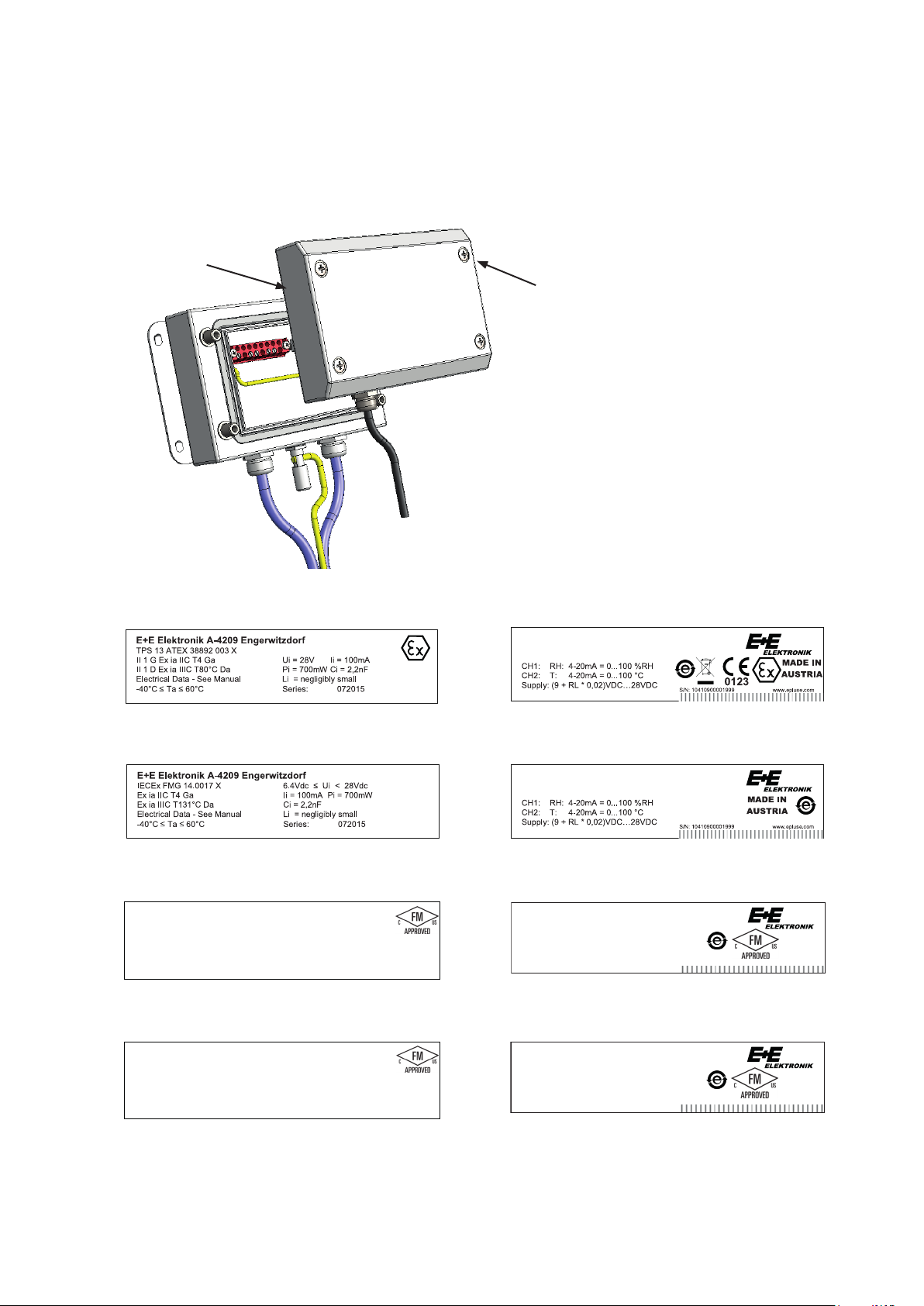
Each EE300Ex is characterized for one certification. The sensor has two labels. The “product label”
shows the ordering code and type of the Ex Certificate. The “hazardous label” shows the Ex marking
and the certificate number. See the examples below.
EE300Ex with IECEx, USA or Canada labeling must not be installed in the European Union.
Hazardous Label
(Ex marking)
Product Label
ATEX hazardous label (for EE300Ex without display) ATEX product label (Example)
EE300Ex-M1A6HS2T10D0E2K5L200PA25F4C1EX1
F
IECEx hazardous label (for EE300Ex without display) IECEx product label (Example)
EE300Ex-M1A6HS2T10D0E2K5L200PA25F4C1EX2
F
USA hazardous label (for EE300Ex without display) USA product label (Example)
EE300Ex-
CL I,II,III DIV 1 GP ABCDEFG T4
CL I,II,III DIV 2 GP ABCDEFG T4
CL I ZN 0 AEx ia IIC T4 Ga ZN 20 AEx ia IIIC T131°C Da
Ta = -40°C to 60°C, Entity - M1_1309080, IP65 Series:
122017
F
M1A6HS2T10D0E2K5L200PA25F4C1EX3
CH1: RH: 4-20mA = 0…100%RH
CH2: T: 4-20mA = 0…100°C
Supply: (9 + RL * 0,02)VDC…28VDC
S/N: 10410900001999 www.epluse.com
CANADA hazardous label (for EE300Ex without display) CANADA product label (Example)
EE300Ex-
CL I,II,III DIV 1 GP ABCDEFG T4
CL I,II,III DIV 2 GP ABCDEFG T4
ZN 0 Ex ia IIC T4 Ga ZN 20 Ex ia IIIC T131°C Da
Ta = -40°C to 60°C, Entity - M1_1309080, IP65 Series: 122017
F
M1A6HS2T10D0E2K5L200PA25F4C1EX9
CH1: RH: 4-20mA = 0…100%RH
CH2: T: 4-20mA = 0…100°C
Supply: (9 + RL * 0,02)VDC…28VDC
S/N: 10410900001999 www.epluse.com
AUSTRIA
AUSTRIA
User Manual EE300Ex Humidity / Temperature Sensor
7
Page 8
2.3 Certification
EUROPE:
The EE300Ex sensor fulfills the ATEX Directives on intrinsically safe operating equipment.
Applied standards for ATEX:
• EN 1127-1:2011
• EN 60079-0:2012
• EN 60079-11:2012
The EU-Type Examination has been carried out by TÜV SÜD Product Service GmbH.
Certified to EU-Type Examination TPS 13 ATEX 38892 003 X.
Entity parameters Ui = 28V; Ii = 100mA; Pi: = 700mW; Ci = 2,2nF; Li ≈ 0mH
Ex-Designation
Sensor without display I II 1G Ex ia IIC T4 Ga / II 1D Ex ia IIIC T80°C Da
Sensor with display I II 2G Ex ia IIC T4 Gb / II 1G Ex ia IIB T4 Ga
Remote probe II 1G Ex ia IIC T6-T1 Ga / II 1D Ex ia IIIC T80°C...200°C Da
Working temperature range for the probes:
Specification of the temperature class „TKG“ for use in gas area exposed to explosion hazards and
„TKD“ for use in dust area exposed to explosion hazards as a function of the ambient temperature
„Tamb“ for the humidity and temperature probe and the temperature probe:
TKG TKD
T6 80°C
T5 95°C
T4 130°C
T3 195°C
T2 200°C
T1 200°C
Humidity and
Temperature Probe
-40°C ≤ Tamb ≤ +60°C
-40°C ≤ Tamb ≤ +75°C
-40°C ≤ Tamb ≤ +110°C
-40°C ≤ Tamb ≤ +175°C
-40°C ≤ Tamb ≤ +180°C
-40°C ≤ Tamb ≤ +180°C
TKG TKD Temperature Probe
T6 80°C
T5 95°C
T4 130°C
T3 195°C
T2 220°C
T1 220°C
-70°C ≤ Tamb ≤ +60°C
-70°C ≤ Tamb ≤ +75°C
-70°C ≤ Tamb ≤ +110°C
-70°C ≤ Tamb ≤ +175°C
-70°C ≤ Tamb ≤ +200°C
-70°C ≤ Tamb ≤ +200°C
INTERNATIONAL:
Applied Standard for IECEx:
• IEC 60079-0:2011
• IEC 60079-11:2011
The Certificate of Conformity has been carried out by FM Approvals.
Certificate No.: IECEx FMG 14.0017 X
Entity parameters: 6.4 Vdc ≤ Ui ≤ 28Vdc; Ii = 100mA; Pi = 700mW; Ci = 2,2nF; Li = 0mH
Ex-Designation
Sensor without display Ex ia IIC T4 Ga / Ex ia IIIC T131°C Da
Sensor with display Ex ia IIC T4 Gb / Ex ia IIB T4 Ga
Remote probe Ex ia IIC T6-T1 Ga / Ex ia IIIC T80°C Da
Humidity and temperature probe:
• T6 temperature class based on -40°C (-40°F) ≤ Ta ≤ 60°C (140°F)
• T5 temperature class based on -40°C (-40°F) ≤ Ta ≤ 75°C (167°F)
• T4 temperature class based on -40°C (-40°F) ≤ Ta ≤ 110°C (230°F)
• T3 temperature class based on -40°C (-40°F) ≤ Ta ≤ 175°C (347°F)
• T2 temperature class based on -40°C (-40°F) ≤ Ta ≤ 180°C (356°F)
• T1 temperature class based on -40°C (-40°F) ≤ Ta ≤ 180°C (356°F)
8
User Manual EE300Ex Humidity / Temperature Sensor
Page 9

Temperature probe:
• T6 temperature class based on -70°C (-94°F) ≤ Ta ≤ 60°C (140°F)
• T5 temperature class based on -70°C (-94°F) ≤ Ta ≤ 75°C (167°F)
• T4 temperature class based on -70°C (-94°F) ≤ Ta ≤ 110°C (230°F)
• T3 temperature class based on -70°C (-94°F) ≤ Ta ≤ 175°C (347°F)
• T2 temperature class based on -70°C (-94°F) ≤ Ta ≤ 200°C (392°F)
• T1 temperature class based on -70°C (-94°F) ≤ Ta ≤ 200°C (392°F)
USA:
Applied Standard for the U.S. NEC 500, NEC505 and 506:
• FM Class 3600 2011
• FM Class 3610 2015
• FM Class 3611 2016
• FM Class 3810 2005
• ANSI/ISA 61010-1 2012
• ANSI/ISA 60079-0 2013
• ANSI/ISA 60079-11 2014
• ANSI/IEC 60529 2004
The Certificate of Conformity has been carried out by FM Approvals.
Certificate No.: FM17US0302X
Entity parameters:
6.4 Vdc ≤ V
(or Ui) ≤ 28 Vdc; I
max
(or Ii) = 100mA; Pi = 700mW; Ci = 2,2nF; Li = 0mH
max
Ex-Designation NEC 500 (Division)
Sensor without display
Class I, II, III, Division 1, Groups ABCDEFG; T4 Ta = -40°C to +60°C; Entity – M1_139080; IP65
Class I, II, III, Division 2, Groups ABCDEFG; T4 Ta = -40°C to +60°C
Sensor with display
Class I, Division 1, Groups CD; T4 Ta = -40°C to +60°C; Entity – M1_139080
Class I, Division 2, Groups ABCD; T4 Ta = -40°C to +60°C; Entity – M1_139080
Remote probe
Class I, II, III, Division 1, Groups ABCDEFG; T6…T1; Entity – M1_139080; IP65
Class I, II, III, Division 2, Groups ABCDEFG; T6…T1
Humidity and temperature probe:
• T6 temperature class based on -40°C (-40°F) ≤ Ta ≤ 60°C (140°F)
• T5 temperature class based on -40°C (-40°F) ≤ Ta ≤ 75°C (167°F)
• T4 temperature class based on -40°C (-40°F) ≤ Ta ≤ 110°C (230°F)
• T3 temperature class based on -40°C (-40°F) ≤ Ta ≤ 175°C (347°F)
• T2 temperature class based on -40°C (-40°F) ≤ Ta ≤ 180°C (356°F)
• T1 temperature class based on -40°C (-40°F) ≤ Ta ≤ 180°C (356°F)
Temperature probe:
• T6 temperature class based on -70°C (-94°F) ≤ Ta ≤ 60°C (140°F)
• T5 temperature class based on -70°C (-94°F) ≤ Ta ≤ 75°C (167°F)
• T4 temperature class based on -70°C (-94°F) ≤ Ta ≤ 110°C (230°F)
• T3 temperature class based on -70°C (-94°F) ≤ Ta ≤ 175°C (347°F)
• T2 temperature class based on -70°C (-94°F) ≤ Ta ≤ 200°C (392°F)
• T1 temperature class based on -70°C (-94°F) ≤ Ta ≤ 200°C (392°F)
User Manual EE300Ex Humidity / Temperature Sensor
9
Page 10

Ex-Designation NEC 505/506 (Zone)
Sensor without display
Class I, Zone 0, AEx ia IIC T4 Ta = -40°C to +60°C Ga; Entity – M1_139080; IP65
Zone 20, AEx ia IIIC T131°C Ta = -40°C to +60°C Da; Entity – M1_139080; IP65
Sensor with display
Class I, Zone 0, AEx ia IIB T4 Ta = -40°C to +60°C Ga; Entity – M1_139080
Class I, Zone 1, AEx ia IIC T4 Ta = -40°C to +60°C Gb; Entity – M1_139080
Remote probe
Class I, Zone 0, AEx ia IIC T6…T1 Ga; Entity – M1_139080; IP65
Zone 20, AEx ia IIIC T80°C Da; Entity – M1_139080; IP65
Humidity and temperature probe:
• T6 temperature class based on -40°C (-40°F) ≤ Ta ≤ 60°C (140°F)
• T5 temperature class based on -40°C (-40°F) ≤ Ta ≤ 75°C (167°F)
• T4 temperature class based on -40°C (-40°F) ≤ Ta ≤ 110°C (230°F)
• T3 temperature class based on -40°C (-40°F) ≤ Ta ≤ 175°C (347°F)
• T2 temperature class based on -40°C (-40°F) ≤ Ta ≤ 180°C (356°F)
• T1 temperature class based on -40°C (-40°F) ≤ Ta ≤ 180°C (356°F)
Temperature probe:
• T6 temperature class based on -70°C (-94°F) ≤ Ta ≤ 60°C (140°F)
• T5 temperature class based on -70°C (-94°F) ≤ Ta ≤ 75°C (167°F)
• T4 temperature class based on -70°C (-94°F) ≤ Ta ≤ 110°C (230°F)
• T3 temperature class based on -70°C (-94°F) ≤ Ta ≤ 175°C (347°F)
• T2 temperature class based on -70°C (-94°F) ≤ Ta ≤ 200°C (392°F)
• T1 temperature class based on -70°C (-94°F) ≤ Ta ≤ 200°C (392°F)
Canada:
Applied Standard for Canada CEC Section 18 and Annex J:
• CSA-22.2 No. 0-M91 R2006
• CAN/CSA-22.2 No. 61010-1 2012
• CSA-22.2 No. 157-92 2016
• CAN/CSA-22.2 No. 60079-0 2015
• CAN/CSA-22.2 No. 60079-11 2014
• CSA-C 22.2 No. 142-M1987 R2004
• CSA-C 22.2 No. 213 2015
• CSA-C 22.2 No. 60529 R2010
The Certificate of Conformity has been carried out by FM Approvals.
Certificate No.: FM17CA0154X
Entity parameters:
6.4 Vdc ≤ V
Ex-Designation CEC Annex J (Division)
Sensor without display
Class I, II, III, Division 1, Groups ABCDEFG; T4 Ta = -40°C to +60°C; Entity – M1_139080; IP65
Class I, II, III, Division 2, Groups ABCDEFG; T4 Ta = -40°C to +60°C
(or Ui) ≤ 28 Vdc; I
max
(or Ii) = 100mA; Pi = 700mW; Ci = 2,2nF; Li = 0mH
max
10
Sensor with display
Class I, Division 1, Groups CD; T4 Ta = -40°C to +60°C; Entity – M1_139080
Class I, Division 2, Groups ABCD; T4 Ta = -40°C to +60°C; Entity – M1_139080
User Manual EE300Ex Humidity / Temperature Sensor
Page 11

Remote probe
Class I, II, III, Division 1, Groups ABCDEFG; T6…T1; Entity – M1_139080; IP65
Class I, II, III, Division 2, Groups ABCDEFG; T6…T1
Humidity and temperature probe:
• T6 temperature class based on -40°C (-40°F) ≤ Ta ≤ 60°C (140°F)
• T5 temperature class based on -40°C (-40°F) ≤ Ta ≤ 75°C (167°F)
• T4 temperature class based on -40°C (-40°F) ≤ Ta ≤ 110°C (230°F)
• T3 temperature class based on -40°C (-40°F) ≤ Ta ≤ 175°C (347°F)
• T2 temperature class based on -40°C (-40°F) ≤ Ta ≤ 180°C (356°F)
• T1 temperature class based on -40°C (-40°F) ≤ Ta ≤ 180°C (356°F)
Temperature probe:
• T6 temperature class based on -70°C (-94°F) ≤ Ta ≤ 60°C (140°F)
• T5 temperature class based on -70°C (-94°F) ≤ Ta ≤ 75°C (167°F)
• T4 temperature class based on -70°C (-94°F) ≤ Ta ≤ 110°C (230°F)
• T3 temperature class based on -70°C (-94°F) ≤ Ta ≤ 175°C (347°F)
• T2 temperature class based on -70°C (-94°F) ≤ Ta ≤ 200°C (392°F)
• T1 temperature class based on -70°C (-94°F) ≤ Ta ≤ 200°C (392°F)
Ex-Designation CEC Section 18 (Zone)
Sensor without display
Zone 0, Ex ia IIC T4 Ta = -40°C to +60°C Ga; Entity – M1_139080; IP65
Zone 20, Ex ia IIIC T131°C Ta = -40°C to +60°C Da; Entity – M1_139080; IP65
Sensor with display
Zone 0, Ex ia IIB T4 Ta = -40°C to +60°C Ga; Entity – M1_139080
Zone 1, Ex ia IIC T4 Ta = -40°C to +60°C Gb; Entity – M1_139080
Remote probe
Zone 0, Ex ia IIC T6…T1 Ga; Entity – M1_139080; IP65
Zone 20, Ex ia IIIC T80°C Da; Entity – M1_139080; IP65
Humidity and temperature probe:
• T6 temperature class based on -40°C (-40°F) ≤ Ta ≤ 60°C (140°F)
• T5 temperature class based on -40°C (-40°F) ≤ Ta ≤ 75°C (167°F)
• T4 temperature class based on -40°C (-40°F) ≤ Ta ≤ 110°C (230°F)
• T3 temperature class based on -40°C (-40°F) ≤ Ta ≤ 175°C (347°F)
• T2 temperature class based on -40°C (-40°F) ≤ Ta ≤ 180°C (356°F)
• T1 temperature class based on -40°C (-40°F) ≤ Ta ≤ 180°C (356°F)
Temperature probe:
• T6 temperature class based on -70°C (-94°F) ≤ Ta ≤ 60°C (140°F)
• T5 temperature class based on -70°C (-94°F) ≤ Ta ≤ 75°C (167°F)
• T4 temperature class based on -70°C (-94°F) ≤ Ta ≤ 110°C (230°F)
• T3 temperature class based on -70°C (-94°F) ≤ Ta ≤ 175°C (347°F)
• T2 temperature class based on -70°C (-94°F) ≤ Ta ≤ 200°C (392°F)
• T1 temperature class based on -70°C (-94°F) ≤ Ta ≤ 200°C (392°F)
User Manual EE300Ex Humidity / Temperature Sensor
11
Page 12
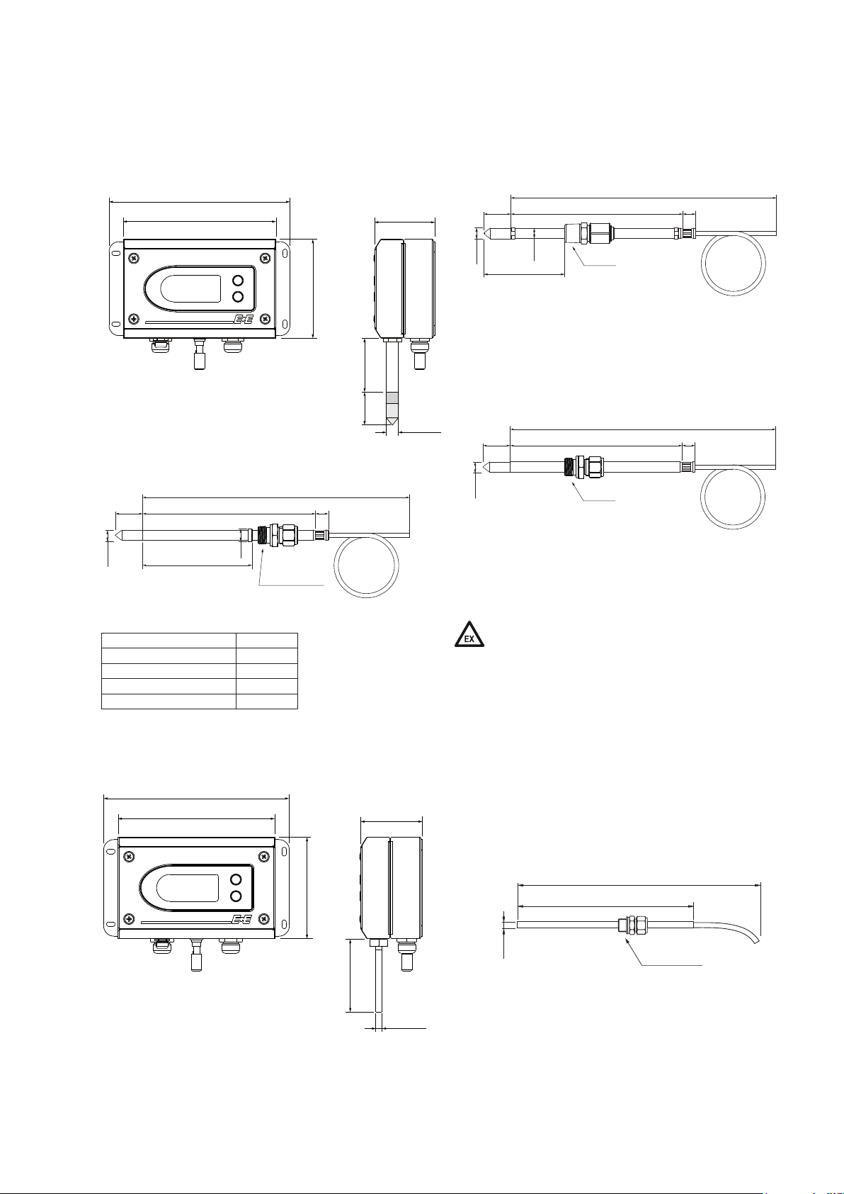
2.4 Dimensions (mm / inch)
2.4.1 EE300Ex-M1: Humidity and Temperature Sensor
179 (7)
98 (3.9)
Types: T1 / T7 / T9 / T10 / T22
Enclosure
code „cable length“
(11.81)
Ø12
L
(0.47)
186 (7.32)
300
Ø15
(0.6)
G1/2“ ISO
Type: T22
Remote probe for sensor retraction tool PN250
L - length of filter mm (inch)
Stainless steel sintered filter 33 (1.3“)
PTFE filter, H2O2 filter 33 (1.3“)
Stainless steel grid filter 39 (1.5“)
Oil filter 32 (1.26“)
15 (0.6)
60 (2.4)151 (5.9)
53 (2.1)
L
Type: T1
Wall mount
Ø 12 (0.47)
code „cable length“
L
Ø13
(0.51)
adjustable min. 23 (0.9) /
max. 164 (6.5) / 364 (14.3)
Ø12
(0.47)
code „probe length “
G1/2" ISO or 1/2“ NPT
15 (0.6)
Type: T10
Remote probe 20 bar (300 psi) with sliding fitting for assembly /
disassembly under pressure
code „cable length“
15 (0.6)
Ø12
(0.47)
L
code „probe length “
G1/2" ISO or 1/2" NPT
Types: T7 / T9
Remote probe T7: 20 bar (300 psi)
Remote probe T9: 300 bar
Pressure-tight probe up to 300 bar (4 351 psi) has leak rate A
according to EN 12266-1
Pressure-tight probe up to 20 bar (300 psi) has leak rate B
according to EN 12266-1
Leak rate can lead to gas accumulation in the enclosure
(4 351 psi) with weld or cut-in fitting
2.4.2 EE300Ex-M3: Temperature Sensor
179 (7)
151 (5.9)
98 (3.9)
Types: T1/T24
Enclosure
12
70 (2.8)
Type: T1
Wall mount
60 (2.4)
Ø 6 (0.24)
code „cable length“
150 (6)
Ø 6 (0.24)
G1/2" ISO or 1/2“ NPT
Type: T24
Remote probe 0.1...20bar (1.5...300psi) with cut-in fitting
User Manual EE300Ex Humidity / Temperature Sensor
Page 13
3 Installation
3.1 General
The EE300Ex is certified according to ATEX 2014/34/EU Directive, IECEX Scheme, National Electrical
Code ANSI-NFPA 70 (NEC©) and Canadian Electrical Code (CSA C22.1).
The use of the EE300EX in explosion hazard areas is only permitted under following atmospheric conditions:
-20°C(-4°F) ≤T≤ 40°C(104°F)
0.8bar(12psi)≤p≤ 1.1bar(16psi)
air normally 21 % (v/v)
The EE300Ex may be employed beyond above atmospheric conditions range only observing EN 1127-1
and only in line with the manufacturer‘s instructions.
The EE300Ex may only be supplied by intrinsically safe power supply devices or via protective barriers.
This applies also for the case when just the probe is located inside the explosion hazard area.
The rules for wiring intrinsically safe electrical circuits according to EN 60079-14, EN 60079-25, IEC
60079-14, IEC 60079-25 (proof of intrinsic safety in the system description) as well as all applicable
national regulations must be strictly observed. For the U.S., Canada refer to the Control
Drawing M1_1309080 (page 51) and ANSI/ISA RP12.6.01, NEC and CEC.
The intrinsically safe circuitry shall include an overvoltage protection device if the analysis according EN
1127-1 reveals a risk of lightning strike.
Requirements for the installation of overvoltage protection devices are set in European Normative EN
60079-25. For the U.S., Canada refer to ANSI/ISA RP12.6.01, NEC and CEC.
The manufacturing date of each EE300Ex is shown on the hazardous product label, at the bottom right
corner, as follows:
WWYYYY
WW .........week of the year
YYYY ........ year
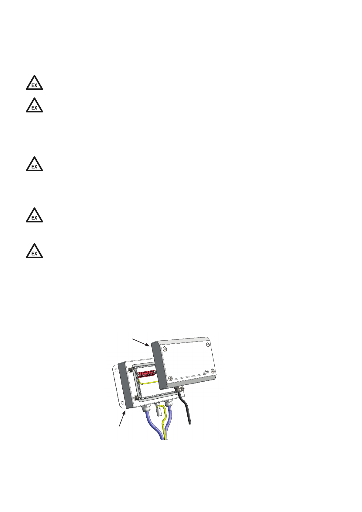
3.2 Enclosure
The EE300Ex features has a modular design and consists of:
• Bottom section with the connection and grounding terminals
• Front section with the electronics and the probe
front section
bottom section
User Manual EE300Ex Humidity / Temperature Sensor
13
Page 14
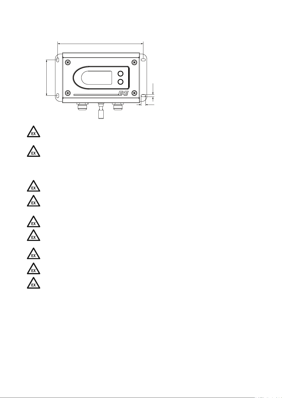
3.2.1 Drilling pattern for installing the enclosure (mm/inch)
167 (6.6“)
70 (2.8“)
4.5 (0.18“)
8.4 (0.33“)
When the front section has been removed from the hazard area, e.g. for calibration, the empty bottom
section shall be protected against dirt and electrostatic charge with the blind front cover HA011401 (see
accessories).
Unused cable glands shall be closed with appropriate sealing plugs (see accessories).
To mount the bottom section use
4 screws diameter < 4.5 mm
(0.18“)
3.3 Assembly in category 1 (Zone 0 / 20); Division 1
Only intrinsically safe power supply devices are approved to supply EE300Ex in category 1 or Division 1.
In areas belonging to gas group IIC or Class I, Division 1, Group A, B, it must be ensured that during
installation and operation, the possibility of impact and friction sparks has been excluded in rarely
occurring fault situations.
Work on open sensor must only be performed if it is guaranteed that no explosive atmosphere is present.
In category 1 or Division 1, the sensor line should be laid in an earthed metallic protective hose. With
Group III or Class II, III, ensure that there are no dust or fibers and flyings deposits in the protective
tube.
CH1 and CH2 must be galvanically isolated from one another during operation.
There is no display permitted in the gas hazard area EPL Ga for Group IIC or Class I,
Division 1, group A, B and in the dust hazard area for groups IIIA, IIIB and IIIC or Class II, III.
The probe for wall mount is not permitted to be used for Zone or Division bushing.
14
User Manual EE300Ex Humidity / Temperature Sensor
Page 15
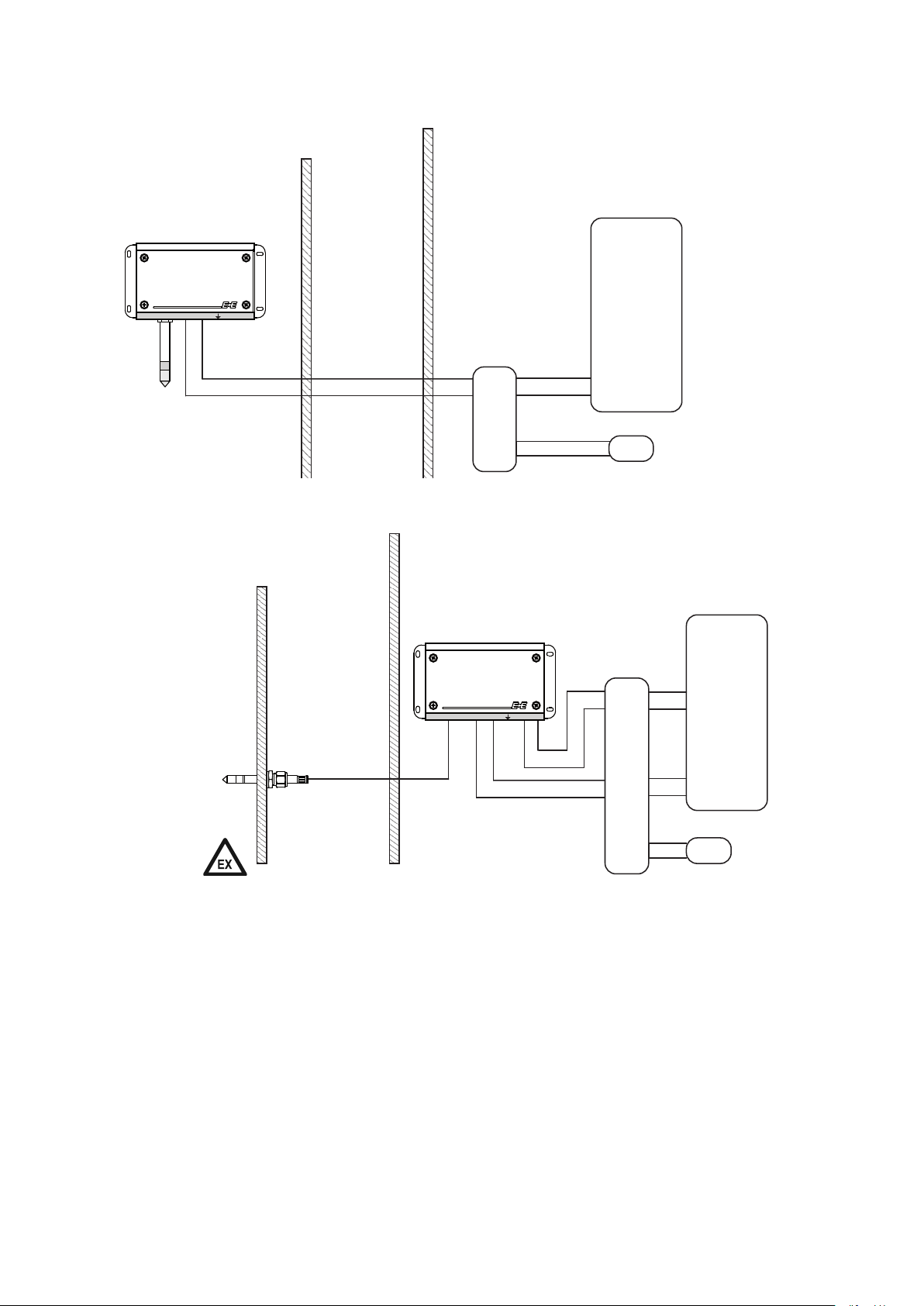
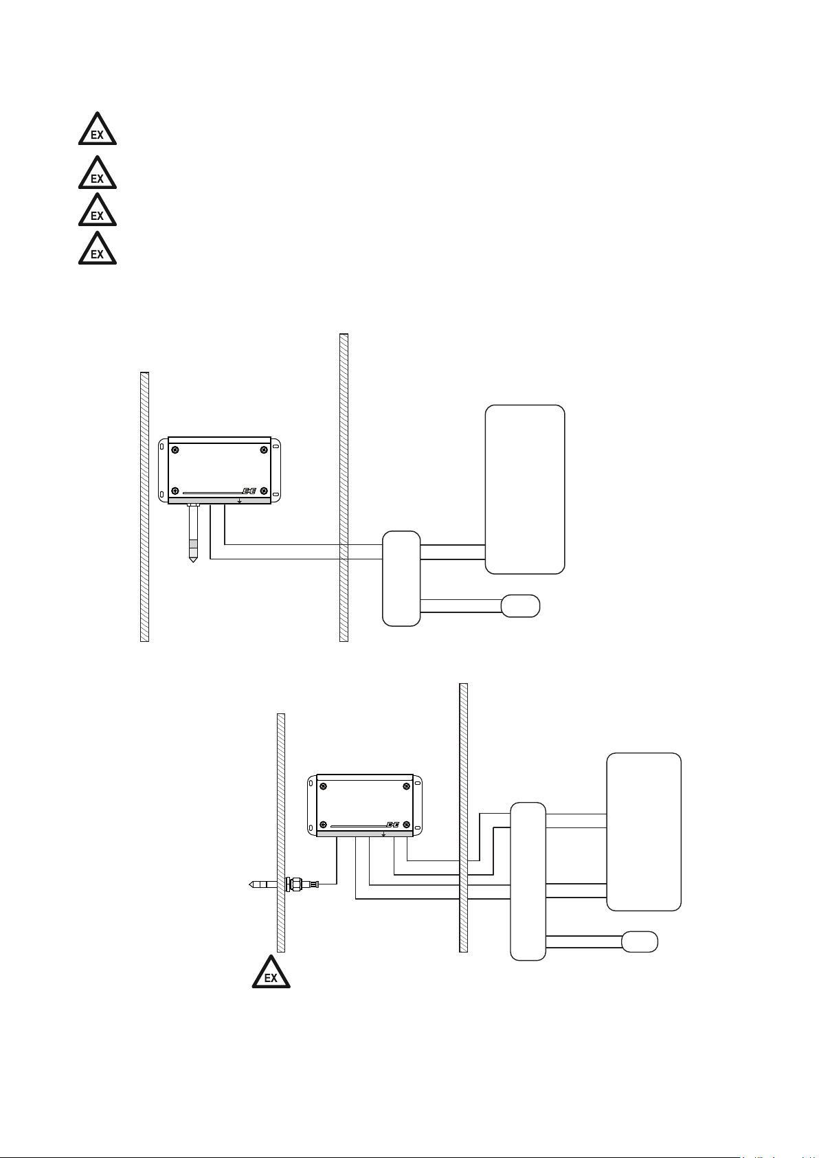
EE300Ex (wall mount) 1 channel via intrinsically safe power supply device:
Hazardous location T4...T1
Zone 0 / 20
no display with EPL Da; Db, Dc
and Ga IIC
Division 1
no display in Class II, III and
Class I, Division 1, Group A, B
CH1
CH2
Zone 1 2 / 21 22
Division 2
Unclassified location
Control
intrinsically safe
sensor supply unit
+
4-20mA ia
+
-
-
L+
L-
+
-
Power supply
EE300Ex (with remote probe) 2 channels via intrinsically safe power supply device:
Hazardous location T6...T1
Unclassified location
Zone 0 / 20
Division 1
Class I,II,III
Group A, B, C, D, E, F, G
up to T6 if EE300Ex is in
unclassified location.
Zone 1 2 / 21 22
Division 2
Class I,II,III
Group A, B, C, D, E, F, G
The bushing must
conform to the hazard requirements
of a Zone or Division implementation.
The supplied screw
connection meets
this requirement!
intrinsically safe
sensor supply unit
+
+
-
CH1
CH2
4-20mA ia
4-20mA ia
-
+
+
-
-
L+
L-
Control
+
-
Power supply
User Manual EE300Ex Humidity / Temperature Sensor
15
Page 16
3.4 Assembly in categories 2 and 3 (Zone 1 , 2 / 21 , 22); Division 2
4-20mA ia
4-20mA ia
+
-
L+
L-
+
-
+
-
+
-
+
-
CH2
CH1
Only intrinsically safe power supply devices and protective barriers are approved to supply EE300Ex in
category 2 and 3 or Division 2.
No display is permitted in the dust hazard area (Group III) or Class II, III.
CH1 and CH2 must be galvanically isolated from one another during operation.
The probe for wall mount is not permitted to be used for Zone or Division bushing.
EE300Ex (wall mount) 1 channel via intrinsically safe power supply device:
Hazardous location T4...T1 Unclassified location
Zone 1 2 / 21 22
Division 2
Class I,II,III
Group A, B, C, D, E, F, G, H
CH1
CH2
intrinsically safe
sensor supply unit
Control
+
4-20mA ia
+
-
-
L+
L-
+
-
Power supply
EE300Ex (with remote probe) 2 channels via intrinsically safe power supply device:
Hazardous location T4...T1 Unclassified location
Zone 0 / 20
Division 1
Class I,II,III
Group A, B, C, D, E, F, G, H
Zone 1 2 / 21 22
Division 2
Class I,II,III
Group A, B, C, D, E, F, G, H
intrinsically safe
sensor supply unit
Control
16
The bushing must conform
to the hazard requirements
of a Zone or Division implementation. The supplied
Power supply
screw connection meets
this requirement!
User Manual EE300Ex Humidity / Temperature Sensor
Page 17
3.5 Probe mounting
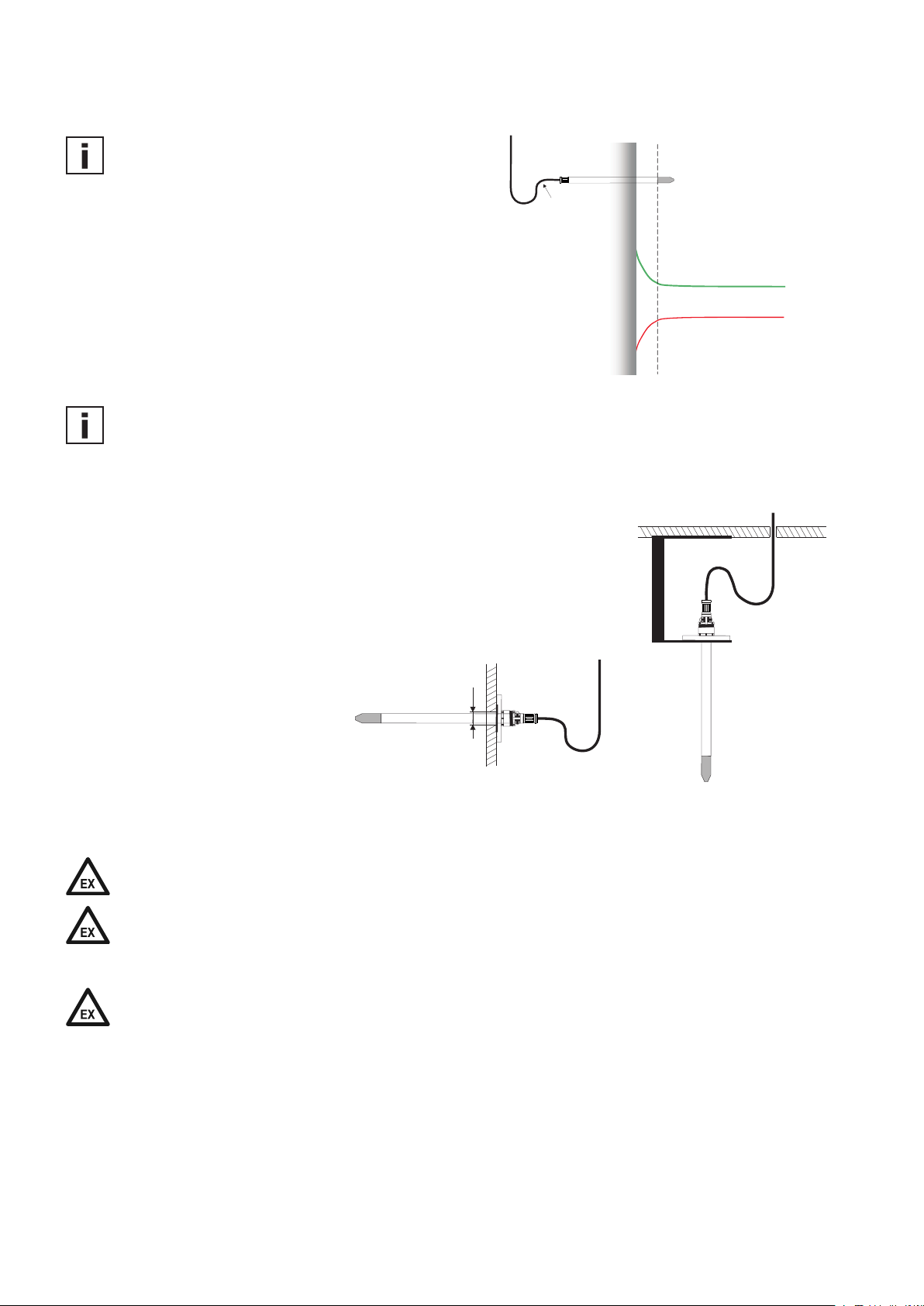
The probe of the EE300EX sensor shall be located
at the most representative location for the RH and
T of the process to be monitored.
For accurate measurement it is of paramount
importance to avoid temperature gradients along
the probe.
Whenever possible, install the entire probe inside
the environment to monitor. If the probe is installed
into a wall, than isolate thermally the backend of
the probe looking out of the wall.
The probe shall be mounted horizontally or vertically, with the tip of the probe pointing downwards.
In applications where condensation is likely to happen:
• The cable shall form a drip
loop close to the probe.
• Use the drip water protection
(see datasheet accessories,
code HA010503) for vertically
mounted probe.
r>30mm
Wall
60% rH
17°C
Relative Humidity
Temperature
45% rH
21°C
Ø 13mm (0.5")
Horizontal mounting
Vertical mounting
Ensure appropriate mechanical stability and sealing of the probe mounting taking into account specific
influences at the site, such as vibrations, shocks or temperature changes.
The probe and the cabling shall be handled and installed to avoid electrostatic charges. (e.g. metal
hose)
Filter caps
The following filter caps offer good protection against electrostatic discharge for explosion group IIB, but
are not permitted for use in EPL Ga IIC or Class I, Division 1, Group A, B:
• Membrane filter (order code F2)
• PTFE filter(order code F5)
• Membrane on stainless steel body (order code F10)
• PTFE on stainless steel body (order code F11)
• H2O2 filter (order code F12)
User Manual EE300Ex Humidity / Temperature Sensor
17
Page 18

The following filter caps are permitted for use in EPL Ga IIC or Class I, Division 1, Group A, B:
• Stainless steel sintered (order code F4)
• Stainless steel grid (order code F9)
• Oil (order code F13)
3.5.1 Probe feedthrough with cut-in fitting
The feedthrough with cut-in fitting (ordering code PA20, PA21, PA22) can be used as Zone or Division
bushing. For this, the tightness of its mounting into the Zone separation wall must correspond to IP67.
Once mounted, the cut-in fitting creates a permanent clamping-ring onto the probe.
Safety instructions for pressure-tight feedthrough:
• Do not assemble the probe and tighten the feedthrough if the plant is under pressure.
• The plant must not be vented by releasing the nut (A).
• Use appropriate seal on conical probe threads.
• Never rotate the screw connection body (B) but hold the screw connection body (B) securely and turn
the nut (A).
• Avoid unnecessary disassembly of pipe screw connections.
• Position the cut in fitting >75 mm (2.95”) from the end of the filter cap to the end of the fitting!
For a probe length of 65 mm a cut in fitting is not possible.
>75 mm (2.95“)
Installation instructions:
• Tighten the nut (A) finger-tight.
• Mark the nut (A) at 6 o‘ clock position.
• Hold the screw connection body (B) tight and tighten the nut (A) with
1 ¼ turns till 9 ‚o clock position.
Assembly with high pressure applications and applications with a
high security factor:
• Tighten the nut (A) until the probe (C) can no longer be turned by
hand and moved axially in the feedthrough.
• Mark the nut (A) at 6 o‘ clock position.
• Hold the screw connection body (B) tight and tighten the nut (A) with
1 ¼ turns to 9‚ o clock position.
Re-mounting:
• Slide the measurement probe with clamping ring into the fitting as far
as it goes.
• Tighten the nut finger-tight, then tighten by approx. a ¼ turn using a
spanner.
A
B
B
A
B
A
C
18
User Manual EE300Ex Humidity / Temperature Sensor
Page 19

3.5.2 Mounting flange
The optional mounting flange (see datasheet accessories) may not be used as Zone or Division
bushing. When installed with the mounting flange, the hazard areas on the filter cap side and at the
cable outlet side must be of the same category.
HA010207
HA010201
3.5.3 Ball valve and sliding fitting
The optional ball valve HA011403 (ATEX certified)
allows for the probe to be mounted or removed without
interrupting the process to be monitored.
Only ball valve approved for use in explosion hazard
areas are permitted.
The two metal sealing rings (see figure) shall be
replaced with new ones after each removal of the
probe.
MOUNTING THE PROBE:
The process temperature may not deviate from the
mounting temperature by more than ±40 °C (104 °F).
The maximum permitted process pressure during
mounting is 10 bar (145 psi).
• Mount the probe onto the ball valve with the ball
valve closed.
• Open the ball valve.
• Slide the probe through the ball valve into the process to the desired immersion depth. For rather high process pressure a manual pressing tool might
be needed for sliding easily the probe into the process.
• For secure probe installation the closing nut shall be tightened with a torque of 30 Nm. If a torque
wrench is not available, turn first the closing nut by hand as tight as possible, then turn another
approx. 50° using a suitable open-ended spanner.
A lower tightening torque means lower clamping force of the clamp sleeve. Consequently there is a
risk for the probe being pushed out by the process pressure.
An excessive tightening torque may cause permanent deformation of the clamping sleeve and of the
probe. This makes the removal and re-mounting difficult or even impossible.
HA011403
Metal sealing ring
(as standard
with probe)
Extension
(not provided with an
NPT thread)
Metal sealing ring
(included with the ball
valve set as standard)
Internal diameter:
≥ 13.1 mm (0.51")
User Manual EE300Ex Humidity / Temperature Sensor
19
Page 20

REMOVING THE PROBE:
• Hold the probe firmly in place. While doing so, do not
bend the probe cable.
• Release slowly closing-nut using a spanner only until
the process pressure pushes out the probe. Do not
release completely the closing-nut!
• After the probe has been pushed all the way back,
close the ball valve.
• The probe can be now removed from the ball valve.
During mounting and removal, ensure that o-ring 1 is
correctly installed.
Replace a damages o-ring by an original new one,
order code HA050308, o-ring type: 13x1.5mm
(0.5“x 0.06“) - FKM-60.
3.5.4 The optional probe retraction tool
Sealing nut
Fitting body
Clamp sleeve
O-ring 2
O-ring 1
no aluminium
is permitted
The operating instructions of the probe retraction tool must be strictly observed.
The probe of the EE300EX model T22 can be installed into a pressurized environment up to 250 bar
using the sensor retraction tools ZM-WA-025-040-EST or BG-WA-103-045-EST.
The scope of supply of the EE300EX model T22 includes the copper sealing for the Swagelok
feedthrough.
Make sure that the sensor retraction tool is in the ”SERVICE“ position (see manual of the sensor
retraction tool).
• Before installing the sensor, dismount the closing plug ½“ using a
hexagonal 10 mm wrench and “park“ it at the thread hole M10
designed for that purpose.
• Insert the probe with the copper sealing, the Swagelok
union nut, the Swagelok fitting and protective cover into
the probe retraction tool as far as it goes.
protective cover
Swagelok-nut
20
Swagelok-tting
copper sealing
User Manual EE300Ex Humidity / Temperature Sensor
Page 21

• Fasten the Swagelok ½“fitting of the sensor retraction tool with appropriate wrench. Do not forget the
copper sealing!
• Close the Swagelok union nut with cutting ring finger-tight by hand.
Then adjust the probe.
• Use the appropriate wrench to tighten the union nut (A) just firmly enough
that the screw connection (B) cannot be moved manually. Mark the nut
at the 6 o‘ clock position.
• Hold the screw connection body (B) tight and tighten the union nuts (A)
with 1 ¼ turns to the 9 o‘ clock position.
• Mounting the protective cover for the Swagelok feedthrough:
1. Push the protective cover down to the adjusting device. The screws
shall point to the flat area.
2. Tighten the M3 screws.
4 Electrical connections
4.1 General
It is essential that installation, electrical connection, commissioning, operation and maintenance in
explosion hazard areas are only carried out by trained specialist staff authorised to do so by the system
operator.
The installation shall be performed according to NEC or CEC and to the Control Drawing M1_1309080
(page 50).
The installation in an explosion hazard area shall comply with EN 60079-14, EN 60079-25 or
IEC 60079-14, IEC 60079-25. Repair and maintenance shall be performed according to EN 60079-17 or
IEC 60079-17 and EN 60079-19 or IEC 60079-19.
All relevant national regulations shall be strictly observed.
Installation in the U.S. shall be performed according ANSI / ISA RP 12.6.01-2003 and
the National Electrical Code (NEC).
Installation in Canada shall comply with the Canadian Electrical Code (CEC).
The EE300Ex sensor is a loop powered (2-wire) device, both channels (outputs) are galvanic isolated.
For proper operation, Channel 1 (CH1) must always be connected. Channel 2 (CH2) may be
connected only if necessary.
Cable ends shall be fitted with the appropriate wire-end sleeves. While connected to the
terminals, the air gap must be min 2mm (0.08“) between the wires and min. 6mm (0.2“) between CH1
and CH2.
Do not shorten or extend the probe cable. Changing the length of the probe cable has a strong negative
effect onto the measurement performance and may lead to EE300EX failure.
User Manual EE300Ex Humidity / Temperature Sensor
21
Page 22

4.2 Terminal assignment
GROUND
CH1 +
CH1 -
CH2 +
CH2 -
4.3 Grounding and potential equalization
The EE300Ex shall be integrated into the potential equalization to avoid hazards from electrostatic
charges. The grounding shall comply with EN60079-14, EN60079-25 or IEC60079-14, IEC60079-25. A
remote probe shall also be grounded using a screw connection with a maximum of 1 MΩ in the potential
equalization.
The ground conductor or the potential equalization connection must have a cross-section of 4 mm²
(0.06 in²) for the external grounding. Stranded wires shall be fitted with suitable wire-end sleeves.
The resistance of the ground connection of the intrinsically safe barrier shall be max. 1 Ohm.
For installation in the U.S. use internal ground connection. The wire cross-sectional must comply with
NEC Section 250.122.
External grounding:
22
Internal grounding:
Cable cross-section
maximum 4mm² (0.06in²)
Grounding connection channel 1
Grounding connection channel 2
Grounding connection occupied
Cable cross-section
maximum 10 mm² (0.2 in
User Manual EE300Ex Humidity / Temperature Sensor
2
)
Page 23

1)
EXPLOSIONSGEFÄHRDETER
Hazardous location
BEREICH
CH1 +
CH2 +
Erde
CH1 -
CH2 -
1)
potential equalization connection
Unclassified location
SICHERER BEREICH
Instrument
Instrument
System
System
Sicherheits-
Safety barrier
barriere oder
or power
Speisegerät
supply unit
Erdung der Barrieren
grounding of barriers
central grounding
Zentrale Erdung
The braided screen should be turned back via the plastic insert on
the cable connection. The introduction of the plastic insert presses
the braided screen onto the interior wall of the metallic part.
4.4 Connection cable
A shielded cable shall be used. The shield must be grounded only at one end, at the EE300Ex side.
The connection cable shall comply to the following specifications for ATEX, as required by EN60079-14
and EN60079-25:
• Maximum cross-section 1.5mm² (0.02in²)
• Single stranded wire diameter ≥ 0.1mm (0.004“)
• Test voltage wire-wire ≥ 500V AC eff.
• Test voltage wire-shield (if a cable with shield is used): ≥ 500V AC eff.
• Cable inductivity, cable capacity and conductor resistance are to be evaluated during the proof of
intrinsic safety.
• Flame resistance acc. to IEC60332-1-2
Example of cable meeting above requirements: ÖLFLEX® EB CY from LAPP KABEL
Additional requirements if both channels (CH1, CH2) are connected with a common cable:
• The test voltage wire-wire ≥ 1000 V AC eff.
• The radial thickness of the insulation ≥ 0.2 mm (0.008").
• The conductor insulation shall withstand 500 V AC eff.
4.5 Calculation of the maximum cable length
Intrinsically safe power supply device STAHL 9160/13-11-11 (order code HA011405)
Technical data for EE300Ex
Supply voltage: U
Max. current: I
Bin
out max
Technical data for STAHL 9160/13-11-11
Nominal operating voltage: UN = 24 V
Input voltage for sensor: US = 16 V
Max. load: RL = 600 Ohm
User Manual EE300Ex Humidity / Temperature Sensor
= 9V + RL * 0.02A
= 20mA
23
Page 24

Example: Calculation of maximum cable length
Cable 0.75mm² (0.01in
2
): R
= 0.0267 Ω/m
cable
Load resistor: RL = 200 Ω
Input voltage for sensor: VS= 16 V
Min. supply voltage EE300Ex: V
= 9V + 200Ω * 0.02A = 13V
Bmin
Maximum voltage drop on cable: V
Total cable resistance: R
V
= R
Transform in accordance with L
total
L
L
L
= VS - V
cable
cable total
drop
total
total
total
= R
= R
cable total
cable
= V
drop
= 3V / (0.02A * 2 * 0.0267Ω/m )
= 2800m maximum cable length
= 16V – 13V = 3V
Bmin
* L
cable
* L
/ (I
out max
* 2 (supply and return line)
total
* I
out max
* 2 * I
total
* 2 * R
=
out max
cable
)
Caution: This is the maximum length without allowing the intrinsic safety area. Cable capacity
and inductivity may reduce the cable length.
4.6 Selecting a suitable Intrinsically safe supply unit for ATEX Zone concept
Example for evidence of the intrinsic safety in accordance with EN 60079-14:2008 12.2.5.2,
EN 60079-25:2010 13.1. CH1 and CH2 are galvanically isolated. The proof of intrinsic safety shall be
performed with appropriate equipment.
Example: Installation in Zone 0 of the EE300Ex without display
Connection cable length: 300 m (984 ft)
Explosion group: IIC
Temperature class: T4
CH1 and CH2 connected by one single cable.
Intrinsically safe power supply device STAHL 9160/13-11-11 (see accessories)
(Extract from the EC-Type Examination Certificate)
Certified according to:
II 3 (1) G Ex nA nC [ia Ga] IIC T4 Gc (certificate number: DMT 03 ATEX E 010 X)
II (1) D [Ex ia Da] IIIC (certificate number: DMT 03 ATEX E 010 X)
Entity parameters:
U0 = 27 V
I0 = 88 mA
P0 = 576 mW
C0 IIC = 90 nF
C0 IIB = 705 nF
L0 IIC = 2.3 mH
L0 IIB = 17 mH
Technical data for the connection cable:
Cable type: ÖLFLEX® EB CY from Lapp Kabel
Cable cross-section: 4 x 0.75 mm² (0.06x0.01 in²)
Operating capacity: 110 nF/km
Inductivity: 0.65 mH/km
Cable capacity for 300m (984ft): CK = 0.3km * 110nF/km = 33nF
Cable inductivity for 300m (984ft): LK = 0.3km * 0.65mH/km = 0.195mH
24
User Manual EE300Ex Humidity / Temperature Sensor
Page 25

Technical data for EE300Ex (extract from the EU-Type Examination Certificate):
Certified according to:
II 1G Ex ia IIC T4 Ga
II 1D Ex ia IIIC T80°C Da
Entity parameters:
Ui = 28V
Ii = 100mA
Pi = 700mW
Ci = 2.2nF
Li = negligibly small
Proof of the intrinsic safety according EN 60079-11:2012
EN 60079-25:2010 (Appendix A)
U0 = 27V ≤ Ui = 28V → ok
I0 = 88mA ≤ Ii = 100mA → ok
P0 = 576mW ≤ Pi = 700mW → ok
C0 = 90nF ≥ 2,2nF + 33nF → ok
L0 = 2,3mH ≥ 0mH + 0,195mH → ok
Conclusion: The protection level of the intrinsically safe current circuit is met.
Proof of the intrinsic safety according EN 60079-11:2012,
EN 60079-25:2010 (Appendix A)
Li=0
YES
Full values of C
NO
C
=0
i
YES
and L0 can be
0
utilised
Li = negligibly small → no reduced C0 and L0 values are required.
4.7 Configuration adapter
L
of L
YES
NO
≤1%
i
0
NO
Ci≤1%
of C
YES
NO
0
Use reduced C
and L0 values for
0
mixed electric circuits
For intrinsically safe electric circuits with
linear sources, simplied evaluation rule:
each half value of C
and L0 can be used,
0
limited to C0 = 600 nF (IIC) and 1 μF (IIB)
The on-board service interface is dedicated for the EE300EX configuration and for the RH and T adjustment. This is possible by the optional EE-PCA Product Configuration Adapter and HA011068 connection cable. Refer to datasheet EE-PCA and HA011068 user manual.
The EE-PCS configurator software and the drivers are available for download free of charge at
http://www.epluse.com/en/service-support/download-center/
User Manual EE300Ex Humidity / Temperature Sensor
25
Page 26

The configuration or adjustment of EE300Ex may not be performed in the hazard area.
CH1 and CH2 must be disconnected while using the configuration adapter.
When the front section has been removed from the hazard area, e.g. for calibration, the empty bottom
section shall be protected against dirt and electrostatic charge with the blind front cover HA011401 (see
accessories).
4.8 Calibration of the current loop
For the calibration of the current loop in explosion hazard areas only approved multimeters are permitted. During the measurement with these multimeters the requirements of the system description (the
proof of intrinsic safety) shall be observed
5 Display (optional)
Display is not permitted in the gas hazard area for EPL Ga IIC or Class I, Division 1,
Group A, B and in the dust hazard area for IIIA, IIIB and IIIC or Class II, III
The display shows the measured parameter on the outputs CH1 (top row) and CH2 (bottom row),
according the ordering code.
The top key change the visualization of the calculated parameter on the top row. The bottom key
change the visualization of the calculated parameter on the bottom row. Changing the display
visualization do not change the parameter on the output CH1 and CH2.
T: 32.25°C
RH: 35.5%
6 Maintenance
It is essential that operation and maintenance in explosion hazard areas are only performed by trained
specialist personnel authorised to do so by the system operator.
Maintenance and repair work in explosion hazard areas must comply with the requirements of
EN 60079-17 or IEC 60079-17, EN 60079-19 or IE C60079-19 and with all the relevant national
regulations.
In the U.S. maintenance and inspection must comply with ANSI / ISA RP12.6.01-2003 and the NEC
requirements.
In Canada maintenance and inspection must comply with the CEC requirements.
Measured parameter, value and unit CH1
Top key
Bottom key
Measured parameter, value and unit CH2
6.1 Filter cap replacement
When employed in dusty, polluted environment, the filter cap shall be replaced once in a while with an
E+E original one. A polluted filter cap causes longer response time.
When replacing a filter cap, ensure that the sensor is NOT touching the filter cap!
26
User Manual EE300Ex Humidity / Temperature Sensor
Page 27

6.2 Cleaning the EE300EX sensor
6.2.1 Cleaning the enclosure
Gently wipe the enclosure and the display with a soft damp cloth. Do not use detergents or abrasive
means.
6.2.2 Cleaning the probe
If needed, the sensing head of the probe can be cleaned. For cleaning instructions please see
www.epluse.com/ee300ex
When replacing a filter cap, ensure that the sensor is NOT touching the filter cap!
6.3 Configuration, Adjustment and Calibration
Refer to the data sheet EE-PCA Product Configuration Adapter and to the user manual HA011068
connection cable.
Definitions
Adjustment: the specimen is brought in line with the reference
Calibration: the specimen is compared with a reference and its deviation from the reference is
documented
6.4 Display error messages
Error 1 = RH sensing element damaged
Error 2 = Condensation on the RH sensor element
Error 3 = T sensing element damaged
Error 4 = Short circuit at the T sensing element
User Manual EE300Ex Humidity / Temperature Sensor
27
Page 28

7 Technical Data
7.1 EE300Ex-M1 Humidity and Temperature Sensor
Measurands
Relative humidity
Measuring range 0...100 % RH
Accuracy1)
(including hysteresis, non-linearity and repeatability,
traceable to international standards, administrated by NIST, PTB, BEV...)
-25...70 °C (-13...158 °F) ± (1.4 + 1%*mv) % RH
mv = measured value -40...180 °C (-40...356 °F) ± (1.5 + 1.5%*mv) % RH
Temperature dependence electronics, typ. 0.03 % RH/°C
Response time t
< 30 s with stainless steel filter at 20 °C (68 °F)
90
Temperature
Measuring range Wall mount: -40...60 °C (-40...140 °F)
Remote probe: -40...180 °C
Accuracy
-15...40 °C (5...104 °F) ≤90 % RH ± (1.3 + 0.3%*mv) % RH
-15...40 °C (5...104 °F) >90 % RH ± 2.3 % RH
(-40...356 °F)
∆°C
°C
Temperature dependence of electronics, typ. 0.005 °C/°C
Calculated parameters
from up to Units
wall mount remote probe
Dew point temperature Td -40 (-40) 60
(140) 100 (212) °C (°F)
Frost point temperature Tf -40 (-40) 60 (140) 100 (212) °C (°F)
Wet bulb temperature Tw 0 (32) 60 (140) 100 (212) °C (°F)
Water vapour pressure e 0 (0) 200 (3) 1 100 (15) mbar (psi)
Mixing ratio r 0 (0) 425 (2 900) 999 (9 999) g/kg (gr/lb)
Absolute humidity dv 0 (0) 150 (60) 700 (300) g/m³ (gr/ft³)
Specic enthalpy h 0 (0) 400 (150 000) 2 800 (999 999) kJ/kg (Btu/lb)
Water activity aw 0 - 1 1
Water content X 0 - 100 000 [ppm]
Outputs
Freely selectable and scalable outputs 2 x 4-20 mA (2-wire) galvanically isolated RL = (Vcc-9V)/20mA
Output 1 must be connected!
General
Supply voltage V
Current consumption Max. 20 mA per channel
Protection class of housing IP65 / NEMA 4
Cable gland M16 for cable diameter 5 - 10 mm (0.2" - 0.4")
M20 for cable diameter 10 - 14 mm (0.4" - 0.6")
Electrical connection Screw terminals max. 1.5 mm² (AWG 16)
Working temperature range Probe according measuring range
Electronics without display -40...60 °C (-40...140 °F)
Electronics with display -20...60 °C (-4...140 °F)
Storage temperature range Electronics and probe -20...60 °C (22...140 °F)
Electromagnetic compatibility EN 61326-1 EN 61326-2-3 ICES-003 ClassB
Industrial Environment FCC Part15 ClassB
Material Enclosure stainless steel 1.4404
Probe cable PTFE
Probe (without filter) stainless steel 1.4301
1) The accuracy statement includes the uncertainty of the factory calibration with an enhancement factor k=2 (2-times standard deviation). The accuracy was calculated in
accordance with EA-4/02 and with regard to GUM (Guide to the Expression of Uncertainty in Measurement).
= (9+RL*0.02) V DC V
cc min
= 28 V DC RL = load resistor
cc max
28
User Manual EE300Ex Humidity / Temperature Sensor
Page 29

7.2 EE300Ex-M3 Temperature Sensor
Measurand
Temperature
Temperature sensor Pt1000 (Tolerance class A, DIN EN 60751)
Measuring range Wall mount: -40...60 °C (-40...140 °F)
Remote probe: -70...200 °C (-94...392 °F)
Accuracy1)
Temperature dependence of electronics , typ. 0.005 °C/°C
Outputs
Scalable analogue output 4-20 mA (2-wire) RL = (Vcc-9V)/20mA
General
Supply voltage Vcc min = (9+RL*0.02) V DC Vcc max = 28 V DC RL = load resistor
Current consumption Max. 20 mA
Temperature range Probe according measuring range
Electronics -40...60 °C (-40...140 °F)
Electronics with display -20...60 °C (-4...140 °F)
Storage temperature range Electronics and probe -20...60 °C (22...140 °F)
Material Enclosure stainless steel 1.4404
Probe cable PTFE
Probe stainless steel 1.4541
Protection class of housing IP65 / NEMA 4
Cable gland M16 for cable diameter 5 - 10 mm (0.2 - 0.4″)
M20 for cable diameter 10 - 14 mm (0.4“ - 0.6“)
Electrical connection screw terminals max. 1.5 mm² (AWG 16)
Electromagnetic compatibility according EN 61326-1 EN 61326-2-3 ICES-003 ClassB
Industrial Environment FCC Part15 ClassB
1) The accuracy statement includes the uncertainty of the factory calibration with an enhancement factor k=2 (2-times standard deviation). The accuracy was calculated in
accordance with EA-4/02 and with regard to GUM (Guide to the Expression of Uncertainty in Measurement).
∆°C
°C
User Manual EE300Ex Humidity / Temperature Sensor
29
Page 30

8 ATEX Certificate
30
User Manual EE300Ex Humidity / Temperature Sensor
Page 31

User Manual EE300Ex Humidity / Temperature Sensor
31
Page 32

32
User Manual EE300Ex Humidity / Temperature Sensor
Page 33

User Manual EE300Ex Humidity / Temperature Sensor
33
Page 34

9 EU Declaration of Conformity
34
User Manual EE300Ex Humidity / Temperature Sensor
Page 35

10 IECEX Certification of Conformity - COC
for more information see http://www.iecex.com/
or our website http://www.epluse.com/ee300ex
User Manual EE300Ex Humidity / Temperature Sensor
35
Page 36

11 FM Certificate USA
1.
HAZARDOUS (CLASSIFIED) LOCATION ELECTRICAL EQUIPMENT PER US REQUIREMENTS
2.
Certificate No:
FM17US0302X
3.
Equipment:
EE300Ex-series
4.
Name of Listing Company:
E+E ELEKTRONIK Ges.m.b.H
5.
Address of Listing Company:
Langwiesen 7
6.
The examination and test results are recorded in confidential report number:
7.
FM Approvals LLC, certifies that the equipment described has been found to comply with the following Approval
8.
If the sign ‘X’ is placed after the certificate number, it indicates that the equipment is subject to specific conditions
9.
This certificate relates to the design, examination and testing of the products specified herein. The FM Approvals
10.
Equipment Ratings:
hazardous (classified) locations in accordance with drawing M1_1309080, IP65 with an ambient temperature
Certificate issued by:
J. E. Marquedant
VP,
Manager, Electrical Systems
Date
CERTIFICATE OF CONFORMITY
(Type Reference and Name)
3049300 dated 2
standards and other documents:
FM Class 3600:2011, FM Class 3610:2015, FM Class 3611:2016, FM Class 3810:2005,
ANSI/ISA 61010-1:2012, ANSI/ISA 60079-0:2013, ANSI/ISA 60079-11:2014, ANSI/IEC 60529:2004
of use specified in the schedule to this certificate.
surveillance audit program has further determined that the manufacturing processes and quality control
procedures in place are satisfactory to manufacture the product as examined, tested and Approved.
Intrinsically Safe for Class I, II, III Division 1, Groups A, B, C, D, E, F, and G hazardous (classified) locations in
accordance with drawing M1_1309080, Nonincendive for Class I, II, III Division 2, Groups A, B, C, D, E, F,
and G hazardous (classified) locations, Intrinsically Safe for Class I, Zone 0, Group IIC hazardous (classified)
locations in accordance with drawing M1_1309080, Intrinsically Safe for Class II and III, Zone 20, Group IIIC
Humidity and Temperature Transmitter
Engerwitzdorf 4209
Austria
nd
October 2017
To verify the availability of the Approved product, please refer to www.approvalguide.com
THIS CERTIFICATE MAY ONLY BE REPRODUCED IN ITS ENTIRETY AND WITHOUT CHANGE
FM Approvals LLC. 1151 Boston-Providence Turnpike, Norwood, MA 02062 USA
T: +1 (1) 781 762 4300 F: +1 (1) 781 762 9375 E-mail: information@fmapprovals.com www.fmapprovals.com
F 347 (Mar 16) Page 1 of 7
36
User Manual EE300Ex Humidity / Temperature Sensor
17 September 2019
Page 37

rating of -40°C to +60°C.
11.
The marking of the equipment shall include:
12.
Description of Equipment:
General - The EE300Ex transmitter is designed for gauge measurements of temperature and humidity in air.
SCHEDULE
US Certificate Of Conformity No: FM17US0302X
Equipment Group I: EE300Ex without display
Class I, II, III, Division 1, Groups A, B, C, D, E, F and G; T4 Ta = -40°C to +60°C; Entity – M1_1309080; IP65
Class I, II, III, Division 2, Groups A, B, C, D, E, F and G; T4 Ta = -40°C to +60°C
Class I, Zone 0, AEx ia IIC T4 Ta = -40°C to +60°C Ga; Entity – M1_1309080; IP65
Zone 20, AEx ia IIIC T131°C Ta = -40°C to +60°C Da; Entity – M1_1309080; IP65
Remote Probe:
Class I, II, III, Division 1, Groups A, B, C, D, E, F and G; T6…T1; Entity – M1_1309080; IP65
Class I, II, III, Division 2, Groups A, B, C, D, E, F and G; T6…T1
Class I, Zone 0, AEx ia IIC T6…T1 Ga; Entity – M1_1309080; IP65
Zone 20, AEx ia IIIC T80°C Da; Entity – M1_1309080; IP65
Equipment Group II: EE300Ex with display
Class I, Division 1, Groups C, and D; T4 Ta = -40°C to +60°C; Entity – M1_1309080
Class I, Division 2, Groups A, B, C and D; T4 Ta = -40°C to +60°C; Entity – M1_1309080
Class I, Zone 0, AEx ia IIB T4 Ta = -40°C to +60°C Ga; Entity – M1_1309080
Class I, Zone 1, AEx ia IIC T4°C Ta = -40°C to +60°C Gb; Entity – M1_1309080
Remote Probe:
Class I, II, III, Division 1, Groups A, B, C, D, E, F and G; T6…T1; Entity – M1_1309080; IP65
Class I, II, III, Division 2, Groups A, B, C, D, E, F and G; T6…T1
Class I, Zone 0, AEx ia IIC T6…T1 Ga; Entity – M1_1309080; IP65
Zone 20, AEx ia IIIC T80°C Da; Entity – M1_1309080; IP65
All signal outputs are available on two 4 to 20 mA analog outputs.
Construction - The EE300Ex transmitter consists of a single compartment electronics housing. The enclosure
is of stainless steel and has an integrated or remote humidity and/or temperature sensor.
The EE300Ex transmitter is designed for use with the Product Configuration Adapter (PCA) and Connection
cable (HA011068) in non-hazardous locations for software configuration.
THIS CERTIFICATE MAY ONLY BE REPRODUCED IN ITS ENTIRETY AND WITHOUT CHANGE
FM Approvals LLC. 1151 Boston-Providence Turnpike, Norwood, MA 02062 USA
T: +1 (1) 781 762 4300 F: +1 (1) 781 762 9375 E-mail: information@fmapprovals.com www.fmapprovals.com
F 347 (Mar 16) Page 2 of 7
User Manual EE300Ex Humidity / Temperature Sensor
37
Page 38

Ratings - The EE300Ex transmitter operates at 6.4-28 Vdc (700mW). The transmitters are rated for use in an
Terminals
Vmax or Ui
Imax or Ii
Pi
Li
Ci
CH 1: + and -
6.4Vdc ≤ Ui ≤28Vdc
100mA
0.7W
0mH
2.2nF
CH 2: + and -
6.4Vdc ≤ Ui ≤28Vdc
100mA
0.7W
0mH
2.2nF
Terminals
Vmax or Ui
Imax or Ii
Pi
Li
Ci
CH 1: + and -
6.4Vdc ≤ Ui ≤28Vdc
100mA
0.7W
0mH
2.2nF
CH 2: + and -
6.4Vdc ≤ Ui ≤28Vdc
100mA
0.7W
0mH
2.2nF
T-Code
Ambient Temperature
T6
-40°C < Ta < 60°C
T5
-40°C < Ta < 75°C
T4
-40°C < Ta < 110°C
T3
-40°C < Ta < 175°C
T2
-40°C < Ta < 180°C
T1
-40°C < Ta < 180°C
SCHEDULE
US Certificate Of Conformity No: FM17US0302X
ambient temperature range of -40°C to +60°C. The transmitter probe is rated for use in a process temperature
range of -70°C to +200°C.
Equipment Group I: EE300Ex without display
EE300EX-M1A6HS2T1D0aK0L50PA0bcEX3d
a = Electrical Connection; E2, E13, E15, E17, E18, E19, E20, E21, E22 or E32
b = Filter; F2, F4, F5, F9, F10, F11, F12 or F13
c = Sensor Protection; C0 or C1
d = Software Code: 22 to 44 Digits (Not Safety Relevant)
Entity parameters:
EE300EX-M1A6HS2aD0bcdefgEX3h
a = Model; T7, T9, T10, T15 or T22
b = Electrical Connection; E2, E13, E15, E17, E18, E19, E20, E21, E22 or E32
c = Probe – Cable Length; K0.2, K0.5, K1, K2, K3, K5 or K10
d = Probe Length; L65, L100, L200, L300, L400, L600; L800 or L1000
e = Zone Feedthrough (probe fitting): PA0, PA20, PA21, PA22, PA28, PA23 or PA25
f = Filter; F2, F4, F5, F9, F10, F11, F12 or F13
g = Sensor Protection; C0 or C1
h = Software Code: 22 to 44 Digits (Not Safety Relevant)
Entity parameters:
Remote probe - Temperature Code:
THIS CERTIFICATE MAY ONLY BE REPRODUCED IN ITS ENTIRETY AND WITHOUT CHANGE
FM Approvals LLC. 1151 Boston-Providence Turnpike, Norwood, MA 02062 USA
T: +1 (1) 781 762 4300 F: +1 (1) 781 762 9375 E-mail: information@fmapprovals.com www.fmapprovals.com
F 347 (Mar 16) Page 3 of 7
38
User Manual EE300Ex Humidity / Temperature Sensor
Page 39

EE300EX-M3A6HS2T1D0aK0L70PA0EX3b
Terminals
Vmax or Ui
Imax or Ii
Pi
Li
Ci
CH 1: + and -
6.4Vdc ≤ Ui ≤28Vdc
100mA
0.7W
0mH
2.2nF
CH 2: + and -
6.4Vdc ≤ Ui ≤28Vdc
100mA
0.7W
0mH
2.2nF
Terminals
Vmax or Ui
Imax or Ii
Pi
Li
Ci
CH 1: + and -
6.4Vdc ≤ Ui ≤28Vdc
100mA
0.7W
0mH
2.2nF
CH 2: + and -
6.4Vdc ≤ Ui ≤28Vdc
100mA
0.7W
0mH
2.2nF
T-Code
Ambient Temperature
T6
-70°C < Ta < 60°C
T5
-70°C < Ta < 75°C
T4
-70°C < Ta < 110°C
T3
-70°C < Ta < 175°C
T2
-70°C < Ta < 200°C
T1
-70°C < Ta < 200°C
Terminals
Vmax or Ui
Imax or Ii
Pi
Li
Ci
CH 1: + and -
6.4Vdc ≤ Ui ≤28Vdc
100mA
0.7W
0mH
2.2nF
CH 2: + and -
6.4Vdc ≤ Ui ≤28Vdc
100mA
0.7W
0mH
2.2nF
SCHEDULE
US Certificate Of Conformity No: FM17US0302X
a = Electrical Connection; E2, E13, E15, E17, E18, E19, E20, E21, E22 or E32
b = Software Code: 7 to 10 Digits (Not Safety Relevant)
Entity parameters:
EE300EX-M3A6HS2aD0bcdeEX3f
a = Model; T24
b = Electrical Connection; E2, E13, E15, E17, E18, E19, E20, E21, E22 or E32
c = Probe – Cable Length; K0.2, K0.5, K1, K2, K3, K5 or K10
d = Probe length; L150
e = Zone Feedthrough (probe fitting): PA0, PA26 or PA27
f = Software Code: 7 to 10 Digits (Not Safety Relevant)
Entity parameters:
Remote probe - Temperature Code:
NEW CERTIFICATE
Equipment Group II: EE300Ex with display
EE300EX-M1A6HS2T1D1aK0L50PA0bcEX3d
a = Electrical Connection; E2, E13, E15, E17, E18, E19, E20, E21, E22 or E32
b = Filter; F2, F4, F5, F9, F10, F11, F12 or F13
c = Sensor Protection; C0 or C1
d = Software Code: 22 to 44 Digits (Not Safety Relevant)
Entity parameters:
FM Approvals LLC. 1151 Boston-Providence Turnpike, Norwood, MA 02062 USA
T: +1 (1) 781 762 4300 F: +1 (1) 781 762 9375 E-mail: information@fmapprovals.com www.fmapprovals.com
F 347 (Mar 16) Page 4 of 7
User Manual EE300Ex Humidity / Temperature Sensor
THIS CERTIFICATE MAY ONLY BE REPRODUCED IN ITS ENTIRETY AND WITHOUT CHANGE
39
Page 40

EE300EX-M1A6HS2aD1bcdefgEX3h
Terminals
Vmax or Ui
Imax or Ii
Pi
Li
Ci
CH 1: + and -
6.4Vdc ≤ Ui ≤28Vdc
100mA
0.7W
0mH
2.2nF
CH 2: + and -
6.4Vdc ≤ Ui ≤28Vdc
100mA
0.7W
0mH
2.2nF
T-Code
Ambient Temperature
T6
-40°C < Ta < 60°C
T5
-40°C < Ta < 75°C
T4
-40°C < Ta < 110°C
T3
-40°C < Ta < 175°C
T2
-40°C < Ta < 180°C
T1
-40°C < Ta < 180°C
Terminals
Vmax or Ui
Imax or Ii
Pi
Li
Ci
CH 1: + and -
6.4Vdc ≤ Ui ≤28Vdc
100mA
0.7W
0mH
2.2nF
CH 2: + and -
6.4Vdc ≤ Ui ≤28Vdc
100mA
0.7W
0mH
2.2nF
SCHEDULE
US Certificate Of Conformity No: FM17US0302X
a = Model; T7, T9, T10, T15 or T22
b = Electrical Connection; E2, E13, E15, E17, E18, E19, E20, E21, E22 or E32
c = Probe – Cable Length; K0.2, K0.5, K1, K2, K3, K5 or K10
d = Probe Length; L65, L100, L200, L300, L400, L600; L800 or L1000
e = Zone Feedthrough (probe fitting): PA0, PA20, PA21, PA22, PA28, PA23 or PA25
f = Filter; F2, F4, F5, F9, F10, F11, F12 or F13
g = Sensor Protection; C0 or C1
h = Software Code: 22 to 44 Digits (Not Safety Relevant)
Entity parameters:
Remote probe - Temperature Code:
EE300EX-M3A6HS2T1D1aK0L70PA0EX3b
a = Electrical Connection; E2, E13, E15, E17, E18, E19, E20, E21, E22 or E32
b = Software Code: 7 to 10 Digits (Not Safety Relevant)
Entity parameters:
FM Approvals LLC. 1151 Boston-Providence Turnpike, Norwood, MA 02062 USA
T: +1 (1) 781 762 4300 F: +1 (1) 781 762 9375 E-mail: information@fmapprovals.com www.fmapprovals.com
F 347 (Mar 16) Page 5 of 7
40
THIS CERTIFICATE MAY ONLY BE REPRODUCED IN ITS ENTIRETY AND WITHOUT CHANGE
User Manual EE300Ex Humidity / Temperature Sensor
Page 41

EE300EX-M3A6HS2aD1bcdeEX3f
Terminals
Vmax or Ui
Imax or Ii
Pi
Li
Ci
CH 1: + and -
6.4Vdc ≤ Ui ≤28Vdc
100mA
0.7W
0mH
2.2nF
CH 2: + and -
6.4Vdc ≤ Ui ≤28Vdc
100mA
0.7W
0mH
2.2nF
T-Code
Ambient Temperature
T6
-70°C < Ta < 60°C
T5
-70°C < Ta < 75°C
T4
-70°C < Ta < 110°C
T3
-70°C < Ta < 175°C
T2
-70°C < Ta < 200°C
T1
-70°C < Ta < 200°C
13.
Specific Conditions of Use:
Equipment Group I: EE300Ex without display
Adapter (PCA) and Connection cable (HA011068).
14.
Test and Assessment Procedure and Conditions:
This Certificate has been issued in accordance with FM Approvals US Certification Requirements.
15.
Schedule Drawings
A copy of the technical documentation has been kept by FM Approvals.
SCHEDULE
US Certificate Of Conformity No: FM17US0302X
a = Model; T24
b = Electrical Connection; E2, E13, E15, E17, E18, E19, E20, E21, E22 or E32
c = Probe – Cable Length; K0.2, K0.5, K1, K2, K3, K5 or K10
d = Probe length; L150
e = Zone Feedthrough (probe fitting): PA0, PA26 or PA27
f = Software Code: 7 to 10 Digits (Not Safety Relevant)
Entity parameters:
Remote probe - Temperature Code:
1. Filter options F2, F5, F10, F11 and F12 are not allowed in Groups A or B for Division 1 and EPL Ga IIC for
Zone 0.
2. The EE300Ex Remote Probe is approved for in air applications only.
3. The serial software configuration port of the EE300EX may only be used with the Product Configuration
Adapter (PCA) and Connection cable (HA011068).
Equipment Group II: EE300Ex with display
1. The EE300Ex Remote Probe is approved for in air applications only.
2. The serial software configuration port of the EE300EX may only be used with the Product Configuration
THIS CERTIFICATE MAY ONLY BE REPRODUCED IN ITS ENTIRETY AND WITHOUT CHANGE
FM Approvals LLC. 1151 Boston-Providence Turnpike, Norwood, MA 02062 USA
T: +1 (1) 781 762 4300 F: +1 (1) 781 762 9375 E-mail: information@fmapprovals.com www.fmapprovals.com
F 347 (Mar 16) Page 6 of 7
User Manual EE300Ex Humidity / Temperature Sensor
41
Page 42

SCHEDULE
16.
Certificate History
Details of the supplements to this certificate are described below:
Supplement 2:
certificate to new format.
Supplement 3:
construction.
US Certificate Of Conformity No: FM17US0302X
Date Description
2nd October 2017 Original Issue.
Report Reference: – RR211141 dated 30th November 2017.
30th November 2017
17th September 2019
Description of the Change: Updated standard editions to the latest revisions, added
options for electrical connections, added option for probe fitting and converted
Report Reference: – RR219895 17th September 2019.
Description of the Change: Change to model code structure, manual format, new
model code for configuration connection cable and optional gasket for 300bar probe
THIS CERTIFICATE MAY ONLY BE REPRODUCED IN ITS ENTIRETY AND WITHOUT CHANGE
FM Approvals LLC. 1151 Boston-Providence Turnpike, Norwood, MA 02062 USA
T: +1 (1) 781 762 4300 F: +1 (1) 781 762 9375 E-mail: information@fmapprovals.com www.fmapprovals.com
F 347 (Mar 16) Page 7 of 7
42
User Manual EE300Ex Humidity / Temperature Sensor
Page 43

12 FM Certificate Canada
1.
HAZARDOUS LOCATION ELECTRICAL EQUIPMENT PER CANADIAN REQUIREMENTS
2.
Certificate No:
FM17CA0154X
3.
Equipment:
EE300Ex-series
4.
Name of Listing Company:
E+E ELEKTRONIK Ges.m.b.H
5.
Address of Listing Company:
Langwiesen 7
6.
The examination and test results are recorded in confidential report number:
7.
FM Approvals LLC, certifies that the equipment described has been found to comply with the following Approval
8.
If the sign ‘X’ is placed after the certificate number, it indicates that the equipment is subject to specific conditions
9.
This certificate relates to the design, examination and testing of the products specified herein. The FM Approvals
10.
Equipment Ratings:
M1_1309080, Intrinsically Safe for Class II and III, Zone 20, Group IIIC hazardous locations in accordance with
Certificate issued by:
17 September 2019
J. E. Marquedant
Date
CERTIFICATE OF CONFORMITY
(Type Reference and Name)
3049300 dated 2
standards and other documents:
CSA-C22.2 No. 0-M91:R2006, CSA-C22.2 No. 142-M1987:R2004, CSA-C22.2 No. 157-92:2016,
CSA-C22.2 No. 213:2015, CSA-C22.2 No. 60529:R2010, CAN/CSA-C22.2 No. 60079-0:2015,
CAN/CSA-C22.2 No. 60079-11:2014,CAN/CSA-C22.2 No. 61010-1:2012
of use specified in the schedule to this certificate.
surveillance audit program has further determined that the manufacturing processes and quality control
procedures in place are satisfactory to manufacture the product as examined, tested and Approved.
Intrinsically Safe for Class I, II, III Division 1, Groups A, B, C, D, E, F, and G hazardous locations in accordance
with drawing M1_1309080, Nonincendive for Class I, II, III Division 2, Groups A, B, C, D, E, F, and G hazardous
locations, Intrinsically Safe for Class I, Zone 0, Group IIC hazardous locations in accordance with drawing
Humidity and Temperature Transmitter
Engerwitzdorf 4209
Austria
nd
October 2017
VP, Manager - Electrical Systems
To verify the availability of the Approved product, please refer to www.approvalguide.com
THIS CERTIFICATE MAY ONLY BE REPRODUCED IN ITS ENTIRETY AND WITHOUT CHANGE
FM Approvals LLC. 1151 Boston-Providence Turnpike, Norwood, MA 02062 USA
T: +1 (1) 781 762 4300 F: +1 (1) 781 762 9375 E-mail: information@fmapprovals.com www.fmapprovals.com
F 348 (Mar 16) Page 1 of 7
User Manual EE300Ex Humidity / Temperature Sensor
43
Page 44

drawing M1_1309080, IP65 with an ambient temperature rating of -40°C to +60°C.
11.
The marking of the equipment shall include:
12.
Description of Equipment:
General - The EE300Ex transmitter is designed for gauge measurements of temperature and humidity in air. All
SCHEDULE
Canadian Certificate Of Conformity No: FM17CA0154X
Equipment Group I: EE300Ex without display
Class I, II, III, Division 1, Groups A, B, C, D, E, F and G; T4 Ta = -40°C to +60°C; Entity – M1_1309080; IP65
Class I, II, III, Division 2, Groups A, B, C, D, E, F and G; T4 Ta = -40°C to +60°C
Zone 0, Ex ia IIC T4 Ta = -40°C to +60°C Ga; Entity – M1_1309080; IP65
Zone 20, Ex ia IIIC T131°C Ta = -40°C to +60°C Da; Entity – M1_1309080; IP65
Remote Probe:
Class I, II, III, Division 1, Groups A, B, C, D, E, F and G; T6…T1; Entity – M1_1309080; IP65
Class I, II, III, Division 2, Groups A, B, C, D, E, F and G; T6…T1
Zone 0, Ex ia IIC T6…T1 Ga; Entity – M1_1309080; IP65
Zone 20, Ex ia IIIC T80°C Da; Entity – M1_1309080; IP65
Equipment Group II: EE300Ex with display
Class I, Division 1, Groups C, and D; T4 Ta = -40°C to +60°C; Entity – M1_1309080
Class I, Division 2, Groups A, B, C and D; T4 Ta = -40°C to +60°C; Entity – M1_1309080
Zone 0, Ex ia IIB T4 Ta = -40°C to +60°C Ga; Entity – M1_1309080
Zone 1, Ex ia IIC T4 Ta = -40°C to +60°C Gb; Entity – M1_1309080
Remote Probe:
Class I, II, III, Division 1, Groups A, B, C, D, E, F and G; T6…T1; Entity – M1_1309080; IP65
Class I, II, III, Division 2, Groups A, B, C, D, E, F and G; T6…T1
Zone 0, Ex ia IIC T6…T1 Ga; Entity – M1_1309080; IP65
Zone 20, Ex ia IIIC T80°C Da; Entity – M1_1309080; IP65
signal outputs are available on two 4 to 20 mA analog outputs.
Construction - The EE300Ex transmitter consists of a single compartment electronics housing. The enclosure
is of stainless steel and has an integrated or remote humidity and/or temperature sensor.
The EE300Ex transmitter is designed for use with the Product Configuration Adapter (PCA) and Connection cable
(HA011068) in non-hazardous locations for software configuration.
THIS CERTIFICATE MAY ONLY BE REPRODUCED IN ITS ENTIRETY AND WITHOUT CHANGE
FM Approvals LLC. 1151 Boston-Providence Turnpike, Norwood, MA 02062 USA
T: +1 (1) 781 762 4300 F: +1 (1) 781 762 9375 E-mail: information@fmapprovals.com www.fmapprovals.com
F 348 (Mar 16) Page 2 of 7
44
User Manual EE300Ex Humidity / Temperature Sensor
Page 45

Ratings - The EE300Ex transmitter operates at 6.4-28 Vdc (700mW). The transmitters are rated for use in an
Terminals
Vmax or Ui
Imax or Ii
Pi
Li
Ci
CH 1: + and -
6.4Vdc ≤ Ui ≤28Vdc
100mA
0.7W
0mH
2.2nF
CH 2: + and -
6.4Vdc ≤ Ui ≤28Vdc
100mA
0.7W
0mH
2.2nF
Terminals
Vmax or Ui
Imax or Ii
Pi
Li
Ci
CH 1: + and -
6.4Vdc ≤ Ui ≤28Vdc
100mA
0.7W
0mH
2.2nF
CH 2: + and -
6.4Vdc ≤ Ui ≤28Vdc
100mA
0.7W
0mH
2.2nF
T-Code
Ambient Temperature
T6
-40°C < Ta < 60°C
T5
-40°C < Ta < 75°C
T4
-40°C < Ta < 110°C
T3
-40°C < Ta < 175°C
T2
-40°C < Ta < 180°C
T1
-40°C < Ta < 180°C
SCHEDULE
Canadian Certificate Of Conformity No: FM17CA0154X
ambient temperature range of -40°C to +60°C. The transmitter probe is rated for use in a process temperature
range of -70°C to +200°C.
Equipment Group I: EE300Ex without display
EE300EX-M1A6HS2T1D0aK0L50PA0bcEX9d
a = Electrical Connection; E2, E13, E15, E17, E18, E19, E20, E21, E22 or E32
b = Filter; F2, F4, F5, F9, F10, F11, F12 or F13
c = Sensor Protection; C0 or C1
d = Software Code: 22 to 44 Digits (Not Safety Relevant)
Entity parameters:
EE300EX-M1A6HS2aD0bcdefgEX9h
a = Model; T7, T9, T10, T15 or T22
b = Electrical Connection; E2, E13, E15, E17, E18, E19, E20, E21, E22 or E32
c = Probe – Cable Length; K0.2, K0.5, K1, K2, K3, K5 or K10
d = Probe Length; L65, L100, L200, L300, L400, L600; L800 or L1000
e = Zone Feedthrough (probe fitting): PA0, PA20, PA21, PA22, PA28, PA23 or PA25
f = Filter; F2, F4, F5, F9, F10, F11, F12 or F13
g = Sensor Protection; C0 or C1
h = Software Code: 22 to 44 Digits (Not Safety Relevant)
Entity parameters:
Remote probe - Temperature Code:
THIS CERTIFICATE MAY ONLY BE REPRODUCED IN ITS ENTIRETY AND WITHOUT CHANGE
FM Approvals LLC. 1151 Boston-Providence Turnpike, Norwood, MA 02062 USA
T: +1 (1) 781 762 4300 F: +1 (1) 781 762 9375 E-mail: information@fmapprovals.com www.fmapprovals.com
F 348 (Mar 16) Page 3 of 7
User Manual EE300Ex Humidity / Temperature Sensor
45
Page 46

EE300EX-M3A6HS2T1D0aK0L70PA0EX9b
Terminals
Vmax or Ui
Imax or Ii
Pi
Li
Ci
CH 1: + and -
6.4Vdc ≤ Ui ≤28Vdc
100mA
0.7W
0mH
2.2nF
CH 2: + and -
6.4Vdc ≤ Ui ≤28Vdc
100mA
0.7W
0mH
2.2nF
Terminals
Vmax or Ui
Imax or Ii
Pi
Li
Ci
CH 1: + and -
6.4Vdc ≤ Ui ≤28Vdc
100mA
0.7W
0mH
2.2nF
CH 2: + and -
6.4Vdc ≤ Ui ≤28Vdc
100mA
0.7W
0mH
2.2nF
T-Code
Ambient Temperature
T6
-70°C < Ta < 60°C
T5
-70°C < Ta < 75°C
T4
-70°C < Ta < 110°C
T3
-70°C < Ta < 175°C
T2
-70°C < Ta < 200°C
T1
-70°C < Ta < 200°C
Terminals
Vmax or Ui
Imax or Ii
Pi
Li
Ci
CH 1: + and -
6.4Vdc ≤ Ui ≤28Vdc
100mA
0.7W
0mH
2.2nF
CH 2: + and -
6.4Vdc ≤ Ui ≤28Vdc
100mA
0.7W
0mH
2.2nF
SCHEDULE
Canadian Certificate Of Conformity No: FM17CA0154X
a = Electrical Connection; E2, E13, E15, E17, E18, E19, E20, E21, E22 or E32
b = Software Code: 7 to 10 Digits (Not Safety Relevant)
Entity parameters:
EE300EX-M3A6HS2aD0bcdeEX9f
a = Model; T24
b = Electrical Connection; E2, E13, E15, E17, E18, E19, E20, E21, E22 or E32
c = Probe – Cable Length; K0.2, K0.5, K1, K2, K3, K5 or K10
d = Probe length; L150
e = Zone Feedthrough (probe fitting): PA0, PA26 or PA27
f = Software Code: 7 to 10 Digits (Not Safety Relevant)
Entity parameters:
Remote probe - Temperature Code:
Equipment Group II: EE300Ex with display
EE300EX-M1A6HS2T1D1aK0L50PA0bcEX9d
a = Electrical Connection; E2, E13, E15, E17, E18, E19, E20, E21, E22 or E32
b = Filter; F2, F4, F5, F9, F10, F11, F12 or F13
c = Sensor Protection; C0 or C1
d = Software Code: 22 to 44 Digits (Not Safety Relevant)
Entity parameters:
FM Approvals LLC. 1151 Boston-Providence Turnpike, Norwood, MA 02062 USA
T: +1 (1) 781 762 4300 F: +1 (1) 781 762 9375 E-mail: information@fmapprovals.com www.fmapprovals.com
F 348 (Mar 16) Page 4 of 7
46
THIS CERTIFICATE MAY ONLY BE REPRODUCED IN ITS ENTIRETY AND WITHOUT CHANGE
User Manual EE300Ex Humidity / Temperature Sensor
Page 47

EE300EX-M1A6HS2aD1bcdefgEX9h
Terminals
Vmax or Ui
Imax or Ii
Pi
Li
Ci
CH 1: + and -
6.4Vdc ≤ Ui ≤28Vdc
100mA
0.7W
0mH
2.2nF
CH 2: + and -
6.4Vdc ≤ Ui ≤28Vdc
100mA
0.7W
0mH
2.2nF
T-Code
Ambient Temperature
T6
-40°C < Ta < 60°C
T5
-40°C < Ta < 75°C
T4
-40°C < Ta < 110°C
T3
-40°C < Ta < 175°C
T2
-40°C < Ta < 180°C
T1
-40°C < Ta < 180°C
Terminals
Vmax or Ui
Imax or Ii
Pi
Li
Ci
CH 1: + and -
6.4Vdc ≤ Ui ≤28Vdc
100mA
0.7W
0mH
2.2nF
CH 2: + and -
6.4Vdc ≤ Ui ≤28Vdc
100mA
0.7W
0mH
2.2nF
SCHEDULE
Canadian Certificate Of Conformity No: FM17CA0154X
a = Model; T7, T9, T10, T15 or T22
b = Electrical Connection; E2, E13, E15, E17, E18, E19, E20, E21, E22 or E32
c = Probe – Cable Length; K0.2, K0.5, K1, K2, K3, K5 or K10
d = Probe Length; L65, L100, L200, L300, L400, L600; L800 or L1000
e = Zone Feedthrough (probe fitting): PA0, PA20, PA21, PA22, PA28, PA23 or PA25
f = Filter; F2, F4, F5, F9, F10, F11, F12 or F13
g = Sensor Protection; C0 or C1
h = Software Code: 22 to 44 Digits (Not Safety Relevant)
Entity parameters:
Remote probe - Temperature Code:
EE300EX-M3A6HS2T1D1aK0L70PA0EX9b
a = Electrical Connection; E2, E13, E15, E17, E18, E19, E20, E21, E22 or E32
b = Software Code: 7 to 10 Digits (Not Safety Relevant)
Entity parameters:
FM Approvals LLC. 1151 Boston-Providence Turnpike, Norwood, MA 02062 USA
T: +1 (1) 781 762 4300 F: +1 (1) 781 762 9375 E-mail: information@fmapprovals.com www.fmapprovals.com
F 348 (Mar 16) Page 5 of 7
User Manual EE300Ex Humidity / Temperature Sensor
THIS CERTIFICATE MAY ONLY BE REPRODUCED IN ITS ENTIRETY AND WITHOUT CHANGE
47
Page 48

EE300EX-M3A6HS2aD1bcdeEX9f
Terminals
Vmax or Ui
Imax or Ii
Pi
Li
Ci
CH 1: + and -
6.4Vdc ≤ Ui ≤28Vdc
100mA
0.7W
0mH
2.2nF
CH 2: + and -
6.4Vdc ≤ Ui ≤28Vdc
100mA
0.7W
0mH
2.2nF
T-Code
Ambient Temperature
T6
-70°C < Ta < 60°C
T5
-70°C < Ta < 75°C
T4
-70°C < Ta < 110°C
T3
-70°C < Ta < 175°C
T2
-70°C < Ta < 200°C
T1
-70°C < Ta < 200°C
13.
Specific Conditions of Use:
Equipment Group I: EE300Ex without display
(PCA) and Connection cable (HA011068).
14.
Test and Assessment Procedure and Conditions:
This Certificate has been issued in accordance with FM Approvals Canadian Certification Scheme.
15.
Schedule Drawings
A copy of the technical documentation has been kept by FM Approvals.
SCHEDULE
Canadian Certificate Of Conformity No: FM17CA0154X
a = Model; T24
b = Electrical Connection; E2, E13, E15, E17, E18, E19, E20, E21, E22 or E32
c = Probe – Cable Length; K0.2, K0.5, K1, K2, K3, K5 or K10
d = Probe length; L150
e = Zone Feedthrough (probe fitting): PA0, PA26 or PA27
f = Software Code: 7 to 10 Digits (Not Safety Relevant)
Entity parameters:
Remote probe - Temperature Code:
1. Filter options F2, F5, F10, F11 and F12 are not allowed in Groups A or B for Division 1 and EPL Ga IIC for
Zone 0.
2. The EE300Ex Remote Probe is approved for in air applications only.
3. The serial software configuration port of the EE300EX may only be used with the Product Configuration Adapter
(PCA) and Connection cable (HA011068).
Equipment Group II: EE300Ex with display
1. The EE300Ex Remote Probe is approved for in air applications only.
2. The serial software configuration port of the EE300EX may only be used with the Product Configuration Adapter
THIS CERTIFICATE MAY ONLY BE REPRODUCED IN ITS ENTIRETY AND WITHOUT CHANGE
FM Approvals LLC. 1151 Boston-Providence Turnpike, Norwood, MA 02062 USA
T: +1 (1) 781 762 4300 F: +1 (1) 781 762 9375 E-mail: information@fmapprovals.com www.fmapprovals.com
F 348 (Mar 16) Page 6 of 7
48
User Manual EE300Ex Humidity / Temperature Sensor
Page 49

SCHEDULE
16.
Certificate History
Details of the supplements to this certificate are described below:
Supplement 2:
certificate to new format.
Supplement 3:
construction.
Canadian Certificate Of Conformity No: FM17CA0154X
Date Description
2nd October 2017 Original Issue.
Report Reference: – RR211141 dayed 30th November 2017.
30th November 2017
17th September 2019
Description of the Change: Updated standard editions to the latest revisions, added
options for electrical connections, added option for probe fitting and converted
Report Reference: – RR219895 17th September 2019.
Description of the Change: Change to model code structure, manual format, new
model code for configuration connection cable and optional gasket for 300bar probe
THIS CERTIFICATE MAY ONLY BE REPRODUCED IN ITS ENTIRETY AND WITHOUT CHANGE
FM Approvals LLC. 1151 Boston-Providence Turnpike, Norwood, MA 02062 USA
T: +1 (1) 781 762 4300 F: +1 (1) 781 762 9375 E-mail: information@fmapprovals.com www.fmapprovals.com
F 348 (Mar 16) Page 7 of 7
User Manual EE300Ex Humidity / Temperature Sensor
49
Page 50

13 Control Drawing M1_1309080
50
User Manual EE300Ex Humidity / Temperature Sensor
Page 51

User Manual EE300Ex Humidity / Temperature Sensor
51
Page 52

52
User Manual EE300Ex Humidity / Temperature Sensor
Page 53

User Manual EE300Ex Humidity / Temperature Sensor
53
Page 54

54
User Manual EE300Ex Humidity / Temperature Sensor
Page 55

Page 56

HEADQUARTERS
E+E Elektronik Ges.m.b.H.
Langwiesen 7
4209 Engerwitzdorf
Austria
Tel.: +43 7235 605-0
E-mail: info@epluse.com
Web: www.epluse.com
SUBSIDIARIES
E+E Elektronik China
18F, Kaidi Financial Building,
No.1088 XiangYin Road
200433 Shanghai
Tel.: +86 21 6117 6129
E-mail: info@epluse.cn
E+E Elektronik France
Le Norly III, 136 chemin du Moulin
69130 Ecully
Tel.: +33 4 74 72 35 82
E-mail: info@epluse.fr
E+E Elektronik Germany
Schöne Aussicht 8 C
61348 Bad Homburg
Tel.: +49 6172 13881-0
E-mail: info@epluse.de
E+E Elektronik Italy
Via Alghero 17/19
20128 Milano (MI)
Tel.: +39 02 2707 86 36
E-mail: info@epluse.it
E+E Elektronik Korea
Suite 2001, Heungdeok IT
Valley Towerdong, 13,
Heungdeok 1-ro, Giheung-gu
16954 Yongin-si, Gyeonggi-do
Tel.: +82 31 732 6050
E-mail: info@epluse.co.kr
E+E Elektronik USA
333 East State Parkway
Schaumburg, IL 60173
Tel.: +1 847 490 0520
E-mail: office@epluse.com
 Loading...