

Page 1

User Manual
EE260
Heated Humidity and Temperature Probe
for Meteorological Applications
BA_EE260 // v1.1 // Modification rights reserved
Page 2

E+E Elektronik Ges.m.b.H. does not accept warranty and liability claims neither upon this publication nor in case of
improper treatment of the described products.
The document may contain technical inaccuracies and typographical errors. The content will be revised on a regular
basis. These changes will be implemented in later versions. The described products can be improved and changed
at any time without prior notice.
© Copyright E+E Elektronik Ges.m.b.H. All rights reserved.
EMC note USA (FCC):
This equipment has been tested and found to comply with the limits for a Class A digital device, pursuant to part 15
of the FCC Rules. These limits are designed to provide reasonable protection against harmful interference when
the equipment is operated in a commercial environment. This equipment generates, uses, and can radiate radio
frequency energy and, if not installed and used in accordance with the instruction manual, may cause harmful
interference to radio communications. Operation of this equipment in a residential area is likely to cause harmful
interference in which case the user will be required to correct the interference at his own expense.
EMC note Canada (ICES-003):
CAN ICES-3 (A) / NMB-3 (A)
Page 3

CONTENT
1 General ................................................................................................................................................. 4
1.1 Explanation of Symbols .................................................................................................................................4
1.2 Safety Instructions .........................................................................................................................................4
1.2.1 General Safety Instructions .................................................................................................................................. 4
1.2.2 Intended Use ........................................................................................................................................................ 4
1.2.3 Mounting, Start-up and Operation ........................................................................................................................ 5
1.3 Environmental Aspects ..................................................................................................................................5
2 Scope of Supply ..................................................................................................................................5
3 Product Description ............................................................................................................................ 5
3.1 General ..........................................................................................................................................................5
3.2 Dimensions ....................................................................................................................................................6
3.3 Electrical Connection .....................................................................................................................................7
4 Installation ...........................................................................................................................................8
4.1 Radiation Shield ............................................................................................................................................8
4.2 Wall Mount/Pole Mount .................................................................................................................................8
5 Setup and Adjustment ........................................................................................................................9
5.1 EE-PCS Product Configuration Software ......................................................................................................9
5.2 Digital Interface RS485 with Modbus RTU Protocol ......................................................................................9
5.3 Modbus Register Map .................................................................................................................................11
5.4 Modbus Message Example .........................................................................................................................12
6 Maintenance and Service .................................................................................................................13
6.1 Cleaning ......................................................................................................................................................13
6.2 Filter Replacement ......................................................................................................................................13
6.3 Repairs ........................................................................................................................................................13
6.4 RH / T Adjustment and Calibration ..............................................................................................................13
6.4.1 Calibration and Adjustment at E+E Elektronik ................................................................................................... 14
6.4.2 Humidity Calibration and Adjustment by the User .............................................................................................. 14
6.4.3 Temperature Calibration and Adjustment by the User ....................................................................................... 15
6.5 Error Indication on the Analogue Output (NAMUR) .....................................................................................15
6.6 Spare Parts .................................................................................................................................................15
7 Accessories .......................................................................................................................................16
8 Technical Data ...................................................................................................................................17
Page 4

1 General
This user manual serves for ensuring proper handling and optimal functioning of the device. The user
manual shall be read before commissioning the equipment and it shall be provided to all staff involved
in transport, installation, operation, maintenance and repair. The user manual may not be used for the
purposes of competition without the written consent of E+E Elektronik® and may not be forwarded to
third parties. Copies may be made for internal purposes. All information, technical data and diagrams
included in these instructions are based on the information available at the time of writing.
Disclaimer
The manufacturer or his authorized agent can be only be held liable in case of willful or gross
negligence. In any case, the scope of liability is limited to the corresponding amount of the order issued
to the manufacturer. The manufacturer assumes no liability for damages incurred due to failure to
comply with the applicable regulations, operating instructions or the specified operating conditions.
Consequential damages are excluded from the liability.
1.1 Explanation of Symbols
This symbol indicates safety information.
It is essential that all safety information is strictly observed. Failure to comply with this information can
lead to personal injuries or damage to property. E+E Elektronik® assumes no liability if this happens.
This symbol indicates instructions.
The instructions shall be observed in order to reach optimal performance of the device.
1.2 Safety Instructions
1.2.1 General Safety Instructions
The device and mainly the filter cap shall not be exposed to unnecessary mechanical stress.
When replacing the filter cap make sure not to touch the sensing elements.
The device must be operated with the filter cap on at all times.
Installation, electrical connection, maintenance and commissioning shall be performed by qualified
personnel only.
Use the EE260 only as intended and observe all technical specifications.
Do not use EE260 in explosive atmosphere or for measurement of aggressive gases.
Do not apply the nominal voltage to the RS485 data lines.
This device is not appropriate for safety, emergency stop or other critical applications where device
malfunction or failure could cause injury to human beings.
1.2.2 Intended Use
The EE260 is intended for the humidity (RH) and temperature (T) measurement in meteorology. It is
compatible with rotation symmetric radiation shields (available as accessory HA010511). By means of
a mounting clip (accessory HA010227) the EE260 can be pole/wall mounted, e.g. for deployment in
weather huts / Stevenson screens.
The use of the EE260 in any other way than described in this manual bears a safety risk for people and
the entire measurement installation and is therefore not allowed.
The manufacturer cannot be hold responsible for damages as a result of incorrect handling, installation,
and maintenance of the equipment.
In order to avoid damage to the instrument or health hazards, the measuring equipment must never be
manipulated with tools that are not specifically described in this manual.
The sensor may only be utilized in accordance with the conditions defined in the technical data.
Otherwise, measurement inaccuracies will occur and equipment failures cannot be ruled out.
4
User Manual EE260 Heated Humidity and Temperature Probe for Meteorological Applications
Page 5
The steps recommended by the manufacturer for installation, inspections and maintenance work must
be observed and carried out for the safety of the user and for the functionality of the equipment.
Unauthorized product modification leads to loss of all warranty claims. This may be accomplished only
with an explicit permission of E+E Elektronik®!
1.2.3 Mounting, Start-up and Operation
The EE260 humidity and temperature probe for meteorological applications has been produced under
state of the art manufacturing conditions, has been thoroughly tested and has left the factory after
fulfilling all safety criteria. The manufacturer has taken all precautions to ensure safe operation of the
device. The user must ensure that the device is set up and installed in a manner that does not have a
negative effect on its safe use. The user is responsible for observing all applicable safety guidelines,
local and international, with respect to safe installation and operation on the device. This user manual
contains information and warnings that must be observed by the user in order to ensure safe operation.
Mounting, start-up, operation and maintenance of the device may be performed by qualified staff
only. Such staff must be authorized by the operator of the facility to carry out the mentioned activities.
The qualified staff must have read and understood this user manual and must follow the instructions
contained within.
All process and electrical connections shall be thoroughly checked by authorized staff before putting
the device into operation.
Do not install or start-up a device supposed to be faulty. Make sure that such devices are not
accidentally used by marking them clearly as faulty.
A faulty device may only be investigated and possibly repaired by qualified, trained and authorized
staff. If the fault cannot be fixed, the device shall be removed from the process.
Service operations other than described in this user manual may only be performed by the
manufacturer.
1.3 Environmental Aspects
Products from E+E Elektronik® are developed and manufactured in compliance with all relevant
environmental protection requirements. Please observe local regulations for the device disposal.
For disposal, the individual components of the device must be separated according to local recycling
regulations. The electronics shall be disposed of correctly as electronics waste.
2 Scope of Supply
EE260 – Heated Humidity and Temperature Probe for Meteorological Applications
Inspection certificate according to DIN EN 10204-3.1
Quick guide
3 Product Description
3.1 General
The EE260 probe is optimized for accurate and reliable relative humidity (RH) and temperature (T)
measurement in meteorology and demanding outdoor applications.
Mounted in its upright position, the air first passes over EE260‘s Pt100 temperature sensing element,
then over the heated probe shaft and over the heated humidity sensing element. This dual heating
system prevents condensation or icing of the RH sensing element, on the probe head and on the filter
cap. This leads to short response times and fast recovery as well as to precise RH measurement even
under continuously high humidity and condensing conditions.
User Manual EE260 Heated Humidity and Temperature Probe for Meteorological Applications
5
Page 6
The proprietary E+E sensor coating, the encapsulated electronics and the UV resistant and T stable
elastomere enclosure make the probe reliable, long-term stable and very well protected against
environmental influences.
The EE260 measures RH and T and calculates the following humidity related parameters:
Dew point temperature (Td)
Frost point temperature (Tf)
Wet bulb temperature (Tw)
Water vapour partial pressure (e)
Mixing ratio (r)
Absolute humidity (dv)
Specific enthalpy (h)
The RH and T measured values are available on two freely congurable and scalable voltage outputs as
well as on the RS485 interface with Modbus RTU protocol. The values of the calculated parameters are
available on RS485/Modbus RTU.
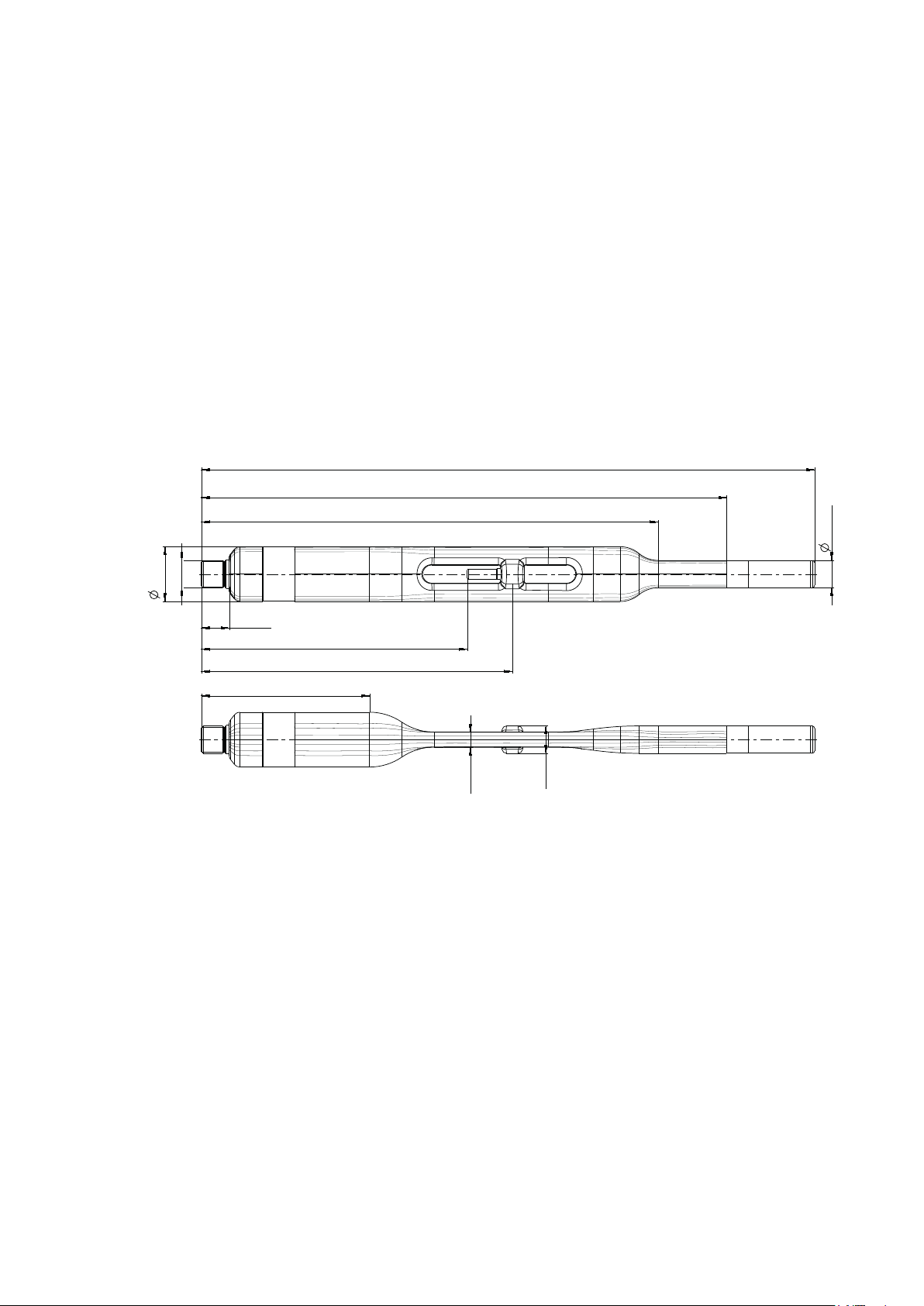
3.2 Dimensions
200
268 (10.6)
230 (9.1)
(7.9)
12 (0.5)
24 (0.94)
M12x1
12 (0.5)
116 (4.6)
136 (5.4)
74 (2.9)
Fig. 1 Dimensions of EE260 in mm (inch)
(0.5)
6.5 (0.3)
12
6
User Manual EE260 Heated Humidity and Temperature Probe for Meteorological Applications
Page 7

Strahlungsschutz mit künstlicher Belüftung HA010511
Radiation shield with artificial ventilation HA010511
E+E Elektronik GmbH
Langwiesen 7
4209 Engerwitzdorf
AUSTRIA
Tel.: +43 7235 605-0
Fax: +43 7235 605-8
info@epluse.com
www.epluse.com
R
Ges.m.b.H.
Ø 150
front view
1
2
3
4
5
6
7
8
1
2
3
4
5
6
7
8
Ø 120
296
488
max. Ø 50
min. Ø 25
142
80
62
Ø 25 (Ø 18...25)
ca. 335
Fig. 2 Dimensions (in mm) of optional radiation shield (ordering code HA010511)
3.3 Electrical Connection
Pin number Function Wire colors for accessories:
1 Analogue output 1 white
2 RS485 B (D-) brown
3 GND analogue output green
4 Analogue output 2 yellow
front view
M12 device plug
Tab. 1 EE260 pin assignment
To meet the EMC Directive 2004/108/EC a shielded connection cable must be used.
The connection cable mentioned above (accessory HA0103xx ,8 pole, M12x1 socket – free ends, PUR
insulation), has a shielding included and is available in several lengths (refer to chapter 6.6).
5 n.c. grey
6 RS485 A (D+) pink
7 Supply voltage blue
8 GND red
- Connection cable HA010322/23/24/25
User Manual EE260 Heated Humidity and Temperature Probe for Meteorological Applications
7
Page 8

4 Installation
4.1 Radiation Shield
With its rotation symmetric design, the EE260 is very well suited for mounting in a radiation shield, thus
protecting the device against rain, snow, ice and solar radiation. The probe is fixed by means of a cable
gland.
Best measurement performance is achieved in the optionally available radiation shield with artificial
ventilation. Please refer to the HA010511 data sheet for more information.
Fig. 3 EE260 mounted within the optional radiation shield HA010511
4.2 Wall Mount/Pole Mount
The probe may be installed on a wall or a pole with the help of the mounting clip HA010227 (not
included in the scope of supply, see data sheet “Accessories”). This also allows a placement in a
Stevenson screen / wheather hut.
Please note:
The probe shall be mounted vertically with the filter cap upside, a proper air circulation around the
probe must be ensured (e.g. with HA010511). Please avoid any improper mechanical stress onto the
probe.
Avoid unnecessary stress here
60 mm (2.4") clamping zone
Fig. 4 EE260 mounted with the optional clip HA010227
8
User Manual EE260 Heated Humidity and Temperature Probe for Meteorological Applications
Page 9

5 Setup and Adjustment
The EE260 is ready to use and does not require any configuration by the user. The factory setup of
EE260 corresponds to the type number ordered. Please refer to the data sheet at www.epluse.com/
EE260. The user can change the factory setup with the help the EE-PCS Product Configuration Software,
the Modbus configuration adapter (order code HA011018) and the EE260 conguration cable (order
code HA011020).
Besides the measurand selection of the analogue and digital outputs and their scaling, the digital
interface settings may be changed. The RH and T measurement is offset and 2-point adjustable. It is
possible to enable or disable the sensing element and the probe heating (separated from each other;
factory setting for both: enabled) and the NAMUR error indication (factory setting: disabled). For the
purpose of pressure compensation, the barometric air pressure at the operating site may be set.
Please note: The EE260 may not be connected to any additional power supply when using the Modbus
configuration adapter HA011018.
HA011018 HA011020
PC
Fig. 5 Configuration
5.1 EE-PCS Product Configuration Software
To use the software for performing adjustments and changes in settings, please proceed as follows:
1. Download the EE-PCS Product Configuration Software from www.epluse.com/configurator and
install it on the PC.
2. Connect the EE260 to the PC using the Modbus configuration adapter and the EE260 configuration
cable.
3. Start the EE-PCS software.
4. Follow the instructions on the EE-PCS opening page for scanning the ports and identifying the
connected device.
5. Click on the desired setup or adjustment mode from the main EE-PCS menu on the left and follow
the online instructions of the EE-PCS
5.2 Digital Interface RS485 with Modbus RTU Protocol
Item Factory settings Selectable values (via EE-PCS)
Baud rate 9 600 9 600, 19 200, 38 400, 57 600, 76 800, 115 200
Data bits 8 8
Parity Even None, odd, even
Stop bits 1 1, 2
Slave address 235 1...247
Tab. 2 Digital interface default settings
The recommended settings for multiple devices in a Modbus RTU network are 9600, 8, even, 1.
The EE260 represents 1 unit load on an RS485 network.
Device address, baud rate, parity and stop bits can be set via:
1. EE-PCS Product Configuration Software, the Modbus configuration adapter HA011018 and the
EE260 configuration cable HA011020.
The EE-PCS can be downloaded free of charge from www.epluse.com/configurator
2. Modbus protocol in the register 60001 (0x00) and 60002 (0x01).
See Modbus Application Note AN0103 (available at www.epluse.com/EE260)
The serial number as ASCII-code is located in the register addresses 0x00...0x07 (16 bits per address).
The firmware version is located in the register address 0x08 (bits 15...8 = major release; bits 7...0 =
minor release). The sensor name is located in register address 0x09. The beforementioned registers can
be read out with function code 0x03 or 0x04.
User Manual EE260 Heated Humidity and Temperature Probe for Meteorological Applications
9
Page 10

Please note: When reading the serial number or the sensor name, it is always necessary to read all 8
registers, even if the desired information requires less.
Please note: For obtaining the correct floating point values, both registers have to be read within
the same reading cycle. The measured value can change between two Modbus requests, therefore,
exponent and mantissa may get inconsistent.
Communication settings (INTEGER 16 bit)
Parameter Register number
Write register: function code 0x06
Slave ID (Modbus address) 1 0x00
Modbus protocol settings
1) Register number starts from 1.
2) Protocol address starts from 0.
3) For Modbus protocol settings see Application Note Modbus AN0103 (available at www.epluse.com/EE260).
3)
INFO (read register)
Parameter Register number
Read register: function code 0x03 / 0x04
Serial number (as ASCII) 1 0x00
Firmware version 9 0x08
Sensor Name 10 0x09
1) Register number starts from 1.
2) Protocol address starts from 0.
1)
[DEC] Protocol address2) [HEX]
2 0x01
1)
[DEC] Protocol address2) [HEX]
Air pressure
Parameter Register number
1)
[DEC] Register address2) [HEX]
Read and write register: function code 0x03 / 0x10
Air pressure
1) Register number starts from 1
2) Register address starts from 0
3) Ambient pressure in mbar, with 2 decimal digits (e.g. 1 008.25), default value 1 013.25 mbar
3)
5001 0x1388
10
User Manual EE260 Heated Humidity and Temperature Probe for Meteorological Applications
Page 11

5.3 Modbus Register Map
The measured data is saved as a 32 bit floating point values (data type FLOAT) and as 16 bit signed
integer values (data type INTEGER).
FLOAT 32 bit:
Parameter Unit Register number
Read register: function code 0x03 / 0x04
Temperature T
Relative humidity RH, Uw % RH 1021 0x3FC
Water vapour partial pressure e
Dew point temperature Td
Wet bulb temperature Tw
Absolute humidity dv
Mixing ratio r
Specific enthalpy h
Frost point temperature Tf
Volume concentration Wv
Saturation vapor pressure
above water ew
Saturation vapor pressure
above ice ei
Ice bulb temperature Ti
Specific humidity qv
1) Register number starts from 1
2) Register address starts from 0
1)
[Dec] Register address
°C 1003 0x3EA
°F 1005 0x3EC
°K 1009 0x3F0
mbar 1101 0x44C
psi 1103 0x44E
°C 1105 0x450
°F 1107 0x452
°K 1147 0x47A
°C 1109 0x454
°F 1111 0x456
°K 1145 0x478
g/m³ 111 3 0x458
gr/ft³ 1115 0x45A
g/kg 1121 0x460
gr/lb 1123 0x462
kJ/kg 1125 0x464
ft lbf/lb 1127 0x466
BTU/lb 1129 0x468
°C 1131 0x46A
°F 1133 0x46C
°K 1149 0x47C
ppm 1151 0x47E
% 1155 0x482
‰ 1157 0x484
mbar 1221 0x4C4
psi 1223 0x4C6
mbar 1225 0x4C8
psi 1227 0x4CA
°C 1237 0x4D4
°F 1239 0x4D6
°K 1241 0x4D8
g/kg 1247 0x4DE
gr/lb 1249 0x4E0
2)
[HEX]
User Manual EE260 Heated Humidity and Temperature Probe for Meteorological Applications
11
Page 12

INTEGER 16 bit:
3)
Parameter Unit Scale
Read register: function code 0x03 / 0x04
°C 100 4002 0xFA1
Temperature T
Relative humidity RH, Uw % RH 100 4011 0xFAA
Water vapour partial pressure e
Dew point temperature Td
Wet bulb temperature Tw
Absolute humidity dv
Mixing ratio r
Specific enthalpy h
Frost point temperature Tf
Volume concentration Wv
Saturation vapor pressure
above water ew
Saturation vapor pressure
above ice ei
Ice bulb temperature Ti
Specific humidity qv
1) Register number starts from 1
2) Register address starts from 0
3) Examples: For scale 100, the reading of 2550 means a value of 25.5. For scale 50, the reading of 2550 means a value of 51.
°F 50 4003 0xFA2
°K 50 4005 0xFA4
mbar 10 4051 0xFD2
psi 1000 4052 0xFD3
°C 100 4053 0xFD4
°F 100 4054 0xFD5
°K 100 4074 0xFE9
°C 100 4055 0xFD6
°F 100 4056 0xFD7
°K 100 4073 0xFE8
g/m³ 10 4057 0xFD8
gr/ft³ 10 4058 0xFD9
g/kg 10 4061 0xFDC
gr/lb 10 4062 0xFDD
kJ/kg 1 4063 0xFDE
ft lbf/lb 1 4064 0xFDF
BTU/lb 1 4065 0xFE0
°C 100 4066 0xFE1
°F 100 4067 0xFE2
°K 100 4075 0xFEA
ppm 0.1 4076 0xFEB
% 1000 4078 0xFED
‰ 100 4079 0xFEE
mbar 100 4111 0x100E
psi 100 4112 0x100F
mbar 100 4113 0x1010
psi 100 4114 0x1011
°C 100 4119 0x1016
°F 100 4120 0x1017
°K 50 4121 0x1018
g/kg 10 4124 0x101B
gr/lb 10 4125 0x101C
Register number1) [Dec] Register address
2)
[HEX]
5.4 Modbus Message Example
Example of Modbus RTU command for reading the temperature (float value) T = 24.625015 °C
from the register 0x3EA
Device EE260; slave ID 235 [0xEB]
Reference document, chapter 6.3: www.modbus.org/docs/Modbus_Application_Protocol_V1_1b3.pdf
See Application Note Modbus AN0103 (available on www.epluse.com/EE260)
Modbus ID
address
Request [Hex]: EB 03 03 EA 00 02 F3 71
Modbus ID
address
Response Hex]: EB 03 04 00 08 41 C5 C0 3C
12
Function
code
Function
code
User Manual EE260 Heated Humidity and Temperature Probe for Meteorological Applications
Starting
address Hi
Byte
count
address Lo
Register 1
value Hi
Starting
Register 1
value Lo
No. of
register Hi
Register 2
value Hi
No. of
register Lo
Register 2
value Lo
CRC
CRC
Page 13

Decoding of oating point values:
Floating point values are stored according IEEE754 standard. The byte pairs 1, 2 and 3, 4 are inverted
as follows:
MMMMMMMM MMMMMMMM SEEEEEEE EMMMMMMM
Byte 3 Byte 4 Byte 1 Byte 2
Example:
Response [Hex] Value in decimal
Byte 1 (Register 2 - Hi) Byte 2 (Register 2 – Lo) Byte 3 (Register 1 - Hi) Byte 4 (Register 1 - Lo)
44
C5 00 08 24.625015
6 Maintenance and Service
EE260 does not require any special maintenance, nevertheless for high accurate measurements
especially over wide RH and T ranges it is recommended to calibrate the probe every 12 months. If
needed, the enclosure may be cleaned and the device may be re-adjusted as described below.
6.1 Cleaning
Use a damp soft cloth to remove deposits of dust or dirt from the exterior of the probe. Do not use any
solvents or abrasive cleaning agents and no isopropanol (isopropyl alcohol).
In case of dusty, oily and polluted environment:
Use a damp soft cloth to remove deposits of dust or dirt from the exterior of the probe. Do not use
any solvents or abrasive cleaning agents.
The filter cap shall be replaced once in a while with an E+E original one (see below).
If needed, the sensing element of the humidity probe can be cleaned by the user (see the E+E
cleaning instructions)
6.2 Filter Replacement
In a dusty or polluted environment it might be necessary to replace the filter cap or the filter membrane,
respectively, once in a while. In most of the cases, a clogged filter shows visible contamination or dirt.
Longer response time of the humidity measurement also indicates a clogged filter cap. In such cases,
replace the filter cap or the filter membrane by a new, original one, see chapter „6.6 Spare Parts“.
Procedure
Turn the filter cap counter-clockwise for removing it.
Install the new filter cap finger tight by turning it clockwise.
While replacing the filter cap take very good care to not touch or rub the sensing element.
6.3 Repairs
Repairs may be carried out by the manufacturer only. The attempt of unauthorized repair excludes any
warranty claims.
6.4 RH / T Adjustment and Calibration
In meteorological applications there might arise the need for periodical humidity and temperature
calibration or adjustment.
Definitions
Calibration documents the accuracy of a measurement device. The device under test (specimen) is
compared with the reference and the deviations are documented in a calibration certificate. During
the calibration, the specimen is not changed or improved in any way.
Adjustment improves the measurement accuracy of a device. The specimen is compared with the
reference and brought in line with it. An adjustment can be followed by a calibration which documents
the accuracy of the adjusted specimen.
User Manual EE260 Heated Humidity and Temperature Probe for Meteorological Applications
13
Page 14

6.4.1 Calibration and Adjustment at E+E Elektronik
Calibration and/or adjustment can be performed in the E+E Elektronik calibration laboratory. For
information on the E+E capabilities in ISO or accredited calibration please see www.eplusecal.com.
6.4.2 Humidity Calibration and Adjustment by the User
Depending on the level of accuracy required, the humidity reference can be:
Handheld device (e.g. Omniport 30), please see www.epluse.com/omniport30.
Humidity standards (e.g. Humidity Calibration Kit), please see www.epluse.com/EE260.
Please note: It is of very high importance that for the RH calibration the RH and T sensing elements
are at the same temperature.
Please contact your sales representative for assistance.
Please note: When the calibration/adjustment procedure with the help of EE PCS starts, both heating
modes of the EE260 are disabled automatically if they have on status. At the end of the procedure the
heating comes back to on automatically.
14
Fig. 6 Setting the Heating Mode in E+E Configurator
Please observe these important notes on changing the sensing element data:
■ The sensing element data generally only has informational character.
■ For all applications, an alleged drift of the device can be corrected using the offset correction or the
one/two point adjustment offered by the EE-PCS.
■ For very special requirements, the drift can be corrected acting upon the characteristic of the sensing
elements, i.e. upon the sensor data such as nominal capacity or humidity coefficient. This requires
deep knowledge about the sensing elements and the design of the measuring device.
User Manual EE260 Heated Humidity and Temperature Probe for Meteorological Applications
Page 15

■ Important! Contact the E+E sales representative before any attempt of acting upon the sensing
element data!
■ Caution! Upon changing the sensing element data, the original data is lost. There is no way to
automatically return to the original sensor data. Please make sure to note and save the original
sensing element data before making any change!
6.4.3 Temperature Calibration and Adjustment by the User
For a reproducible T calibration or adjustment, it is recommended to measure the Pt100 of the EE260
in a liquid bath. This reduces the T inhomogeneity surrounding the probe to a minimum. It must be
ensured to use an inert, nonconductive liquid which does not chemically contaminate the sensor
element (e.g. GALDEN HT200).
Please note: When the calibration/adjustment procedure with the help of EE PCS starts, both heating
modes of the EE260 are disabled automatically if they have on status. At the end of the procedure the
heating comes back to on automatically.
The temperature reference (T-Ref) shall be located at the same level as the Pt100 of the EE260.
T-Ref
Fig. 7 Temperature calibration/adjustment in a liquid bath
PC
Pt100
Mounting clip HA0102277
EE-PCS
6.5 Error Indication on the Analogue Output (NAMUR)
The EE260 features an error indication on its analogue outputs according to the NAMUR NE 043
recommendations (Standardization of the Signal Level for the Failure Information of Digital Transmitters,
Edition 2003-02-03, see www.namur.net/en/recommendations-and-worksheets/current-nena.html).
The feature is enabled by factory default and can be disabled with the EE-PCS Product Configuration
Software, see above.
Output signal NAMUR signal level
0-1 V 1.1 V
0-2.5 V 2.75 V
0-5 V 5.5 V
0-10 V 11 V
6.6 Spare Parts
Description Order code
Filter PTFE membrane on stainless steel body HA010114
PTFE membrane for filter HA010114ME
User Manual EE260 Heated Humidity and Temperature Probe for Meteorological Applications
15
Page 16

7 Accessories
Please also refer to the “Accessories“ data sheet.
Description Order code
Radiation shield, articially ventilated HA010511
Modbus configuration adapter1) HA011018
EE260 conguration cable1) HA011020
E+E Product Configuration Software (Download: www.epluse.com/configurator) EE-PCS
M12x1 cable connector, 8 pole socket HA010704
Connection cable, 8 pole, M12x1 socket - free ends
1.5 m (4.9 ft) HA010322
3 m (9.8 ft) HA010323
5 m (16.4 ft) HA010324
10 m (32.8 ft) HA010325
Wall mounting clip Ø25 mm HA010227
Protection cap M12 female connector HA010781
Protection cap M12 male connector HA010782
1) Both accessories are necessary for conguration
16
User Manual EE260 Heated Humidity and Temperature Probe for Meteorological Applications
Page 17

8 Technical Data
Measurands
Relative humidity
Measuring range 0…100 % RH
Sensing element E+E HMC01, heated
Response time t
Accuracy
1)
-15...40 °C
-15...40 °C (5…104 °F) for RH > 90 % ± 2.0 % RH
-25...60 °C
-40...-25 °C
Temperature
Measuring range -60...60 °C
Temperature sensor Pt100 1/3 DIN B
Accuracy
0.6
0.5
0.45
0.4
0.3
0.2
0.15
0.1
0
-60 -50 -10-20-30-40 100 605020 30 40
Outputs
Analogue 0 - 1 V / 0 - 2.5 V / 0 - 5 V / 0 - 10 V
Freely selectable and scalable 0 < I
Digital interface RS485 (EE260 = 1 unit load)
Protocol Modbus RTU
Default settings Baud rate 9
General
Supply voltage 7 - 30 V DC
Power consumption, typ. 300 mW (25 mA @ 12 V DC, heating included)
Electrical connection M12x1, 8 poles, stainless steel 1.4404
Filter PTFE membrane, stainless steel body
Protection class IP67
Enclosure material Thermoplastic elastomer, UV resistant and T stable
Electromagnetic compatibility
at 20 °C (68 °F) < 15 s
90
(incl. hysteresis, non-linearity and repeatability)
(5…104 °F) for RH ≤ 90 % ± (1.3 + 0.3 % *mv) % RH mv = measured value
(-13…140 °F) ± (1.4 + 1 % *mv) % RH
(-40…-13 °F) ± (1.5 + 1.5 % *mv) % RH
2)
(-76...140 °F)
Analogue output
0.4
0.3
0.2
0.1
0
-60 -50 -10-20-30-40 100 605020 30 40
< 1 mA
L
600
4)
EN 61326-1 EN 61326-2-3
RS485 interface
3)
, parity even, stop bits 1, slave ID 235
Operating and -60...60 °C
(-40...140 °F)
storage conditions 0...100 % RH (operation)
0...95 % RH non-condensing (storage)
1) The accuracy statement includes the uncertainty of the factory calibration with an enhancement factor k=2 (2-times standard deviation). The accuracy was
calculated in accordance with EA-4/02 and with regard to GUM (Guide to the Expression of Uncertainty in Measurement).
2) The EE260 simultaneously features two analogue voltage outputs and the RS485 interface.
3) Supported baud rates: 9 600, 19 200, 38 400, 57 600, 76 800 and 115 200; find more details about communication setting in the User Manual and the Modbus
Application Note at www.epluse.com/ee260
4) Compliance with EN61000-4-3 and EN 610004-6: Electromagnetic interferencees may cause additional deviations <2 % RH.
User Manual EE260 Heated Humidity and Temperature Probe for Meteorological Applications
17
Page 18

HEADQUARTERS
E+E Elektronik Ges.m.b.H.
Langwiesen 7
4209 Engerwitzdorf
Austria
Tel.: +43 7235 605-0
E-mail: info@epluse.com
Web: www.epluse.com
SUBSIDIARIES
E+E Elektronik China
18F, Kaidi Financial Building,
No.1088 XiangYin Road
200433 Shanghai
Tel.: +86 21 6117 6129
E-mail: info@epluse.cn
E+E Elektronik France
Le Norly III, 136 chemin du Moulin
69130 Ecully
Tel.: +33 4 74 72 35 82
E-mail: info@epluse.fr
E+E Elektronik Germany
Schöne Aussicht 8 C
61348 Bad Homburg
Tel.: +49 6172 13881-0
E-mail: info@epluse.de
E+E Elektronik Italy
Via Alghero 17/19
20128 Milano (MI)
Tel.: +39 02 2707 86 36
E-mail: info@epluse.it
E+E Elektronik Korea
Suite 2001, Heungdeok IT
Valley Towerdong, 13,
Heungdeok 1-ro, Giheung-gu
16954 Yongin-si, Gyeonggi-do
Tel.: +82 31 732 6050
E-mail: info@epluse.co.kr
E+E Elektronik USA
333 East State Parkway
Schaumburg, IL 60173
Tel.: +1 847 490 0520
E-mail: office@epluse.com
 Loading...