

Page 1
QUICK GUIDE
0 0 0 0 0 0 0 0
0
1 1 0 1 0 0 0 0
0
EE211 - Humidity and Temperature Sensor for Continuous High Humidity
(Full User Guide at www.epluse.com/EE211)
Assembly and Installation
• Insert the M20 cable gland included in the scope of supply into the corresponding opening of the EE211 basis unit and x it tight
with the nut.
• Install the EE07-MT temperature probe either directly onto the M12 connector of the EE211 basis unit or using the optional
probe cable.
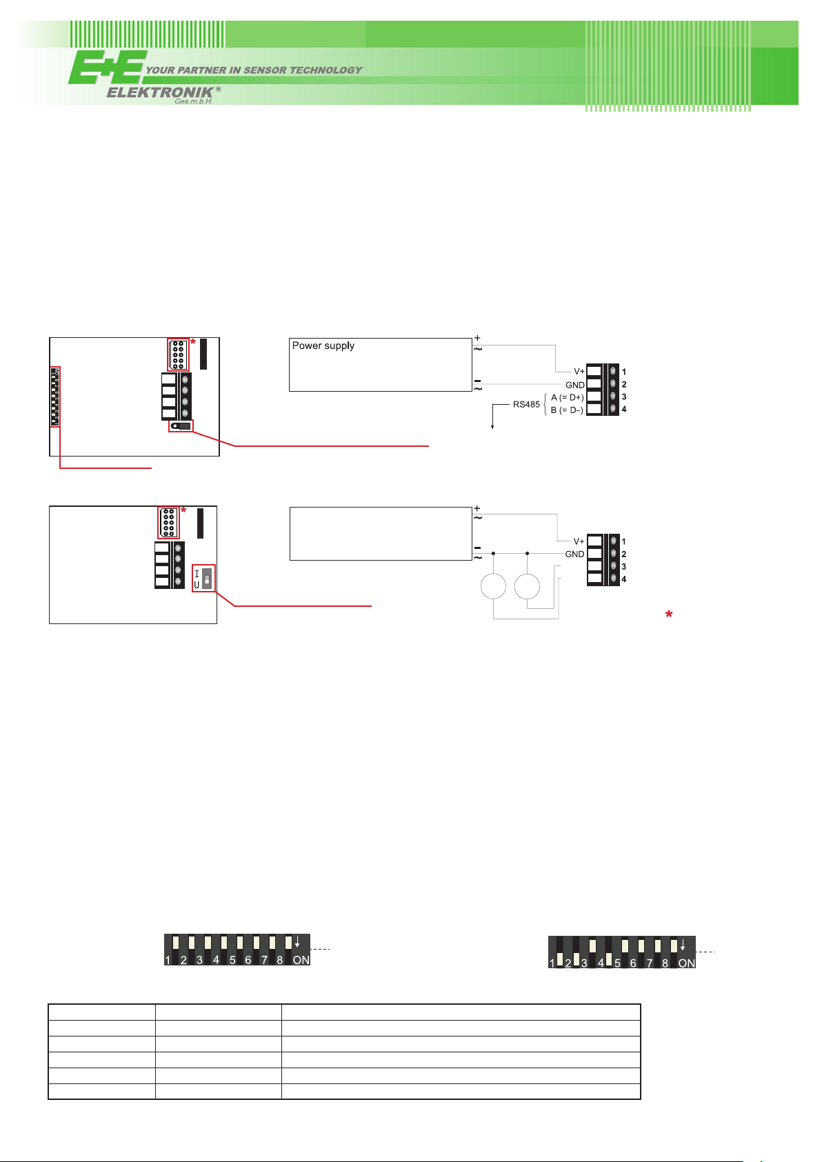
Connection Diagram
EE211-M1J3 - Digital Output
15...35 V DC
24 V AC ± 20%
Output:
Modbus RTU
Bus termination resistor 120 Ω (jumper)
Address switches
EE211-M1A2/3/5/6 - Analogue Output
15...35 V DC
24 V AC ± 20%
OUT1
OUT2
V
V
mA
mA
Setup interface
Selection output signal U / I
Output: 0...5 V
0...10 V
0...20 mA
4...20 mA
Analogue Settings
Selection Output Signal Voltage / Current
The factory setup of the output signal and scaling corresponds to the type number as ordered.
The output signal voltage (U) or current 3-wire (I) can be selected with the DIP switch on the main electronics board (see
Connection Diagram - EE211-M1A2/3/5/6). This does not impact on the scaling of the outputs, which can be changed using the
EE-PCS Product Configuration Software and the optional USB configuration adapter HA011066.
Digital Settings - RS485 Interface with Modbus RTU Protocol
Hardware Bus Termination
If required, the bus termination shall be realized with 120 Ohm resistor, jumper on the board.
Jumper mounted = bus terminated
Jumper not mounted = bus not terminated
Address setting via EE-PCS Product Configuration Software
All DIP switches at position 0 → address has to be set via
Product Configuration Software
Factory setting: 239 (permitted values: 1…247).
Example: Slave address is set via configuration software.
Address Switch:
1
Address setting via DIP switch
Setting the DIP switches to any other address than 0,
overrules the slave address set via configuration software
(permitted values: 1…247).
Example: Slave address set to 11 (= 0000 1011 binary).
Address Switch:
1
Digital Settings
Factory settings Selectable values
Baud rate 9600 9600, 19200, 38400, 57600, 76800, 115200
Data bits 8 8
Parity EVEN None, odd, even
Stop bits 1 1 or 2
Slave address 239 1...247
For details how to set the ID address, baud rate, parity and stop bits, please see Full User Guide at www.epluse.com/EE211.
Page 2

Modbus Register Map
FLOAT 32 bit (read register):
Function code /
Register number
30026 0x19 temperature [°C], [°F]
30028 0x1B relative humidity [%]
30030 0x1D water vapour partial pressure [mbar], [psi]
30032 0x1F dew point temperature [°C], [°F]
30034 0x21 wet bulb temperature [°C], [°F]
30036 0x23 absolute humidity [g/m³], [g/ft³]
30038 0x25 mixing ratio [g/kg], [gr/lb]
30040 0x27 specic enthalpy [kJ/kg], [BTU/lb]
30042 0x29 frost point temperature [°C], [°F]
INTEGER 16 bit (read register):
Function code /
Register number
30301 0x12C temperature [°C], [°F] 100
30302 0x12D relative humidity [%] 100
30303 0x12E water vapour partial pressure [mbar], [psi] 100
30304 0x12F dew point temperature [°C], [°F] 100
30305 0x130 wet bulb temperature [°C], [°F] 100
30306 0x131 absolute humidity [g/m³], [g/ft³] 100
30307 0x132 mixing ratio [g/kg], [gr/lb] 100
30308 0x133 specic enthalpy [kJ/kg], [BTU/lb] 100
30309 0x134 frost point temperature [°C], [°F] 100
1)
[Dec]
1)
[Dec]
Register address2) [Hex] Parameter name Unit
Register address2) [Hex] Parameter name Unit
3)
3)
Scale
4)
INTEGER 16 bit (read and write register):
Function code / Register number
60001 0x00 Slave-ID
60002 0x01 Modbus protocol settings
INFO (read register):
Function code / Register number
30001 0x00 Serial number (as ASCII)
30009 0x01 Firmware version
30010 0x09 Sensor name
1) Register number starts from 1
2) Register address starts from 0
3) The choice of measurement units (metric or non-metric) must be done in the ordering guide, see EE211 data sheet.
Switching from metric to non-metric or vice versa by using the EE-PCS is not possible.
4) 100 is scale 1:100 (2550 is equivalent to 25.5 °C)
5) If the ID is set via DIP-switch the response will be NAK
6) For Modbus protocol settings please see Application Note Modbus AN0103 (available on www.epluse.com/EE211)
1)
[Dec] Register address2) [Hex] Parameter name
1)
[Dec] Register address2) [Hex] Parameter name
5)
modbus address
6)
USA
FCC notice:
This equipment has been tested and found to comply with the limits for a Class B digital device, pursuant to part 15 of the FCC Rules. These limits are
designed to provide reasonable protection against harmful interference in a residential installation. This equipment generates, uses and can radiate radio
frequency energy and, if not installed and used in accordance with the installation manual, may cause harmful interference to radio communications.
However, there is no guarantee that interference will not occur in a particular installation. If this equipment does cause harmful interference to radio or
television reception, which can be determined by turning the equipment off and on, the user is encouraged to try to correct the interference by one or
more of the following measures:
- Reorient or relocate the receiving antenna.
- Increase the separation between the equipment and receiver.
- Connect the equipment into an outlet on a circuit different from that to which thereceiver is connected.
- Consult the dealer or an experienced radio/TV technician for help.
CANADIAN
ICES-003 Issue 5:
CAN ICES-3 B / NMB-3 B
INFORMATION
Langwiesen 7 • A-4209 Engerwitzdorf
Tel: +43 7235 605-0 • Fax: +43 7235 605-8
info@epluse.com • www.epluse.com
LG Linz Fn 165761 t • UID-Nr. ATU44043101
Place of Jurisdiction: A-4020 Linz • DVR0962759
+43 7235 605 0 / info@epluse.com
BA_EE211_QGMS_e // v1.1 // Modification rights reserved // 350182
 Loading...