

Page 1
USER‘S GUIDE
EE210 - Humidity and Temperature Transmitter for
demanding Climate Control Applications
GENERAL
The EE210 transmitter, available for wall or duct mounting as well as with remote probe, is designed for highly accurate
measurement of humidity and temperature in demanding climate control applications. The EE210 incorporates the E+E humidity and
temperature sensor HCT01.
For use in special applications do not hesitate to contact E+E Elektronik or a local distributor.
CAUTION
• For accurate measurement it is essential that the temperature of the sensing probe and mainly of the sensing head is same as
the temperature of the air to measure. Avoid mounting the transmitter in a way which creates temperature gradients along the
probe.
• The transmitter and mainly the sensing head shall not be exposed to extreme mechanical stress.
• The transmitter must be operated with the filter cap on at all times. Do not touch the sensors inside the sensing head.
• While replacing the filter cap (because of pollution for instance) against an original spare one please take very good care to
not touch the sensors.
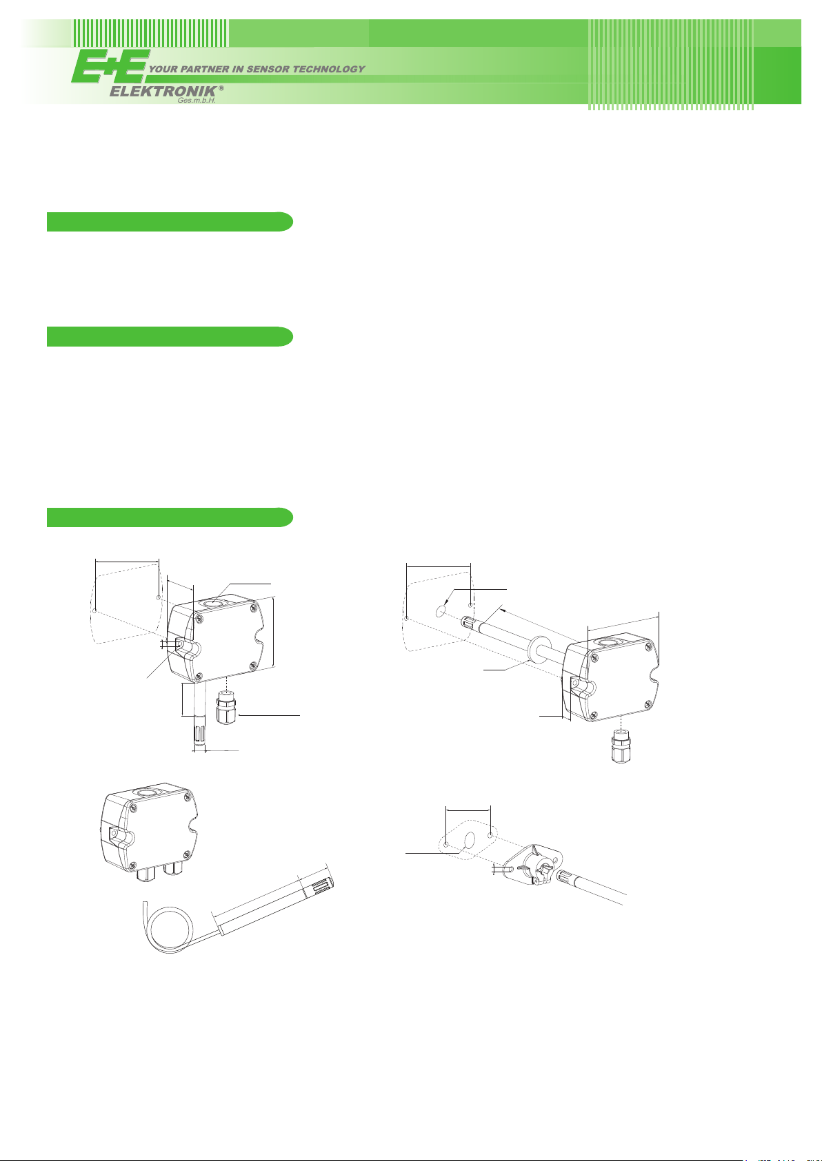
DIMENSIONS / MOUNTING
Type A
±0.3
mm
90
±0.11
3.54
“
5mm
0.2“
Recommended mounting screws:
ST4.2x50 DIN7981C
Type C
46mm
1.81“
~2.16“
~55mm
FOR CONDUIT
INSTALLATION
CABLE GLAND M16x1.5
Ø 12mm
Ø 0.47“
EE210P
106mm
4.17“
3.17“
80.6mm
34mm
1.34“
Type B
Ø > 16mm
Ø > 0.63“
90
3.54
±0.3
mm
±0.11
“
Ø > 13mm
Ø > 0.51“
60
2.36
~205mm
~8.07“
GASKET
19mm
0.75“
±0.3
mm
±0.11
“
6mm
0.24“
101mm
3.98“
EE210 with cable gland: Use a matching wrench to install the cable gland (in the scope of supply) onto the EE210 enclosure.
EE210 with conduit connection for the North American market: use a flat screwdriver to knock open the blind, carefully, in order
to avoid damaging the electronics inside the enclosure. The conduit adapter is not included in the scope of supply. The M16x1.5
opening for the cable gland shall be tightly closed using the blind plug included in the scope of supply.
Page 2
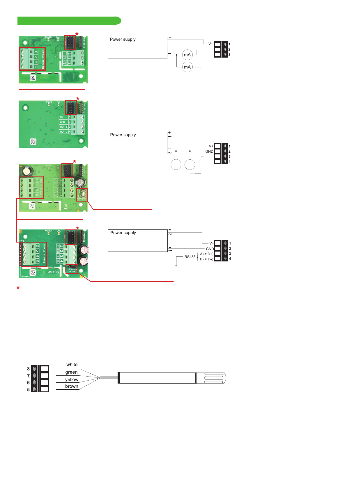
CONNECTION DIAGRAM
EE210-HT6 EE210-HT6
ONLY FOR REMOTE PROBE!
EE210-HT3
EE210-HT2/3/5
20...30 V DC RL<500 Ohm
11...30 V DC R
Important: The EE210-HT6 (4...20 mA, two-wire) with display operates correctly only if both outputs are connected.
<50 Ohm
L
Output: 4-20 mA
OUT1
OUT2
EE210-HT2/3/5
15...35 V DC
24 V AC ±20 %
OUT1
Output: 0-5 V
0-10 V
0-20 mA
V
mA
mA
OUT2
V
Selection ouput signal U / I
ONLY FOR REMOTE PROBE!
EE210-HTx3 EE210-HTx3
15...35 V DC
24 V AC ±20 %
Output:
Modbus RTU or
BACnet MS/TP
Bus termination resistor 120 Ω (jumper)
con guration connector
EE210P (type C)
The EE210P remote probe for EE210-HTxxPC shall be ordered and it is supplied as separate item. EE210P is to be connected to the
EE210 by the user.
• Install first the cable gland (included in EE210 scope of supply) onto the EE210 enclosure.
• Before connecting the probe, disconnect the EE210 power supply.
• Insert the EE210P cable through the cable gland and connect it to the screw terminals according to the connection diagram
below.
Please note:
EE210P is an intelligent probe with digital output and as such it is interchangeable. In case the probe or its cable gets destroyed or if a
longer cable is needed, please order a replacement probe according to EE210 data sheet. The replacement probe shall be installed as
described above.
Important:
Make sure that the cable glands are closed tightly for both EE210P probe cable and for the power supply and outputs cable. This is
necessary for assuring the protection class (IP class) of the enclosure according to EE210 speci cation, as well as for stress relief at
the screw terminals on the EE210 board.
Page 3

LED INDICATION
Green LED - information during normal operation:
Blue LED - information during setup with the optional
E+E Product Con guration Adapter (EE-PCA):
on = everything OK
fl ashing = the main board does not recognize the
measurement electronics inside the sensing probe
on = EE-PCA is powered, no communication in progess
fl ashing = EE-PCA powered, communication in progress
off = EE-PCA not connected to the EE210
off = no power supply or main board failure
DISPLAY
Factory Setup:
The display shows the two parameters selected for output 1 and output 2 (according to ordering
code). For digital output versions the display shows RH and T.
User Setup:
The user can change the display layout to 1, 2 or 3 lines and select the
parameters to be displayed by using EE-PCS Product Configuration Software (free download
from www.epluse.com/configurator) and the optional EE-PCA Product Configuration Adapter (not
included in the scope of supply).
Important: The EE210-HT6 (4...20 mA, two-wire version) with display operates correctly only if
both outputs are connected.
SELECTION OUTPUT SIGNAL U/I
The factory setup of the output signal and scaling corresponds to the type number as ordered.
The output signal (voltage or current 3-wire) can be selected with the DIP switch on the main electronics board (see picture PCB
EE210-HT2/3/5). This does not impact on the scaling of the outputs, which can be changed using EE-PCA and EE-PCS.
Examples
Factory setup: voltage output 0-5 V or 0-10 V corresponds to 0…100% RH.
After switching from U to I: current output 0…20 mA corresponds to 0…100% RH.
A change of the current output range for instance to 4-20 mA (3-wire) can be made subsequently with the EE-PCA and EE-PCS.
Factory setup: current output 0-20 mA corresponds to -10…50 °C.
After switching from I to U: voltage output 0-10 V corresponds to -10…50 °C.
A change of the voltage output range for instance to 0-5 V can be made subsequently with the EE-PCA and EE-PCS.
SCOPE OF SUPPLY
Model
EE210 according ordering guide
Cable gland
Mounting materials
Mounting fl ange
EE210
Wall mount
(Type A)
EE210
Duct mount
(Type B)
EE210
Remote version
(Type C)*
(2 pcs.)
EE210-P
Remote probe* for
Type C
Additionally for all
EE210 with RS485
interface
Inspection certificate according
to DIN EN10204 - 3.1
Quick Guide EE210 RS485 Setup
* EE210-P is not included in the Scope of Supply of the EE210 Type C
Page 4

DIGITAL SETTINGS
Address Setting
Address Switch
0 0 0 0 0 0 0 0
Slave address setting via EE-PCS Product Conguration Software:
0
All Dip-Switches at position 0 → address has to be set via Product Conguration Software
(factory setting: Modbus...242 / BACnet...1).
1
Example: Slave address is set via conguration software.
Address Switch
Slave address setting via Dip-Switch:
0
Setting the Dip-Switch to any other address than 0 overwrites the slave address set
via conguration software.
1
1 1 0 1 0 0 0 0
Example: Slave address set to 11 (=00001011 binary).
BACnet Setup
BACnet PICS are abvailable for download at www.epluse.com/EE210
Modbus Setup
The measured values are saved as a 32 Bit float value from 0x19 to 0x1F and from 0x23 to 0x29. Additionally the measured values
are available as 16 Bit signed integer from 0x12C to 0x12F and from 0x131 to 0x134.
The factory setting for the Slave-ID (Modbus address) is 242 as an integer 16Bit value. This ID can be changed by the user in the
register 60001 (0x00), permitted values are 1 - 247 permitted.
The serial number as ASCII-code is located at register address 30001-30008 (16 Bit per address).
The Firmware version is located at register address 30009 (Bit 15...8 = major release; Bit 7...0 = minor release).
The choice of measurement units (metric or not metric) must be done in the ordering guide, see EE210 data sheet.
Switching from metric to non metric or vice versa by using the EE-PCS is not possible.
FLOAT (read register):
Register
address
30026 0x19 temperature [°C], [°F]
30028 0x1B relative humidity [%]
30030 0x1D water vapour partial pressure [mbar], [psi]
30032 0x1F dew point temperature [°C], [°F]
30036 0x23 absolute humidity [g/m³], [g/ft³]
30038 0x25 mixing ratio [g/kg], [gr/lb]
30040 0x27 specic enthalpy [kJ/kg], [BTU/lb]
30042 0x29 frost point temperature [°C], [°F]
Communication
address
Parameter
name
INTEGER (read register):*
Register
address
30301 0x12C temperature [°C], [°F]
30302 0x12D relative humidity [%]
30303 0x12E water vapour partial pressure [mbar], [psi]
30304 0x12F dew point temperature [°C], [°F]
30306 0x131 absolute humidity [g/m³], [g/ft³]
30307 0x132 mixing ratio [g/kg], [gr/lb]
30308 0x133 specic enthalpy [kJ/kg], [BTU/lb]
30309 0x134 frost point temperature [°C], [°F]
* Values are stored with a scaling of 1:100 (e.g.: 2550 is equivalent to 25.5°C)
Communication
address
Parameter
name
INFO (read register):
Register
address
30001 0x00 Serial number (as ASCII)
30009 0x08 Firmware version
Communication
address
Parameter
name
INTEGER (write register):*
Register
address
60001 0x00 Slave-ID (modbus addresse)
60002 0x01 Modbus protocol settings*
*For Modbus protocol setting please see Application Note Modbus
(www.epluse.com/EE210)
Communication
address
Parameter
name
Protocol setting:
Address, baudrate, parity and stop bits can be set via:
1. Product Congurator Software (available on www.epluse.com/EE210)
2. Modbus protocol (please see Application Note Modbus (available on www.epluse.com/EE210)
TECHNICAL DATA
(Modification rights reserved)
Measured Values
Relative Humidity (RH)
Sensor E+E Sensor HCT01-00D
Working range 0...100 % RH
RH accuracy (incl. hysteresis, non-linearity and repeatability)
Wall & duct version:
-15...40 °C (5...104 °F) ≤90 % RH ±(1.3 + 0.003*measured value) % RH
-15...40 °C (5...104 °F) >90 % RH ± 2.3 % RH
-40...60 °C (-40...140 °F) ±(1.5 + 0.015*measured value) % RH
Remote probe version
at 20 °C (68 °F) ±2.5 % RH
Page 5

Temperature (T)
Sensor Pt1000 (tolerance class B, DIN EN 60751) integrated in HCT01
T-accuracy wall & duct remote probe
∆ °C
∆ °C
°C
Outputs
Analogue output 0-5 V / 0-10 V -1 mA < I
4-20 mA (2-wire) R
0-20 mA (3-wire) R
Digital output RS485 (BACnet MS/TP or Modbus RTU), max. 32 EE210 in one bus
≤ 500 Ohm
L
≤ 500 Ohm
L
< 1 mA
L
General
Power supply (Class III)
for 4-20 mA, 2-wire 10 V + RL x 20 mA < V+ < 30 V DC
for 0-20 mA, 3-wire
for 0-5 V / 0-10 V / RS485
Current consumption at 24 V
Voltage output DC supply max. 12 mA; with display max. 23 mA
AC supply max. 34 mA
Current output
2-wire DC supply max. 40 mA; with display max. 40 mA
3-wire DC supply typ. 33 mA; with display max. 44 mA
AC supply typ. 65 mA
Digital interface DC supply typ. 5 mA; with display max. 20 mA
AC supply typ. 15 mA
Display 1, 2 or 3 lines, user configurable, optional with backlight
Connection Screw terminals, max. 1.5 mm
Housing material Polycarbonate, UL94V-0 (with Display UL94HB) approved
Protection class IP65 / NEMA 4
Cable gland M16 x 1.5
Probe cable (type C) PVC, Ø 4.3 mm, 4 x 0.25 mm
Sensor protection E+E Coating
Electromagnetic compatibility EN61326-1 EN61326-2-3
Industrial Environment
Temperature ranges Operating: -40...60 °C
Storage: -40...60 °C
Temperature ranges with display Operating: -20...50 °C (-4...122 °F) (-40...80 °C for remote probe EE210P)
Storage: -20...60 °C
1 USA & Canada: class 2 supply required, max. supply voltage 30 V
15-35 V DC
1)
or 24V AC ±20 %
; with display max. 49 mA
rms
; with display max. 84 mA
rms
; with display max. 35 mA
rms
(-40...140 °F) (-40...80 °C for remote probe EE210P)
(-40...140 °F)
(-4...140 °F)
rms
rms
rms
2
2
, Length: 1.5 or 3 m (4.9 or 9.8 ft)
°C
SETUP AND ADJUSTMENT
The EE210 transmitter is ready to use and does not require any con guration by the user. The factory setup of EE210 corresponds to
the type number ordered. (Ordering guide please see data sheet at www.epluse.com/EE210.)
If needed, the user can change the factory setup by using the optional E+E Product Configuration Adapter (EE-PCA) and the E+E
Product Configuration Software (EE-PCS).
HA011050 EE210 V03
HA011062
(optional)
PC
One can assign other physical quantities to the analogue outputs, change the scaling of the outputs, set the display and perform one or
two point adjustment for humidity and temperature.
For con guration with EE-PCA and EE-PCS both 4-20 mA two-wire outputs must be connected.
For product data sheets EE-PCS and EE-PCA please see www.epluse.com.
The E+E Product Configuration Software (EE-PCS) is free and can be downloaded from www.epluse.com/ee-configurator.
Page 6

MAINTENANCE
Humidity calibration and adjustment:
Depending on the application and the requirements of certain industries, there might arise the need for periodical humidity calibration
(comparison with a reference) or adjustment (bringing the device in line with a reference).
• Calibration and adjustment at E+E Elektronik
Calibration and/or adjustment can be performed in the E+E Elektronik calibration laboratory. For information on the E+E
capabilities in ISO or accredited calibration please see www.eplusecal.com.
• Calibration and adjustment by the user
Depending on the level of accuracy required, the humidity reference can be:
• Humor 20 Humidity Calibrator, please see www.epluse.com.
• Omniport30 handheld device, please see www.epluse.com/omniport30.
• Calibrated salt solutions, please see www.epluse.com/EE210.
Temperature calibration and adjustment:
Due to the outstanding protection of the Pt1000 temperature sensing element integrated in the E+E HCT01 sensor, a drift of the T
measurement is rather unlikely. If adjustment seems necessary, although the user can perform a one or two point T adjustment with
EE-PCA and EE-PCS against a reference of his choice, it is highly recommended to return the device to the manufacturer for this. The
reasons rest on the difficulty of an accurate T calibration in the air. The calibration shall take into account the self-heating of EE210
with closed enclosure, in its real mounting position and in continuous operation, the impact of the output current and of the probe
orientation to the self-heating, as well as the cooling effect of the air circulation in a climate chamber possibly used for calibration.
When employed in dusty, polluted environment:
• The filter cap shall be replaced once in a while with an E+E original one. A polluted filter cap causes longer response time of the
device.
• If needed, the sensing head can be cleaned. For cleaning instructions please see www.epluse.com/EE210.
ACCESSORIES
A con guration kit allows user setup for the output scaling and for the interface parameters, as well as humidity and temperature
adjustment of the sensor. It consists of:
Position 1:
- configuration adapter (incl. USB cable for PC) EE-PCA
Position 2:
- cable for configuration adapter HA011062
Position 3:
- configuration software: EE-PCS
free of charge; download: www.epluse.com/EE210
Position 4 - optional:
- power supply for EE210 V03
USA
FCC notice:
This equipment has been tested and found to comply with the limits for a Class B digital device, pursuant to part 15 of the FCC Rules. These limits are
designed to provide reasonable protection against harmful interference in a residential installation. This equipment generates, uses and can radiate radio
frequency energy and, if not installed and used in accordance with the installation manual, may cause harmful interference to radio communications.
However, there is no guarantee that interference will not occur in a particular installation. If this equipment does cause harmful interference to radio or
television reception, which can be determined by turning the equipment off and on, the user is encouraged to try to correct the interference by one or
more of the following measures:
- Reorient or relocate the receiving antenna.
- Increase the separation between the equipment and receiver.
- Connect the equipment into an outlet on a circuit different from that to which thereceiver is connected.
- Consult the dealer or an experienced radio/TV technician for help.
CANADIAN
ICES-003 Issue 5:
CAN ICES-3 B / NMB-3 B
INFORMATION
Langwiesen 7 • A-4209 Engerwitzdorf
Tel: +43 7235 605-0 • Fax: +43 7235 605-8
info@epluse.com • www.epluse.com
LG Linz Fn 165761 t • UID-Nr. ATU44043101
Place of Jurisdiction: A-4020 Linz • DVR0962759
+43 7235 605 0 / info@epluse.com
BA_EE210_e // v1.6 // Modification rights reserved
 Loading...