

Page 1
USER‘S GUIDE
42 (1.65)
EE150 - Humidity and Temperature Transmitter for HVAC applications
SCOPE OF SUPPLY
• EE150 transmitter, type number according to order (for ordering guide see data sheet at www.epluse.com/EE150)
• Cable gland M16 x 1.5
• Mounting flange, PC, Ø 6.0mm
• Test report according to DIN EN 10204 – 2.2
CAUTION
• For accurate measurement it is essential that the temperature of the probe and mainly of the sensing head is same as the
temperature of the air to measure.
• Avoid mounting the EE150 transmitter in a way which creates temperature gradients along the probe. If possible, EE150 shall
be installed with the entire probe inside the duct. For installation with mounting flange, in case of different temperature inside
and outside the duct, the probe part outside the duct shall be thermally isolated.
• The device and mainly the sensing head shall not be exposed to extreme mechanical stress.
• Do not attempt to remove the filer cap, which is fixed. Avoid touching the sensing head at all times.
• The stainless steel probe is ESD sensitive and shall be handled as such. Do not connect it to the ground potential.
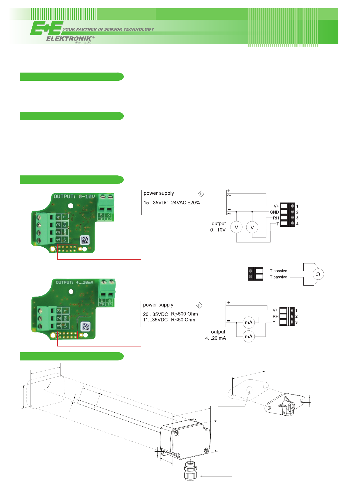
CONNECTION DIAGRAM
EE150-M1A3xx
(class III)
setup and adjustment interface (with EE-PCA)
EE150-M1A6xx
setup and adjustment interface (with EE-PCA)
DIMENSIONS / MOUNTING
63 (2.48)
ø 7
(ø 0.28)
ø 6
(ø 0.24)
28.55
(1.12)
(7.87)
T-passive connection for
EE150-M1A3xx / EE150-M1A6xx
5
6
(class III)
56 (2.2)
200
80.8 (3.18)
drilled hole for
mounting: ø>9 (ø>0.35)
ø 5 (ø 0.2)
Dimensions: mm (inch)
55.3 (2.18)
ø 4 (ø 0.16)
39.5 (1.56)
CABLE GLAND M16x1.5
Page 2

TECHNICAL DATA
(Modification rights reserved)
Measured values
Relative Humidity
Working range 10...90% RH
Accuracy at 20°C ±3% RH (30...70%RH), otherwise ±5% RH
Temperature dependency typ. ±0.05% RH/°C
Temperature
Working range -5...55°C
(23...131°F)
T-Accuracy at 20°C ±0.3°C
Outputs
Analog output 0-10 V R
(0...100% RH; T: see ordering guide) 4-20 mA (2-wire) R
Passive T-sensor
2-wire see ordering guide
Wires resistance (terminal - sensor) typ. 0.5 Ohm
≥ 10k Ohm
L
≤ 500 Ohm
L
General
Power supply (Class III)
for 0 - 10 V 15 - 35V DC or 24V AC ±20%
for 4 - 20 mA 10V + R
Current consumption with DC power supply typ. 5mA
with AC power supply typ. 13mA
Connection Screw terminals, max. 1.5 mm
Housing material Polycarbonate, UL94V-0 approved
Protection class IP65/NEMA 4
Cable gland M16 x 1.5
Sensor protection PTFE filter, non-removable
Electromagnetic compatibility EN61326-1 EN61326-2-3 Industrial environment
FCC Part 15 Class B ICES-003 Issue 5 Class B
Working conditions -5...55°C
Storage conditions -25...60°C
x 20 mA < UV < 35V DC
L
eff
2
(23...131°F) 0...95% RH (non-condensing)
(-13...140°F) 20...80% RH
SETUP AND ADJUSTMENT
The EE150 is ready to use and does not require any conguration by the user. The factory setup of EE150 corresponds to the type number ordered. For ordering guide please see data sheet at www.epluse.com/EE150.
If needed, the user can change the factory setup by using the optional E+E Product Configuration Adapter (EE-PCA) and the E+E
Product Configuration Software (EE-PCS). With these one can set the output scaling, and perform one or two point adjustment for
humidity and temperature.
For product data sheet EE-PCA please see www.epluse.com.
The E+E Product Configuration Software (EE-PCS) is free and can be downloaded from www.epluse.com/configurator.
USA
FCC notice:
This equipment has been tested and found to comply with the limits for a Class B digital device, pursuant to part 15 of the FCC Rules. These limits are
designed to provide reasonable protection against harmful interference in a residential installation. This equipment generates, uses and can radiate radio frequency energy and, if not installed and used in accordance with the installation manual, may cause harmful interference to radio communications.
However, there is no guarantee that interference will not occur in a particular installation. If this equipment does cause harmful interference to radio or
television reception, which can be determined by turning the equipment off and on, the user is encouraged to try to correct the interference by one or
more of the following measures:
- Reorient or relocate the receiving antenna.
- Increase the separation between the equipment and receiver.
- Connect the equipment into an outlet on a circuit different from that to which thereceiver is connected.
- Consult the dealer or an experienced radio/TV technician for help.
CANADIAN
ICES-003 Issue 5:
CAN ICES-3 B / NMB-3 B
INFORMATION
Langwiesen 7 • A-4209 Engerwitzdorf
Tel: +43 7235 605-0 • Fax: +43 7235 605-8
info@epluse.com • www.epluse.com
LG Linz Fn 165761 t • UID-Nr. ATU44043101
Place of Jurisdiction: A-4020 Linz • DVR0962759
+43 7235 605 0 / info@epluse.com
BA_EE150_e // v1.1 // Technische Änderungen vorbehalten
 Loading...