

Page 1
Langwiesen 7
A-4209 Engerwitzdorf
Austria
T: +43-7235-605-0 F: +43-7235-605-8
info@epluse.com www.epluse.com
BEDIENUNGSANLEITUNG SERIE EE10
MESSUMFORMER FÜR FEUCHTE / TEMPERATUR
ALLGEMEIN:
Messumformer der Serie EE10 sind für die exakte Erfassung von Feuchte und Temperatur bestimmt.
Das formschöne funktionelle Gehäuse ist für die direkte Wandmontage geeignet und ermöglicht eine
einfache Installation und im Servicefall einen raschen Wechsel der Sensoreinheit.
Anwendung findet die Serie EE10 im Bereich Klimaüberwachung (Wohn- und Bürobauten,
Schaltschränken, Museen und Hotels, etc.).
Extreme mechanische Beanspruchungen und unsachgemäße Handhabung sind unbedingt zu vermeiden!
Öffnen des Gehäuses:
Zapfen A eindrücken bis sich Deckel öffnen lässt.
Schließen des Gehäuses:
Deckel in Nut B einsetzen und in Richtung C schließen bis
Zapfen A einrastet.
Montage:
Gehäuse mittels Schrauben durch die dafür vorgesehen Löcher D
an eine Wand montieren.
Gehäusematerial: PC
Schutzart: IP30
Abmessungen
EU: 85 x 100 x 26 mm (BxHxT)
US: 85 x 136 x 26 mm (BxHxT)
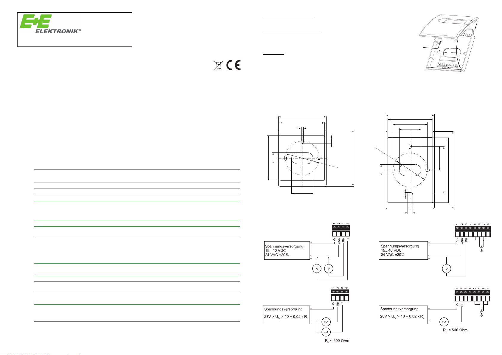
MONTAGEBOHRUNGEN:
MONTAGEBOHRUNGEN / MOUNTING HOLES
EU Version: US Version:
85 / 3.35“
79.7 / 3.14“
4 / 0.16“
85 / 3.35“
79.7 / 3.14“
60 / 2.36“
38.2 / 1.5“
B
A
Abmessungen: 85x100x26mm (BxHxT)
D
C
TECHNISCHE DATEN:
Messwerte
Relative Feuchte
Sensor HC103
Analogausgang 0...100% rF 0-10 V -1 mA < IL< 1mA
Arbeitsbereich
1)
Genauigkeit bei 20°C und UV=24VDC ±2% rF (40...60% rF) ±3% rF (10...90% rF)
Temperatureinfluss bei 60% rF typisch 0,06% rF / °C
Temperatur aktiv
Analogausgang 0...50°C
2)
Genauigkeit bei 20°C und UV=24VDC ±0,25°C (FT3) ±0,4°C (FT6)
Temperatur passiv
Typ T-Sensor siehe Bestellcode
Allgemein
Versorgungsspannung (UV)
für 0 - 10 V 15 - 40 VDC oder 24 VAC ±20%
für 4 - 20 mA 28V DC > UV> 10 + 0,02 x RL(RL< 500 Ohm)
Stromaufnahme bei DC Versorgung typ. 4 mA
Anschluss Schraubklemmen max. 1,5 mm
Anzeige bei Version EE10-FTx Feuchte / Temperatur alternierend
bei Version EE10-Fx bzw. EE10-FPx Feuchte
Elektromagnetische Verträglichkeit EN61326-1
Temperaturbereiche Betriebstemperatur: -5...+55°C
1) Bitte Arbeitsbereich des HC103 beachten!
2) andere Abbildungsbereiche auf Anfrage
bei AC Versorgung typ. 15 mA
4-20 mA (zwei Draht) RL< (UV-10)/0,02 < 500 Ohm
0...95% rF
0-10 V -1 mA < IL< 1mA
4-20 mA (zwei Draht) RL< (UV-10)/0,02 < 500 Ohm
eff
EN61326-2-3
Betriebstemperatur mit Display: -5...+55°C
Lagertemperatur: -25...+60°C
20
0.79“
80 / 3.15“
38.2 / 1.5“
Ø 60
2.36“
8 / 0.31“
100 / 3.94“
Ø 60
2.36“
20
0.79“
4 / 0.16“
41.65 / 1.64“
136 / 5.35“
114.2 / 4.5“
83.3 / 3.28“
ANSCHLUSSBILDER:
8 / 0.31“
EE10-F3
EE10-FT3
2
EE10-FT6
EE10-FP3
EE10-F6
EE10-FP6
BA_EE10_03 // Technische Änderungen vorbehalten
BA_EE10_02 // Technische Änderungen vorbehalten
Page 2
Langwiesen 7
Opening the housing:
Press pin A until cover can be opened.
Closing the housing:
Set cover into flute B and move it to direction C until pin A snaps in.
Installation:
Mount housing on wall with srews through therefore designated
holes D.
Material of housing: PC
Protection class: IP30
A
B
C
D
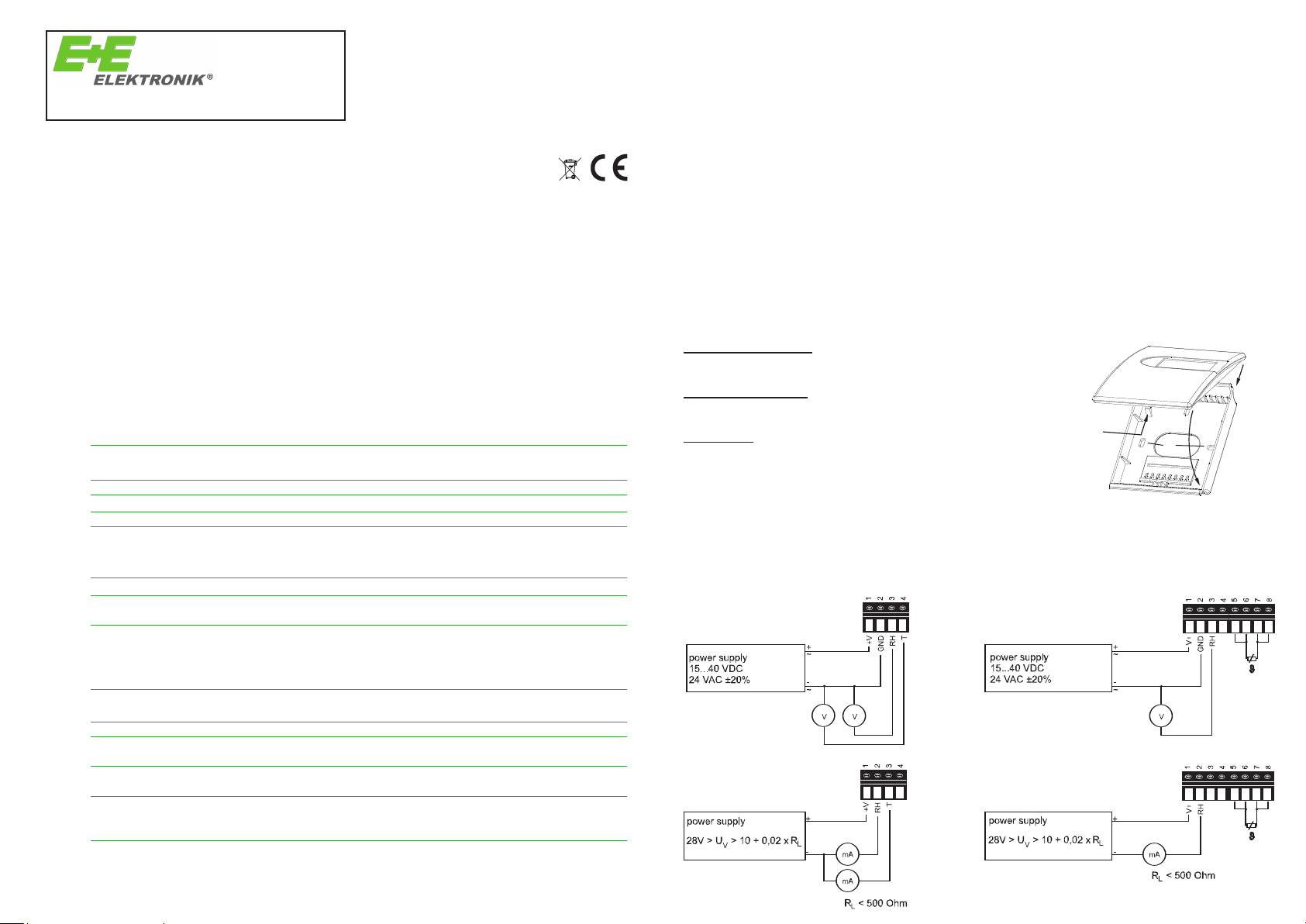
CONNECTION DIAGRAMS:
MOUNTING HOLES:
dimensions: 85x100x26mm (WxHxD)
EE10-FT3
EE10-FT6
EE10-F3
EE10-FP3
EE10-F6
EE10-FP6
Opening the housing:
Press pin A until cover can be opened.
Closing the housing:
Set cover into flute B and move it to direction C until pin A snaps in.
Installation:
Mount housing on wall with srews through therefore designated
holes D.
Material of housing: PC
Protection class: IP30
A
B
C
D
MOUNTING HOLES:
dimensions: 85x100x26mm (WxHxD)
T: +43-7235-605-0 F: +43-7235-605-8
info@epluse.com www.epluse.com
A-4209 Engerwitzdorf
Austria
MANUAL EE10 SERIES
TRANSMITTER FOR HUMIDITY / TEMPERATURE
GENERAL:
EE10 transmitter series are designed for accurate measurement of humidity and temperature.
The stylish, functional housing for wall mounting makes easy installation and fast exchange of the sensing
unit for service purposes possible.
Main application for the EE10 is climate control in residential and office areas, switching cabines, hotels
and museums, etc.
Absolutely avoid extreme mechanical and unspecified strain!
TECHNICAL DATA:
Measuring Quantities
Relative Humidity
Humidity sensor HC103
Analogue output 0...100 % RH 0-10 V -1 mA < IL< 1mA
Working range
1)
Accuracy at 20°C (68°F) and UV=24VDC ±2% RH (40...60% RH) ±3% RH (10...90% RH)
Temperature influence at 60% RH typical 0.06% RH /°C (0.03% RH / °F)
Temperature (active output)
Analogue output 0...50°C (32...122°F)
Accuracy at 20°C (68°F) and UV=24VDC FT3: ±0.25°C (±0.45°F) FT6: ±0.4°C (±0.72°F)
Temperature (passive output)
Type of T-Sensor please see ordering guide
General Data
Voltage supply (U
)
V
for 0 - 10 V 15 - 40 VDC or 24 VAC ±20%
for 4 - 20 mA 28V DC > UV> 10 + 0.02 x RL(RL< 500 Ohm)
Current consumption for DC supply: typical 4 mA
Electrical connection screw terminals max. 1.5 mm
Display for EE10-FTx version humidity / temperature alternating
for EE10-Fx and EE10-FPx version humidity
CE compatibility according EN61326-1
Temperature ranges working temperature range: -5...55°C (23...131°F)
1) Please refer to the working range of the HC103
2) Other T-scaling on request
4-20 mA (two wires) RL< (UV-10)/0.02 < 500 Ohm
0...95 % RH
2)
0-10 V -1 mA < IL< 1mA
4-20 mA (two wires) RL< (UV-10)/0.02 < 500 Ohm
for AC supply: typical 15 mA
2
(AWG 16)
eff
EN61326-2-3
working temperature with display: -5...55°C
storage temperature range: -25...60°C (-13...140°F)
(23...131°F)
USA
FCC notice:
This equipment has been tested and found to comply with the limits for a Class B digital device, pursuant to part 15 of the FCC Rules. These limits are designed to provide reasonable protection against
harmful interference in a residential installation. This equipment generates, uses and can radiate radio
frequency energy and, if not installed and used in accordance with the installation manual, may cause
harmful interference to radio communications. However, there is no guarantee that interference will not
occur in a particular installation. If this equipment does cause harmful interference to radio or television
reception, which can be determined by turning the equipment off and on, the user is encouraged to try
to correct the interference by one or more of the following measures:
• Reorient or relocate the receiving antenna.
• Increase the separation between the equipment and receiver.
• Connect the equipment into an outlet on a circuit different from that to which thereceiver is connec-
ted.
• Consult the dealer or an experienced radio/TV technician for help.
CANADIAN
ICES-003 Issue 5:
CAN ICES-3 B / NMB-3 B
Opening the housing:
Press pin A until cover can be opened.
Closing the housing:
B
Set cover into flute B and move it to direction C until pin A snaps in.
allation:
Inst
Mount housing on wall with srews through therefore designated
A
D
holes D.
Material of housing: PC
Protection class: IP30
CONNECTION DIAGRAMS:
EE10-FT3
Dimensions:
EU: 85 x 100 x 26 mm (WxHxD) (3.35 x 3.94 x 1.02“)
dimensions: 85x100x26mm (WxHxD)
US: 85 x 136 x 26 mm (WxHxD) (3.35 x 5.35 x 1.02“)
EE10-F3
EE10-FP3
C
EE10-FT6
EE10-F6
EE10-FP6
technical data are subject to change
 Loading...