

Page 1

Serie EE08
FEUCHTE / TEMPERATUR
MESSUMFORMER
HUMIDITY / TEMPERATURE
TRANSMITTER
TRANSMETTEUR DE MESURE
D'HUMIDITE / DE TEMPERATURE
BA_EE08_d_e_f_01 // technical data are subject to change // 302455
BEDIENUNGSANLEITUNG
MANUAL
MANUEL D'INSTRUCTION
Page 2

HARDWARE:
INHALTSVERZEICHNIS
1. ALLGEMEIN 4
1.1 Symbolerklärung 4
1.2 Sicherheitshinweise 4
2. BAUFORMEN 4
3. ANSCHLUSSBILD 5
4. MONTAGEHINWEISE 5
5. INSTANDHALTUNG 5
6. ZUBEHÖR / ERSATZTEILE 6
7. KALIBRATION / JUSTAGE 6
8. TECHNISCHE DATEN 6
E2 / RS232 KONVERTERKIT ZUR KALIBRATION / JUSTAGE:
1. LIEFERUMFANG 7
2. ANSCHLUSSBILD 7
3. KALIBRATIONSSOFTWARE 8
3.1 Installation 8
3.2 Menüpunkte 8
3.2.1 Datei 8
3.2.2 Hilfe 8
3.3 Kartei-Reiterkarten 8
3.3.1 Start 8
3.3.2 Kalibration 9
3.3.3 Messwerte 10
3.3.4 Information 11
HARDWARE:
1. GENERAL 12
1.1 Symbol assertion 12
1.2 Safety instructions 12
2. MODELS 12
3. CONNECTION DIAGRAM 13
4. INSTALLATION INSTRUCTIONS 13
5. MAINTENANCE 13
6. ACCESSORIES / REPLACEMENT PARTS 14
7. CALIBRATION / ADJUSTMENT 14
8. TECHNICAL DATA 14
E2 / RS232 CONVERTER KIT FOR CALIBRATION / ADJUSTMENT:
1. SCOPE OF SUPPLY 15
2. CONNECTION DIAGRAM 15
3. CALIBRATION SOFTWARE 16
3.1 Installation 16
3.2 Icons on the toolbar 16
3.2.1 File 16
3.2.2 Help 16
3.3 Index - Index Cards 16
3.3.1 Start 16
3.3.2 Calibration 17
3.3.3 Measuring values 18
3.3.4 Information 18
SOMMAIRE
MATERIEL:
TABLE OF CONTENTS
1. GENERALITES 20
1.1 Explication des symboles 20
1.2 Consignes de sécurité 20
2. MODELES 20
3. RACCORDEMENTS ELECTRIQUES 21
4. INSTALLATION 21
5. DEPANNAGE / MAINTENANCE 21
6. ACCESSOIRES / PIECES DE RECHANGE 22
7. CALIBRATION / AJUSTAGE 22
8. CARACTERISTIQUES TECHNIQUES 22
KIT DE CONVERSION E2 / RS232 POUR CALIBRATION / AJUSTAGE:
1. LIVRAISON STANDARD 23
2. RACCORDEMENT ELECTRIQUES 23
3. LOGICIEL DE CALIBRATION 24
3.1 Installation 24
3.2 Menu 24
3.2.1 Fichier 24
3.2.2 Aide 24
3.3 Cartes convertisseur 24
3.3.1 Démarrage 24
3.3.2 Calibration 25
3.3.3 Valeurs mesurées 26
3.3.4 Information 26
Page 3

USA
FCC Hinweis:
Dieses Gerät ist geprüft worden und stimmt mit den Bedingungen für ein Gerät der Kategorie B gemäß
Teil 15 der FCC Richtlinien überein. Diese Bedingungen sind erstellt worden um einen angemessenen
Schutz gegen EMV Störungen in einem Wohnbereich sicherzustellen. Dieses Gerät erzeugt, verbraucht
und kann Hochfrequenzenergie ausstrahlen. Wenn es nicht in Übereinstimmung mit der
Bedienungsanleitung installiert und verwendet wird, können EMV Störungen zu den Funkverbindungen
verursacht werden. Jedoch gibt es keine Garantie, dass EM Störungen nicht in einer bestimmten
Installation auftreten können. Wenn das Gerät EMV Störungen zum Radio oder Fernsehempfang verursacht (das kann festgestellt werden indem man das Gerät ein- und ausschaltet), wird dem Benutzer
empfohlen die EMV Störungen durch folgende Maßnahmen zu beheben:
- Stellen Sie die Antenne neu ein oder verlagern Sie die empfangende Antenne.
- Erhöhen Sie den Abstand zwischen dem Gerät und dem Empfänger.
- Schließen Sie das Gerät an einem anderen Stromkreis als den Empfänger an.
- Fragen Sie den Händler oder einen erfahrenen Radio/TV Techniker.
Vorsicht:
Änderungen am Gerät die nicht ausdrücklich durch einen EMV Beauftragten genehmigt sind können
dazu führen, dass der Betreiber das Gerät nicht mehr gebrauchen darf.
KANADA
ICES-003 Bescheid:
Dieses Gerät der Kategorie B entspricht der kanadischen Norm ICES-003.
USA
FCC notice:
This equipment has been tested and found to comply with the limits for a Class B digital device, pursuant
to part 15 of the FCC Rules. These limits are designed to provide reasonable protection against harmful
interference in a residential installation. This equipment generates, uses and can radiate radio frequency
energy and, if not installed and used in accordance with the installation manual, may cause harmful
interference to radio communications. However, there is no guarantee that interference will not occur in
a particular installation. If this equipment does cause harmful interference to radio or television reception,
which can be determined by turning the equipment off and on, the user is encouraged to try to correct
theinterference by one or more of the following measures:
- Reorient or relocate the receiving antenna.
- Increase the separation between the equipment and receiver.
- Connect the equipment into an outlet on a circuit different from that to which the receiver is connected.
- Consult the dealer or an experienced radio/TV technician for help.
Caution: Any changes or modifications not expressly approved by the party responsible for compliance
could void the user's authority to operate this device.
CANADIAN
ICES-003 notification:
This Device B digital apparatus complies with Canadian ICES-003.
Cet appareil numérique de la classe B est conforme à la norme NMB-003 du Canada.
USA
Consigne FCC:
Cet appareil a été contrôlé et répond aux exigences relatives aux appareils de catégorie B conformément
à la partie 15 des directives FCC. Ces exigences ont été établies afin d’assurer une protection raisonnable (CEM) contre les perturbations électromagnétiques dans les habitations. Cet appareil génère,
consomme et peut diffuser de l’énergie haute fréquence. Les liaisons radio peuvent subir des perturbations électromagnétiques dès lors qu’il n’est pas installé et exploité conformément au manuel d’utilisation.
Néanmoins, des perturbations électromagnétiques peuvent apparaître dans une installation donnée. Si
l’appareil cause des perturbations électromagnétiques à la réception radio ou TV (ceci peut être vérifié
en mettant l’appareil en marche, puis à l’arrêt), il est conseillé à l’utilisateur d’éliminer les perturbations
électromagnétiques en prenant les mesures suivantes :
- Revoir le réglage de l’antenne de réception, ou déplacer l’antenne.
- Augmenter la distance séparant l’appareil du récepteur.
- Brancher l’appareil à un circuit électrique distinct de celui du récepteur.
- Contacter le revendeur ou faire appel à un technicien spécialisé radio/TV.
Attention :
Toute modification apportée à l’appareil sans l’aval préalable d’un délégué CEM
peut entraîner l’interdiction d’exploiter l’appareil.
CANADA
Conformité ICES-003:
Cet appareil de catégorie B correspond à la norme canadienne ICES-003.
3
Page 4
HARDWARE
1. ALLGEMEIN
Die Bedienungsanleitung ist Bestandteil des Lieferumfanges und dient der Sicherstellung
einer sachgemäßen Handhabung und optimalen Funktion des Gerätes.
E+E Elektronik® Ges.m.b.H. übernimmt für diese Publikation keinerlei Garantie und bei
unsachgemäßer Handhabung der beschriebenen Produkte keinerlei Haftung.
Aus diesem Grund muss die Bedienungsanleitung unbedingt vor Inbetriebnahme gelesen werden.
Darüber hinaus ist die Bedienungsanleitung jeglichen Personen, welche mit dem Transport,
der Aufstellung, dem Betrieb, der Wartung und Reparatur befasst sind, in Kenntnis zu bringen.
Diese Bedienungsanleitung darf nicht ohne das schriftliche Einverständnis von
E+E Elektronik® zu Zwecken des Wettbewerbes verwendet und auch nicht an Dritte weitergegeben werden.
Kopien für den Eigenbedarf sind erlaubt.
Diese Publikation kann technische Ungenauigkeiten oder typographische Fehler enthalten.
Die enthaltenen Informationen werden regelmäßig überarbeitet und unterliegen nicht dem
Änderungsdienst. Der Hersteller behält sich das Recht vor, die beschriebenen Produkte
jederzeit zu modifizieren bzw. abzuändern.
© Copyright E+E Elektronik® Ges.m.b.H. Alle Rechte vorbehalten.
1.1 Symbolerklärung
Dieses Zeichen zeigt Sicherheitshinweise an.
Sicherheitshinweise sind unbedingt zu befolgen. Bei Nichtbeachtung können Verletzungen
von Personen oder Sachschäden entstehen. E+E Elektronik® übernimmt dafür keine Haftung.
Dieses Zeichen zeigt einen Hinweis an.
Um eine optimale Funktion des Gerätes zu erreichen, sind diese Hinweise einzuhalten.
1.2 Sicherheitshinweise
• Übermäßige mechanische und unsachgemäße Beanspruchungen sind unbedingt
zu vermeiden.
• Vorsicht beim Abschrauben der Filterkappe, da das Sensorelement beschädigt
werden kann.
• Beim Sensorelement handelt es sich um ein ESD gefährdetes Bauteil, d.h. beim
Berühren des Sensorelementes sind ESD-Schutzmaßnahmen einzuhalten.
• Sensoren nur an den Anschlussdrähten anfassen.
• Montage, elektrischer Anschluss, Wartung und Inbetriebnahme dürfen nur von
dazu ausgebildetem Fachpersonal durchgeführt werden.
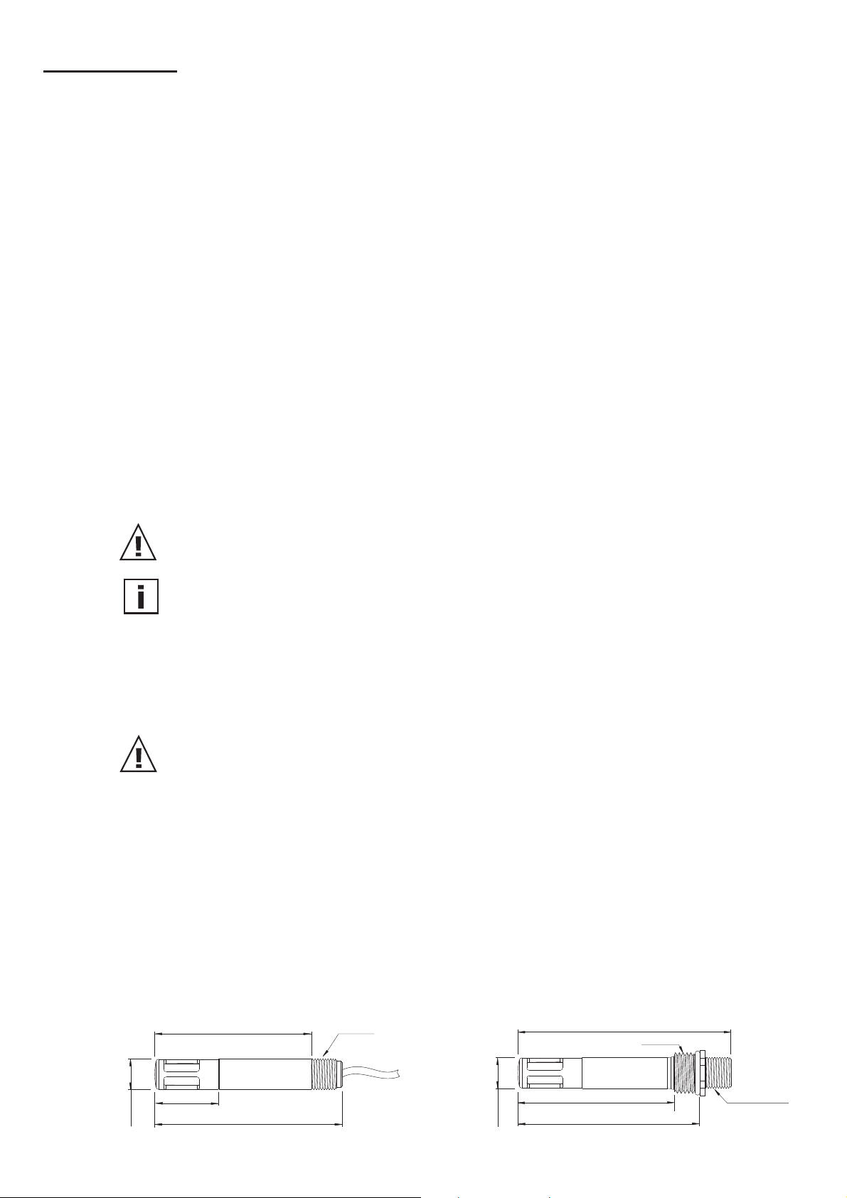
2. BAUFORMEN
Anschluss mit Kabel
EE08-PFTxExxx
61
25
∅12
73
M12x1
Anschluss mit Steckverbindung
EE08-PFTxDxxx
83
M16x1,5
61
∅12
4
4
71
Stecker M12
(8-polig)
Page 5
3. ANSCHLUSSBILD
TYP E:
TYP D:
Temperatur aktiv Temp. passiv, 4 Draht
Kabelbelegung Kabelbelegung
T-passiv weiß (nicht belegt) weiß, schwarz
T-passiv blau (nicht belegt) blau, violett
GND rosa rosa
T-out grau grau (nicht belegt)
RH-out gelb gelb
SCL grün grün
SDA braun braun
+UB rot rot
E2-
}
Schnittstelle
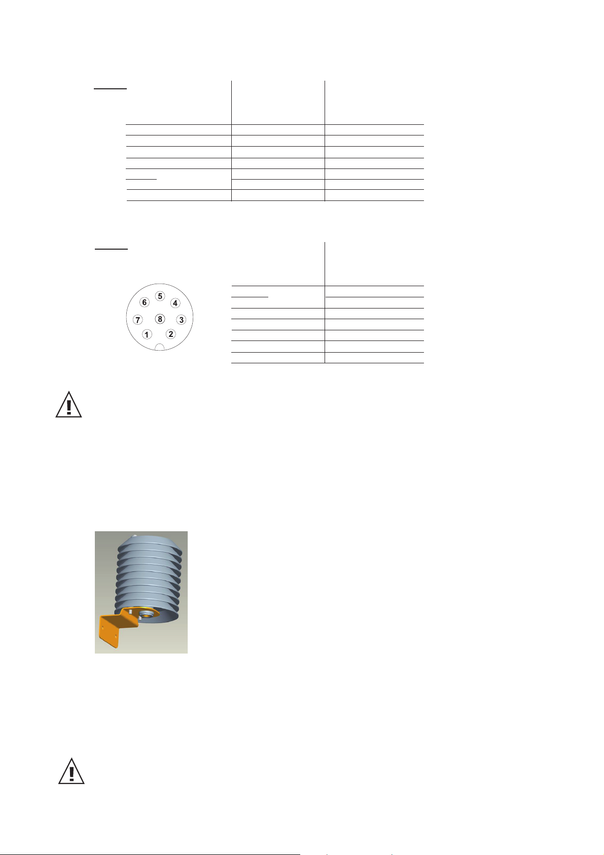
Pin Belegung Belegung von M12 Anschlusskabel
(HA010322, HA010323, HA010324, HA010325)
1 T-passiv weiß
2 SDA braun
3 SCL grün
4 RH-out gelb
5 T-out grau
6 GND rosa
7 T-passiv blau
8 +UB rot
E2-
}
Schnittstelle
Schirmanbindung:
Nach Möglichkeit ist die Schirmung des Anschlusskabels niederohmig und breitbandig (großflächig) an
das Erdpotential anzubinden.
4. MONTAGEHINWEISE
Bei einer Außenmontage ist gegen Überhitzung durch Sonneneinstrahlung und zum Schutz
vor Regen und anderen Umwelteinflüssen ein Strahlungsschutz zu verwenden.
Der Strahlungsschutz inkl. Montagewinkel, passend für Bauform D und E, ist als Zubehör
erhältlich (Bestellcode: HA010506).
5. INSTANDHALTUNG
Filter auf Verschmutzung prüfen und gegebenenfalls austauschen.
Feuchtesensor auf Verunreinigungen oder Schmutzablagerungen prüfen und falls
erforderlich reinigen:
Sensorelement in Isoprophyl - Alkohol und anschließend in DI-Wasser schwenken, danach
ablüften lassen.
Achtung: Feuchtesensor nicht berühren!
Bei zweifelhaften / abweichenden Feuchte- oder Temperaturmesswerten sollte eine Kalibration
und gegebenenfalls eine Justage des Messumformers erfolgen.
5
5
Page 6
6. ZUBEHÖR / ERSATZTEILE
Bezeichnung Bestellcode
Strahlungsschutz HA010506
E2 / RS232 Konverter + Kalibrationssoftware HA011005
M12 Anschlusskabel für Typ D, 1,5m HA010322
M12 Anschlusskabel für Typ D, 3m HA010323
M12 Flanschdose mit Litzen HA010703
M12 Kabeldose konfektionierbar HA010704
Metallgitterfilter HA010113
Membranfilter HA010101
Edelstahlsinterfilter HA010103
PTFE-Filter HA010105
7. KALIBRATION / JUSTAGE
Um eine 1 Punkt bzw. 2 Punkt Feuchte- oder Temperaturkalibration / -justage durchzuführen, ist der als Zubehör erhältliche E2 / RS232-Konverterkit mit Software erforderlich
(Bestellcode HA011005).
Messwerte
Relative Feuchte
Sensor HC101
Arbeitsbereich
Digitalausgang (2 Draht)
Analogausgang 0...100% rF 0-1/2,5/5/10V -0,2mA < I
Genauigkeit bei 20°C und 12V DC ±2% rF (0...90% rF) ±3% rF (90...100% rF)
Temperaturabhängigkeit typ. 0,03% rF/°C
Temperatur
Sensor Pt 1000 (DIN A)
Digitalausgang (2 Draht)
Analogausgang 0-1/2,5/5/10V -0,2mA < I
Genauigkeit bei 12V DC
Allgemeines
Versorgungsspannung Ausgang 0-1V / 0-2,5V 4,5-15V DC oder 7-30V DC
Ausgang 0-5V 7-30V DC
Ausgang 0-10V 12-30V DC
Temperaturabhängigkeit der Analogausgänge ±0,08 mV/°C
Stromaufnahme typ. < 1,3mA
Digitale Schnittstelle E2-Schnittstelle Pegel = 3,3V / ±0,1V
Gehäuse Polycarbonat / IP65
Sensorschutz Metallgitterfilter
Elektromagnetische Verträglichkeit EN61326-1 EN61326-2-3
Industrieumgebung
Temperaturbereiche Betriebstemperatur: -40...+80°C
Lagertemperatur: -40...+80°C
1) Bitte Arbeitsbereich des HC101 beachten 2) Serielles Protokoll: siehe www.epluse.com
8. TECHNISCHE DATEN
1)
0...100% rF
2)
Ausgabewert: 0,00...100,00% rF
2)
Ausgabewert: -40,00...+80,00°C
Δ°C
< 0,2mA
L
< 0,2mA
L
°C
6
6
Page 7
E2 / RS232 KONVERTERKIT ZUR KALIBRATION / JUSTAGE
(Bestellcode HA011005)
1. LIEFERUMFANG
- E2 / RS232 - Konverter
- Versorgungs- und Kontaktierungseinheit
- Anschlusskabel EE08-PFTxDxxx (inkl. Anschlussstecker + Klemmleiste)
- Klemmleiste für EE08-PFTxExxx
- CD mit Kalibrations- / Justagesoftware
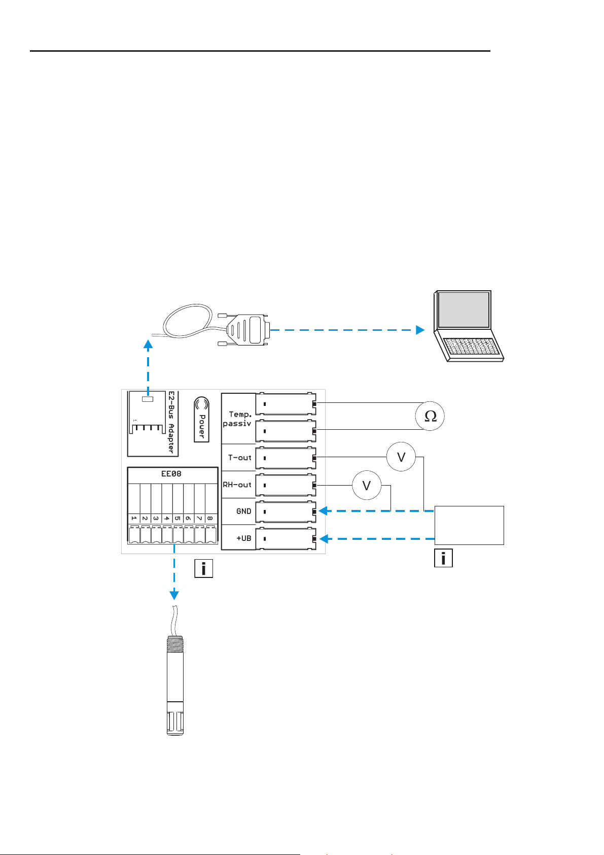
2. ANSCHLUSSBILD
rosa
blau
weiß
EE08-PFTxDxxx
EE08-PFTxExxx
max. Kabellänge: 10m
E2-Schnittstelle - RS232 Konverter
rot
braun
grün
gelb
grau
Hinweis:
Um Kurzschlüsse zu vermeiden, sind alle 8 Litzen
des Anschlusskabels
(EE08-PFTxExxx) an der
8-poligen Klemmleiste
aufzulegen.
Spannungsversorgung
12V DC ±10%
Hinweis:
Externe Versorgung notwendig!
7
7
Page 8
3. KALIBRATIONSSOFTWARE
HAFTUNGSEINSCHRÄNKUNG
E+E Elektronik® haftet nicht für irgendwelche Schäden bzw. Folgeschäden (beispielsweise, aber nicht beschränkt
auf Gewinn-Entgang, Geschäftsunterbrechung, Informations- und Datenverlust oder irgendwelchen anderen
Vermögensschäden), die durch Installation, Verwendung und auch Unmöglichkeit der Verwendung eines
Softwareprodukts von E+E Elektronik
Nichtleistung von Support entstehen.
3.1 Installation
Hinweis: Um eine reibungslose Installation der EE08 Kalibrationssoftware zu ermöglichen,
können eventuell Administratorberechtigungen erforderlich sein!
1. Beiliegende CD-ROM in das entsprechende Laufwerk des PCs einlegen.
2. Zur Installation der EE08 Kalibrationssoftware das File "Setup.exe" ausführen.
3. Der Installshield-Wizard für den EE08 Kalibrator wird gestartet.
4. Den Anweisungen folgen um die Installation auszuführen.
5. Mit dem Betätigen der Taste "Fertigstellen" wird die Installation der Kalibrationssoftware erfolgreich
abgeschlossen.
Beim ersten Start der EE08 Kalibrationssoftware wird die gewünschte Programmsprache und die serielle
Schnittstelle (z.B. COM1) eingestellt.
Systemvoraussetzungen: ab MS WINDOWS 98®; serielle Schnittstelle
®
und eventuell damit zusammenhängenden Supportleistungen bzw.
3.2 Menüpunkte
3.2.1 Datei
- COM Port wählen: Auswahl der zur Kommunikation verwendeten Schnittstelle
- Beenden: Programm beenden
3.2.2 Hilfe
- Handbuch öffnen: öffnet EE08 Bedienungsanleitung
- Info über... Allgemeine Informationen zur Kalibrationssoftware
3.3 Kartei-Reiterkarten
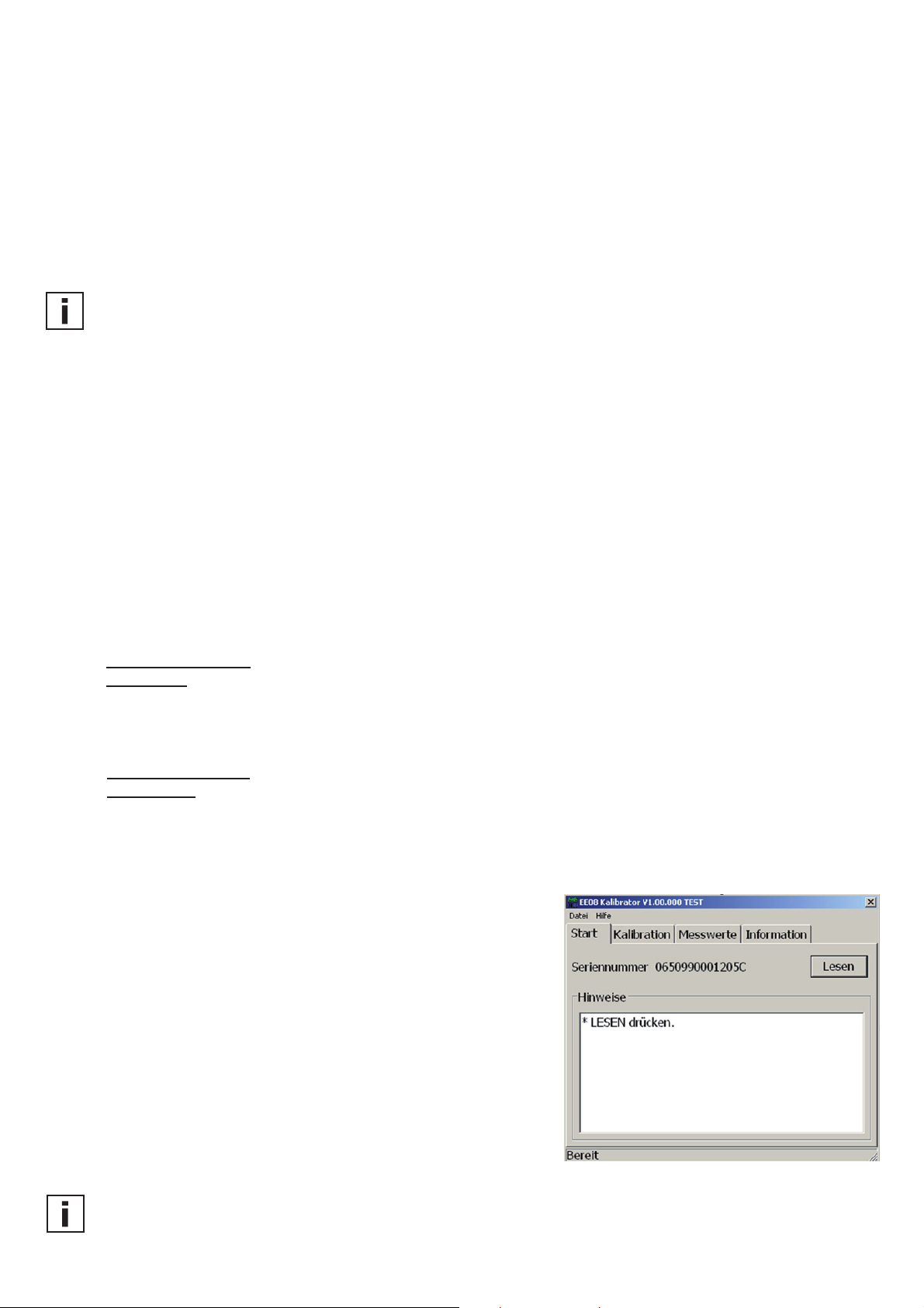
3.3.1 Start
Kalibrationsablauf:
1. EE08 gemäß Anschlussbild mit dem Konverterkit (HA011005)
und PC verbinden.
2. Kalibrationssoftware öffnen.
3. Push-Button “LESEN” drücken.
4. Transmitterdaten (z.B. Seriennummer, Ausgangssignal...)
werden gelesen und angezeigt.
5. Gewünschte Kalibration vornehmen (in der Reiterkarte
"Kalibration").
Hinweis:
Änderungen immer erst nach dem LESEN (Aktualisieren) der Transmitterdaten vornehmen!
8
8
Page 9
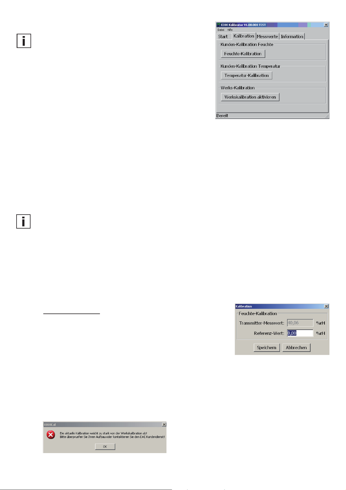
3.3.2 Kalibration
Allgemeine Hinweise:
Der EE08 Konfigurator unterscheidet folgende Kalibrationspunkte:
Unterer Kalibrationspunkt:
Ist der gewählte Kalibrationspunkt kleiner als die Messbereichsmitte,
wird er automatisch als "unterer Kalibrationspunkt" erkannt.
Oberer Kalibrationspunkt:
Ist der gewählte Kalibrationspunkt größer als die Messbereichsmitte,
wird er automatisch als "oberer Kalibrationspunkt" erkannt.
Bsp: rF-Messbereich = 0-100% rF -> Messbereichsmitte = 50% rF
- gewählter Kalibrationspunkt = 10% rF = < 50% rF = unterer Kalibrationspunkt
- gewählter Kalibrationspunkt = 80% rF = > 50% rF = oberer Kalibrationspunkt
1-Punkt Kalibration:
Wird der EE08 nur in einem Punkt (unterer ODER oberer Kalibrationspunkt) kalibriert / justiert, spricht man von
einer 1-Punkt Kalibration. Diese ist einfach und rasch durchzuführen, garantiert aber nur genaue Messergebnisse
in einem sehr eingeschränkten Arbeitsbereich (z.B.: Arbeitsbereich von 10...30% rF => 1-Pkt. Kalibration bei 20% rF).
2-Punkt Kalibration:
Wird der EE08 in 2 Punkten kalibriert (unterer UND oberer Kalibrationspunkt) spricht man von einer 2 Punkt
Kalibration. Diese ist aufwendiger in der Durchführung, garantiert aber genaue Messergebnisse über den
gesamten Arbeitsbereich.
Hinweis:
- Der untere Kalibrationspunkt soll im unteren Drittel des Messbereiches liegen.
- Der obere Kalibrationspunkt soll im oberen Drittel des Messbereiches liegen.
Bsp.: rF-Messbereich = 0...100% rF
- Untere Kalibrationspunkt: 0...30% rF
- Obere Kalibrationspunkt: 70...100% rF
Feuchte-Kalibration:
1. Positionierung des Fühlers in der Feuchte-Referenz.
2. Kalibrationspunkt am Referenzsystem wählen (z.B. unterer Punkt: 20%rF).
3. Stabilisierungszeit (ca. 30 Minuten) abwarten.
4. Schaltfläche "Feuchte-Kalibration" drücken.
5. Ersetzen Sie den angezeigten Referenz-Wert durch den tatsächlich
im Referenz-System vorherrschenden Wert.
6. Durch "Speichern" wird der Transmitter Messwert des EE08 auf den vorherrschenden Referenz-Wert angeglichen.
7. Eine 1 Punkt Kalibration / Justage wurde somit durchgeführt.
8. Um eine 2 Punkt Kalibration durchzuführen, oberen Kalibrationspunkt am Referenzsystem wählen.
9. Punkt 3 bis 6 wiederholen.
Anmerkung:
Weichen die EE08 Transmitter Messwerte ungewöhnlich weit vom Referenzwert ab, kann ein Abgleich / eine
Justage nicht erfolgen. Folgende Fehlermeldung erscheint:.
9
9
Page 10

Temperatur-Kalibration:
Durch Drücken der Schaltfläche "Temperatur-Kalibration" wird eine 1-Punkt oder 2-Punkt Temperaturkalibration
gestartet.
1. Positionieren des Fühlers in der Temperatur-Referenz.
2. Der weitere Ablauf entspricht der Feuchte-Kalibration Punkt 2-9.
Werkskalibration aktivieren:
Durch Drücken der Schaltfläche "Werkskalibration aktivieren", werden die Kundenkalibrationsdaten für Feuchte und
Temperatur gelöscht und auf die ursprünglichen Werkseinstellungen rückgesetzt.
3.3.3 Messwerte
Die Kalibrationssoftware bietet auch die Möglichkeit, die am
digitalen Ausgang des EE08 bereitgestellten Messwerte für Feuchte
und Temperatur anzuzeigen / zu prüfen.
Wird das Kontrollkästchen "automatische Abfrage" aktiviert,
werden die Messwerte, dem definierten Intervall entsprechend,
abgefragt und die Anzeige aktualisiert.
3.3.4 Information
In diesem Bereich der Kalibrationssoftware werden die Stammdaten
des Messumformers angezeigt:
Type: EE08
Ausgang: Ausgangssignal des ausgelesenen EE08
Temperatur: Abbildungsbereich Temperaturausgang
Feuchte: Abbildungsbereich Feuchteausgang
Seriennummer: Seriennummer des ausgelesenen EE08
Letzte Kunden_Kalibration:
Datum der letzten Kundenkalibration am
ausgelesenen EE08.
Anmerkung:
Wurde bisher noch keine Kundenkalibration durchgeführt, wird Werkskalibration angezeigt.
In der letzten Zeile wird die Versionsnummer des verwendeten E2/RS232-Adapters (Konverters) angezeigt.
10
10
Page 11

11
Page 12

HARDWARE
1. GENERAL
1.1 Symbol assertion
The manual is a part of the scope of supply and serves to ensure proper handling and
optimum functioning of the instrument.
E+E Elektronik® Ges.m.b.H. doesn't accept warranty and liability claims neither upon this
publication nor in case of improper treatment of the described products.
For this reason, the manual must be read before start-up.
In addition, the manual is for all personnel who require knowledge concerning transport,
setup, operation, maintenance and repair.
The manual must not be used for the purpose of competition without a written consent from
E+E Elektronik® and must also not be forwarded to third parties.
Copies for personal use are permitted.
The document may contain technical inaccuracies and typographical errors. The content will
be revised on a regular basis. These changes will be implemented in later versions.
The described products can be improved and changed at any time without prior notice.
© Copyright E+E Elektronik® Ges.m.b.H. All rights reserved.
This symbol indicates a safety instruction.
These safety instructions should always be followed carefully. By not following these instructions
injuries of persons or material damage could happen.Therefore E+E Elektronik
This symbol indicates a note.
These notes should be followed to achieve optimum functioning of the equipment.
1.2 Safety instructions
• Extreme mechanical stress and improper use must be avoided.
• Be careful when removing the filter cap to avoid damage of the sensor element.
• The sensor is an Electro Static Discharge sensitive component (ESD). When
touching the sensor element, ESD protective measures should be followed.
• Hold the sensor on its connection wires only.
• Installation, electrical connection, maintenance and start-up procedures should be executed
by qualified technical personel only.
®
does not accept liability.
2. MODELS
EE08 with cable
EE08-PFTxExxx
61
(2.4”)
25 (0.98”)
∅12 (0.47”)
73 (2.87”)
M12x1
EE08 with connector
EE08-PFTxDxxx
∅12 (0.47”)
12
83 (3.27”)
61 (2.4”)
71 (2.8”)
M16x1.5
connector M12
(8-pole)
Page 13

3. CONNECTION DIAGRAM
TYPE E:
TYPE D:
Temperature active Temp. passive, 4 wire
cable assignment cable assignment
T-passive white (not connected) white, black
T-passive blue (not connected) blue, violet
GND pink pink
T-out grey grey (not connected)
RH-out yellow yellow
SCL green green
SDA brown brown
+UB red red
E2-
}
interface
Pin assignment Assignment of M12 connection cable
(HA010322, HA010323, HA010324, HA010325)
1 T-passive white
2 SDA brown
3 SCL green
4 RH-out yellow
5 T-out grey
6 GND pink
7 T-passive blue
8 +UB red
E2-
}
interface
Shield connection:
If possible, connect the shield of the connection cable to the ground potential over a wide area,
with low-impedance.
4. INSTALLATION INSTRUCTIONS
For installation outdoors, use a radiation shield to provide protection against rain and other
ambient conditions and to prevent overheating caused by direct sunlight.
The radiation shield with mounting bracket, suitable for models D and E, is available as an
accessory (order code: HA010506).
5. MAINTENANCE
Check filter for soiling and, if necessary, replace.
Check humidity sensor for soiling or dirt build-up and, if necessary, clean:
Rinse the sensor element in isopropyl alcohol followed by deionised water before allowing it
to dry.
Note: do not touch the humidity sensor!
If the humidity or temperature measuring values are unclear / deviating, calibrate the
transmitter and, if necessary, adjust.
13
Page 14

6. ACCESSORIES / REPLACEMENT PARTS
Description Order Code
radiation shield HA010506
E2 / RS232 converter + calibration software HA011005
M12 connection cable for type D, length 1.5m
M12 connection cable for type D, length 3m (10ft) HA010323
M12 female socket with wires HA010703
M12 female cable connector assembly possible HA010704
metal grid filter HA010113
membrane filter HA010101
stainless steel sintered filter HA010103
PTFE filter HA010105
7. CALIBRATION / ADJUSTMENT
To carry out an one point or a two point calibration / adjustment, the E2 / RS232
converter + calibration software is necessary (available as an accessory, order code
HA011005).
8. TECHNICAL DATA
(5ft) HA010322
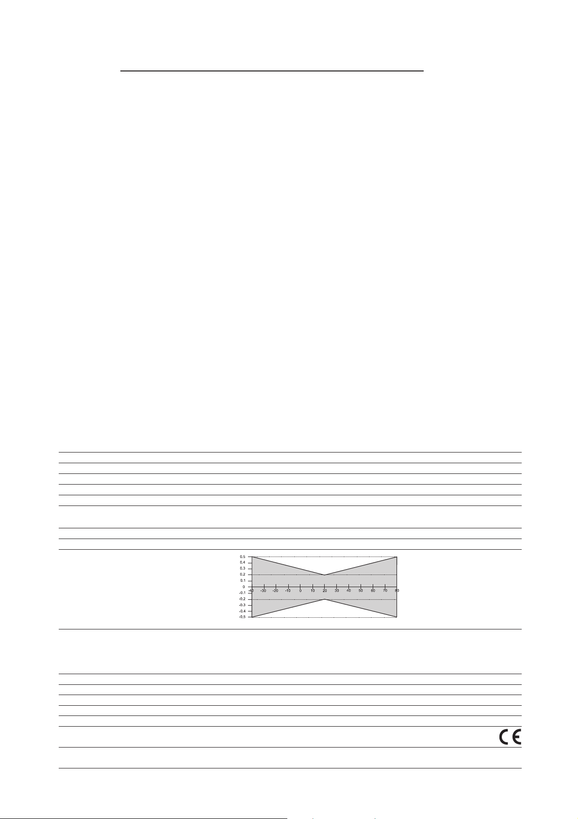
Measuring values
Relative Humidity
Sensor HC101
Working range
Digital output (2 wire)
Analogue output 0...100% RH 0-1/2.5/5/10V -0.2mA < I
Accuracy at 20°C
Traceable to intern. standards, administrated by NIST, PTB, BEV...
Temperature dependence typ. 0.03% RH/°C
Temperature
Sensor Pt 1000 (DIN A)
Digital output (2 wire)
Analogue output 0-1/2.5/5/10V -0.2mA < I
Accuracy at 12V DC
General
Supply voltage output 0-1V / 0-2.5V 4.5-15V DC or 7-30V DC
output 0-5V 7-30V DC
output 0-10V 12-30V DC
Temperature dependence of analogue outputs ±0.08 mV/°C
Current consumption typ. < 1.3mA
Digital interface E2-interface level = 3.3V / ±0.1V
Housing polycarbonate / IP65
Sensor protection metal grid filter
Electromagnetic compatibility EN 61000-6-3
EN 61000-6-2
Temperature ranges working temperature: -40...80°C
storage temperature: -40...80°C (-40...176°F)
1) refer to the working range of the humidtiy sensor HC101 2) serial protocol refer to www.epluse.com
1)
0...100% RH
2)
output value: 0.00...100.00% RH
< 0.2mA
(68°F) and 12V DC ±2% RH (0...90% RH) ±3% RH (90...100% RH)
(typ. 0.02% RH/°F)
2)
output value: -40.00...+80.00°C (-40...176°F)
Δ°C
L
< 0.2mA
L
(-40...176°F)
°C
14
Page 15

E2 / RS232 CONVERTER KIT FOR CALIBRATION / ADJUSTMENT
(Order code HA011005)
1. SCOPE OF SUPPLY
- E2 / RS232 converter
- Supply and main contact device
- EE08-PFTxDxxx connection cable (incl. connecter plug + terminal strip)
- Terminal strip for EE08-PFTxExxx
- CD with calibration / adjustment software
2. CONNECTION DIAGRAM
EE08-PFTxDxxx
EE08-PFTxExxx
max. cable length: 10m (32.8ft)
E2-interface - RS232 converter
Note:
To prevent short circuits,
connect all 8 wires of
the connection cable
(EE08-PFTxExxx) to the
8-pin terminal strip.
supply voltage
12V DC ±10%
Note:
External supply necessary!
15
Page 16

3. CALIBRATION SOFTWARE
LIMITED LIABILITY
E+E Elektronik® is not liable for any damages or consequential damages (for example, but not restricted to loss
of earnings, interruption of business, loss of information and data or any other pecuniary damages), that result
from the installation, usage and also impossibility of usage of a software product from E+E Elektronik
supportservices possibly associated with it or non-performance of support.
3.1 Installation
Note: Authorisation of an administrator might be required for problem-free installation of the EE08 calibration
software.
1. Insert the enclosed CD ROM into the PC drive.
2. Run the file "Setup.exe" to install the EE08 calibration software.
3. The Installshield Wizard for the EE08 calibrator is launched.
4. Follow the instructions to install the software.
5. Click the "Finish" button to complete the installation of the calibration software.
Set the program language and serial interface (e.g. COM1) when starting the EE08 calibration software for the
first time.
System requirements: MS WINDOWS 98® and above, serial interface
®
and
3.2 Icons on the toolbar
3.2.1 File
- Select COM port: Selection of interface for communication
- Exit: Exit program
3.2.2 Help
- Open manual: Opens EE08 manual
- About...: General information about calibration software
3.3 Index - Index Cards
3.3.1 Start
Calibration routine:
1. Connect EE08 with converter (HA011005) and PC according
the connection diagram.
2. Open calibration software.
3. Press push-button “READ”.
4. Transmitter data will be read and displayed (e.g.: serial
number, output signal...).
5. Carry out requested calibration (see index card “Calibration”).
Note:
Only make changes after reading (updating) the transmitter data first!
16
Page 17

3.3.2 Calibration
General information:
The EE08 calibrator provides the following different calibration points:
Low calibration point:
If the selected calibration point is lower than the mid-point of the
measuring range, it is automatically identified as the "low calibration point."
High calibration point:
If the selected calibration point is higher than the mid-point of the
measuring range, it is automatically identified as the "high calibration point."
Example: RH-working range = 0-100% RH ->
mid-point of the measuring range = 50% RH
- selected calibration point = 10% RH = < 50% RH = low calibration point
- selected calibration point = 80% RH = > 50% RH = high calibration point
1-point calibration:
If the EE08 is calibrated / adjusted for only one point (low OR high calibration point), this method is referred to as
a 1-point calibration. It is quick and straightforward, but guarantees accurate measuring results in a very restricted
working range only (e.g. working range of 10...30% RH => 1-point calibration at 20% RH).
2-point calibration:
If the EE08 is calibrated / adjusted for two points (low AND high calibration point), this method is referred to as
a 2-point calibration. This method is more time-consuming, but guarantees accurate measuring results throughout the entire working range.
Note:
- The low calibration point ought to be in the lower third of the measuring range.
- The high calibration point ought to be in the higher third of the measuring range.
Example: RH working range = 0...100% RH
- low calibration point: 0...30% RH
- high calibration point: 70...100% RH
Humidity Calibration:
1. Position the sensor in the humidity reference.
2. Choose the calibration point in the reference system (e.g. low point:
20% RH).
3. Allow it to stabilize (approximately 30 minutes).
4. Press the "Humidity calibration" button.
5. Replace the displayed reference value with the actual value in the reference system.
6. Click "Save" to align the EE08 transmitter measuring value with the actual reference value.
7. This is the 1-point calibration / adjustment method.
8. To perform 2-point calibration, select the high calibration point in the reference system.
9. Repeat points 3 to 6.
Note:
If the EE08 transmitter measuring values deviate significantly from the reference value, no alignment / adjustment
is possible. The following error message is displayed.
17
Page 18

Temperature Calibration:
Start a 1-point or 2-point temperature calibration by clicking "Temperature calibration".
1. Position the sensor in the temperature reference.
2. For the remaining procedure, follow the humidity calibration points 2-9.
Activating the factory calibration:
Clicking "Activate Factory Calibration" deletes the customer calibration data for both the humidity and temperature
and resets the values to the original factory settings.
3.3.3 Measuring values
The calibration software also allows users to display / check the
humidity and temperature measuring values at the digital output of
the EE08.
If the checkbox "Activate automatic query" is flagged, the
measuring values are queried and updated according to the
selected interval.
3.3.4 Information
This section of the calibration software displays the transmitter
master data:
Type: EE08
Output: Output signal of the connected EE08
Temperature: Displays range of the temperature output
Humidity: Displays range of the humidity output
Serial number: Serial number of the connected EE08
Last customer calibration: Data of the last customer calibration
performed on the connected EE08.
Note:
If a customer calibration has not yet been performed, the factory
calibration settings are displayed.
The version number of the E2/RS232 adapter (converter) in use is displayed in the last line.
18
Page 19

19
Page 20

MATERIEL
1. GENERALITES
Le manuel d’utilisation est un élément de la livraison standard et assure une manipulation
appropriée et un fonctionnement optimal de l’appareil.
La société E+E Elektronik® Ges.m.b.H. exclut toute garantie pour cette publication et rejette
toute responsabilité en cas d’utilisation non conforme des produits décrits.Pour cette raison,
le manuel d’utilisation doit être consulté avant toute mise en service.
De plus, ce manuel d’utilisation doit être transmis à chaque personne intervenant pour le
transport, la mise en service, l'utilisation, la maintenance et la réparation.
Ce manuel d’utilisation ne peut être utilisé à des fins concurrencielles, ou transmis à un tiers,
sans accord écrit préalable de E+E Elektronik®.
Toute copie pour les besoins de l’utilisateur est autorisée.
Cette publication peut comprendre des imprécisions ou des erreurs d’impression. Les informations qui y figurent sont mises à jour de façon régulière et ne tombent pas sous le service
de modification. Le fabricant se réserve le droit de modifier ou de changer à tout moment
les produits présentés.
© Copyright E+E Elektronik® Ges.m.b.H. Tous droits réservés.
1.1 Explication des symboles
Ce symbole indique une consigne de sécurité.
Les consignes de sécurité doivent absolument être respectées. Leur non respect
peut provoquer des blessures aux utilisateurs ou l'endommagement des matériels.
E+E Elektronik® n'assume alors aucune responsabilité.
Ce symbole indique une remarque.
Ces consignes doivent être respectées afin d'obtenir un fonctionnement optimal de l’appareil.
1.2 Consignes de sécurité
• Toute sollicitation mécanique extrême et incorrecte doit être évitée.
• Lors du dévissage du filtre, veiller à ne pas endommager le capteur de mesure.
• Les mesures de protection liées aux risques d'électricité statique doivent être
respectées lors de tout contact avec le capteur de mesure.
• Le montage, le raccordement électrique, la maintenance et la mise en service.
ne doivent être effectués que par du personnel qualifié.
2. MODELES
Raccordement avec câble
EE08-PFTxExxx
61
25
∅12
73
M12x1
20
Raccordement avec connecteurs
EE08-PFTxDxxx
83
M16x1,5
61
∅12
71
Connecteur M12
(8-polig)
Page 21

3. RACCORDEMENT ELECTRIQUE
TYPE E:
TYPE D:
Temperatur active Temp. passive, 4 fils
Raccordement câble Raccordement câble
T-passif blanc (non assigné) blanc, noir
T-passif bleu (non assigné) blue, violet
GND rose rose
T-out gris gris (non assigné)
RH-out jaune jaune
SCL vert vert
SDA marron marron
+UB rouge rouge
interface
}
E2
Bornes de Câblage du connecteur M12
raccordement (HA010322, HA010323, HA010324, HA010325)
1 T-passif blanc
2 SDA marron
3 SCL vert
4 RH-out jaune
5 T-out grey
6 GND rose
7 T-passif blue
8 +UB rouge
interface
}
E2
Raccordement du blindage:
Le blindage du câble de raccordement doit être raccordé sur un potentiel de terre.
4. DEPANNAGE / MAINTENANCE
Pour tout montage extérieur, une protection doit être utilisée contre les rayonnements
solaires, contre la pluie et toutes autres influences climatiques.
La protection incluant l’équerre, et correspondant aux modèles D et E, est un accessoire
dispnonible. (Référence de commande: HA010506)
5. ENTRETIEN
Vérifier l’encrassement du filtre et le changer si nécessaire.
Vérifier l’encrassement du capteur d’humidité ou tout dépôt de poussière et nettoyer si
nécessaire:
Rincer le capteur dans de l’ alcool isopropylique ainsi que dans de l’eau déminéralisée, puis
laisser sécher.
Attention: Ne pas toucher le capteur d’humidité!
En cas de valeurs mesurées d’humidité et de température douteuses / peu précises une
calibration ou un ajustage du transmetteur est nécessaire.
21
Page 22

6. ACCESSOIRE / PIECE DE RECHANGE
Description Référence de commande
Protection rayonnement HA010506
Convertisseur E2 / RS232 + logiciel de calibration HA011005
Connecteur M12 avec câble de raccordement 1,5m HA010322
Connecteur M12 avec câble de raccordement 3m HA010323
Connecteur M12 avec 10cm fils nus HA010703
Connecteur M12 nu HA010704
Filtre tissu métallique HA010113
Filtre membranne HA010101
Filtre inox HA010103
Filtre PTFE HA010105
7. CALIBRATION / AJUSTAGE
Afin d’effectuer une calibration / un ajustage en 1 point ou en 2 points pour l’humidité ou la
température, le kit de conversion E2 / RS232 est un accessoire disponible avec le logiciel
(Référence de commande HA011005).
8. CARACTERISTIQUES TECHNIQUES
Données mesurées
Humidité relative
Capteur HC101
Gamme de fonctionnement
Sortie digitale (2 fils)
Sortie analogique 0...100% HR 0-1/2,5/5/10V -0,2mA < I
Erreur de justesse à 20°C, à 12V DC ±2% HR (0...90% HR) ±3% HR (90...100% HR)
Traçabilité aux étalons internationaux, tels que : BEV, PTB, NIST, LNE...
Influence de la température typ. 0,03% HR/°C
Température
Capteur Pt 1000 (DIN A)
Sortie digitale (2 fils)
Sortie analogique 0-1/2,5/5/10V -0,2mA < I
Erreur de justesse à 12V DC
Généralités
Tension d’alimentation sortie 0-1V / 0-2,5V 4,5-15V DC ou 7-30V DC
sortie 0-5V 7-30V DC
sortie 0-10V 12-30V DC
Influence de la température sur les sorties analogiques ±0.08 mV/°C
Consommation typ. < 1,3mA
Liaison numérique Liason E2 Pegel = 3,3V / ±0,1V
Boîtier Polycarbonate / IP65
Protection capteur filtre tissus métallique
Compatibilité électromagnétique EN 61000-6-3
EN 61000-6-2
Gamme de température Température d’utilisation : -40...+80°C
Température de stockage : -40...+80°C
1) Se repporter à la gamme de fonctionnement du capteur HC101 2) Consulter www.epluse.com pour le protocole de communication
1)
2)
2)
0...100% HR
valeur de sortie : 0,00...100,00% HR
valeur de sortie : -40,00...+80,00°C
Δ°C
22
< 0,2mA
L
< 0,2mA
L
°C
Page 23

KIT D’ETALONNAGE E2 / RS232 POUR CALIBRATION / AJUSTAGE
(Référence de commande HA011005)
1. LIVRAISON STANDARD
- Convertisseur E2 / RS232
- Unité d’alimentation et de contact
- Câble de raccordement EE08-PFTxDxxx (incluant connecteur + bornier)
- Bornier pour EE08-PFTxExxx
- CD avec logiciel de calibration / ajustage
2. RACCORDEMENTS ELECTRIQUES
rose
bleu
blanc
EE08-PFTxDxxx
Longueur de câble max.: 10m
EE08-PFTxExxx
Interface E2 - convertisseur RS232
rouge
marron
vert
jaune
gris
Remarque :
Pour éviter les courtscircuits, il faut connecter
les 8 brins du câble de
raccordement sur le
bornier.
alimentation
12V DC ±10%
Remarque :
Une alimentation externe est
nécessaire !
23
Page 24

3. CALIBRATION LOGICIELLE
RESPONSABILITE
E+E Elektronik® n’est responsable pour aucun dégât ou conséquence de dégât (à titre d’exemple mais non limité aux pertes et profits, interruption d’activité, perte d’information et de données ou tout autre dégât matériel),
causé par l’installation, l’utilisation et l’impossibilité d’utiliser un logiciel E+E Elektronik
services après ventes correspondants ou par l’absence de service après ventes.
3.1 Installation
Remarque: Pour une installation sans difficulté du logiciel de calibration EE08, l’habilitation
de l’administration peut être nécessaire!
1. Placer le CD-ROM joint dans le lecteur approprié du PC.
2. Exécuter le fichier "Setup.exe" pour installer le logiciel de calibration EE08.
3. Démarrer Installshield-Wizard pour calibrer le module EE08.
4. Suivre les instructions pour exécuter l’installation.
5. Cliquer sur “Terminer l’installation” pour fermer l’installation du logiciel de calibration.
Paramètrer la langue souhaitée du programme et l’interface série (par ex. COM1) lors de la première utilisation
du logiciel de calibration EE08.
Systèmes d’exploitation: MS WINDOWS 98® ou plus récent; interface série
®
, et éventuellement par les
3.2 Menu
3.2.1 Fichier
- Chose Port COM : Sélectionner l’interface utilisée pour la communication
- End: Terminer le programme
3.2.2 Aide
- Open manual : Ouverture du manuel d’utilisation du module EE08
- Info about... Informations générales pour le logiciel de calibration
3.3 Cartes convertisseur
3.3.1 Démarrage
Déroulement de la calibration:
1. Relier EE08 au kit convertisseur
(HA011005) et au PC d’après le schéma de raccordement.
2. Ouvrir le logiciel de calibration.
3. Cliquer sur le bouton actualiser.
4. Affichage des données de transmission (par ex. numéro de
série, signal de sortie...).
5. Contrôler la calibration souhaitée (sur la page " calibration").
Remarque:
Accepter les modifications après l’actualisation des données transmises!
24
Page 25

3.3.2 Calibration
Remarque:
La configuration du module EE08 différencie les points de
calibration suivants:
Point de calibration inférieur:
Si le point de calibration sélectionné est inférieur au milieu de la
gamme de mesure, il correspond au “point de calibration inférieur”.
Point de calibration supérieur:
Si le point de calibration sélectionné est supérieur à la moitié de la
gamme de mesure, il correspond au “point de calibration supérieur”.
Ex: Gamme de mesure RH = 0-100% HR -> milieu de la gamme de mesure = 50% HR
- point de calibration sélectionné = 10% HR = < 50% HR = point de calibration inférieur
- point de calibration sélectionné = 80% HR = > 50% HR = point de calibration supérieur
Calibration en 1 point:
Si le module EE08 est calibré / ajusté en un point (point de calibration inférieur OU supérieur), il s’agit d’une
calibration en 1 point. Cette manipulation est rapide et facile à exécuter, et garantit des résultats de mesures
précis pour une gamme de mesure réduite (par ex.: gamme de mesure de 10...30% HR => calibration en 1 point
par 20% HR).
Calibration en 2 points:
Si le module EE08 est calibré en 2 points (points de calibration inférieur ET supérieur), il s’agit d’une calibration
en 2 points. La manipulation est plus complexe, mais garantit des résultats de mesures précis sur l’ensemble
de la gamme de mesure.
Remarque:
- Le point de calibration inférieur doit se situer dans le tiers inférieur de la gamme de mesure.
- Le point de calibration supérieur doit se situer dans le tiers supérieur de la gamme de mesure.
Ex.: Gamme de mesure HR = 0...100% HR
- Point de calibration inférieur: 0...30% HR
- Point de calibration supérieur: 70...100% HR
Calibration humidité:
1. Positionner le capteur dans la référence humidité.
2. Sélectionner le point de calibration sur le système de référence
(par ex. point inférieur: 20%HR).
3. Attendre le temps de stabilisation (env. 30 minutes).
4. Cliquer sur le bouton "calibration humidité".
5. Remplacer la valeur de référence affichée par la valeur effective dans
le système de référence.
6. Avec "Enregistrer", la valeur de mesure du module EE08 est ajustée
comme valeur de référence effective.
7. La calibration / l’ajustage en un point est effectué.
8. Afin d’effectuer une calibration en 2 points, sélectionner le point de calibration supérieur dans le système
de référence.
9. Répéter les points 3 à 6.
Remarque:
Si la valeur de mesure du module EE08 s’éloigne anormalement de la valeur de référence, aucun ajustage ne
doit être effectué. Le message d’erreur suivant apparaît:
25
Page 26

Calibration de la température:
La calibration de la température en 1 point ou en 2 points démarre en cliquant sur “calibration température”.
1. Positionner le capteur dans la référence de température.
2. La suite des opérations à effectuer correspond aux points 2-9 de la calibration de l’humidité.
Activer la calibration des valeurs:
Les données de calibration de l’utilisateur pour l’humidité et la température sont effacées et reviennent aux valeurs
initialement paramètrées en cliquant sur “Activer la calibration des valeurs”
3.3.3 Valeurs de mesure
Le logiciel de calibration permet aussi d’afficher et ainsi de vérifier
les valeurs de mesure paramètrées pour l’humidité et la température sur la sortie digitale du module EE08.
En cliquant sur "Interruption automatique", les valeurs de mesure
correspondant à l’intervalle de mesure défini sont interrompues et
l’affichage actualisé.
3.3.4 Information
Cette application du logiciel de calibration permet d’afficher les
données sources du module comme suit:
Type: Type EE08
Sortie: Signal de sortie du module EE08
sélectionné
Température: Echelle de sortie température
Humidité: Echelle de sortie humidité
Numéro de série: Numéro de série du module EE08
sélectionné
Dernière calibration utilisateur:
Date de la dernière calibration de
l’utilisateur sur le module EE08 sélectionné.
Remarque:
Si aucune calibration n’a encore été effectuée par l’utilisateur, les valeurs usine s’affichent.
Les dernières lignes indiquent le numéro de version de l’adaptateur (convertisseur) E2/RS232 utilisé.
26
Page 27

27
Page 28

HEAD OFFICE:
E+E ELEKTRONIK Ges.m.b.H.
Langwiesen 7
A-4209 Engerwitzdorf
Austria
Tel: +43 7235 605 0
Fax: +43 7235 605 8
info@epluse.com
www.epluse.com
TECHNICAL OFFICES:
E+E CHINA / BEIJING
Tel: +86 10 84992361
info@epluse.cn www.epluse.cn
E+E CHINA / SHANGHAI
Tel: +86 21 61176129
info@epluse.cn www.epluse.cn
E+E GERMANY
Tel: +49 6172 13881 0
info@epluse.de www.epluse.de
E+E FRANCE
Tel : +33 4 7472 35 82
info@epluse.fr www.epluse.fr
E+E ITALY
Tel: +39 0331 177 31 02
info@epluse.it www.epluse.it
E+E KOREA
Tel: +82 31 728 2223
info@epluse.co.kr www.epluse.co.kr
 Loading...