

Page 1
USER’S GUIDE
EE071 - Humidity and Temperature Probe with Modbus Interface
SCOPE OF SUPPLY
• EE071 probe according to ordering guide
• Inspection certicate according to DIN EN10204 - 3.1
CAUTION
For accurate measurement it is essential that the temperature of the probe and the sensing head is the same as the temperature of
the air to measure. Avoid mounting the EE071 transmitter in a way which creates temperature gradients along the probe.
• The device and mainly the sensing head shall not be exposed to extreme mechanical stress.
• The device must be operated with the lter cap on at all times. Do not touch the sensors inside the sensing head.
• While replacing the lter cap (because of pollution for instance) against an original E+E spare one please take very good care to
not touch the sensors.
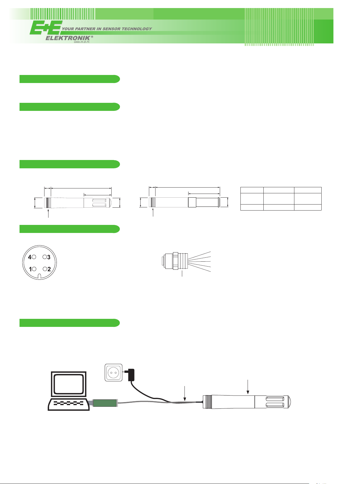
DIMENSIONS
polycarbonate housing - EE071-HTPx
13
8
(0.3”)
(0.51”)
M12x1
75 (3”)
34 (1.34”)
metal housing - EE071-HTMx
8
(0.3”)
(0.47”)
12
(0.47”)
M12x1
12
L
1
L
2
12
(0.47”)
Filter L
Stainless
steel grid
H2O
2
1
79.5 mm
(3.13“)
73.5 mm (2.89“) 33 mm (1.3“)
L
2
38.5 mm
(1.52“)
CONNECTION DIAGRAM
EE071:
1...+UB
2...B-RS485 (= Data-)
3...A-RS485 (= Data+)
4...GND
Front view
Important:
The metal enclosure of EE071-HTM shall not be connected to the ground (electrical isolation necessary). Alternatively, the GND of
the EE071 power supply shall be connected to the earth potential.
M12x1 ange (HA010705, Accessories)
brown...+UB
white.....B-RS485 (= Data-)
blue......A-RS485 (= Data+)
M16x1.5
black....GND
grey......shielding
SETUP AND ADJUSTMENT
The EE071 is ready to use and does not require any conguration by the user. The factory setup of EE071 corresponds to the type
number ordered. For ordering guide please see data sheet at www.epluse.com/EE071. If needed, the user can change the factory
setup by using the USB conguration adapter (code HA011012) and the EE-PCS, Product Conguration Software.
One can change the digital settings and perform RH and T adjustment.
EE071
PC
HA011012
EE-PCS PRODUCT CONFIGURATION SOFTWARE
1. Download the EE-PCS Product Conguration Software from www.epluse.com/congurator and install it on the PC.
2. Connect the E+E device to the PC using the appropriate conguration cable.
3. Start the EE-PCS software.
4. Follow the instructions on the EE-PCS opening page for scanning the ports and identifying the connected device.
5. Click on the desired setup or adjustment mode from the main EE-PCS menu on the left and follow the online instructions of the
EE-PCS.
Page 2

DIGITAL INTERFACE RS485 / MODBUS RTU
ID address, baud rate, parity and stop bits can be set via:
1. EE-PCS, Product Conguration Software and the appropriate conguration cable.
2. Modbus protocol in the register 60001 (0x00) and 60002 (0x01). See Application Note Modbus AN0103 (available on
www.epluse.com/EE071)
The EE071 factory setting for the slave-ID (Modbus address) is 247 as an integer 16 bit value.
The measured values are saved as a 32 bit oat value.
The serial number as ASCII-code is located at read register address 30001-30008 (16 bit per address).
The rmware version is located at register address 30009 (bit 15...8 = major release; bit 7...0 = minor release).
32Bit FLOAT (read register):
Function code +
Register number
30026 0x19 Temperature [°C]
30028 0x1B Temperature [°F]
30030 0x1D Rel Humidity [%]
30032 0x1F Abs Humidity [g/m³]
30034 0x21 Dew Point [°C]
30036 0x23 Dew Point [°F]
30038 0x25 Mixing ratio [g/kg]
(1)
[Dec]
Register address
[Hex]
(2)
Parameter
name
16Bit INTEGER (write register):
Function code +
Register number
(1) Register number starts from 1 3) Values are stored with a scaling of 1:100 (e.g.: 2550 is equivalent to 25.5°C)
(2) Register address starts from 0 4) Read function code: 0x03 Write function code: 0x10
5) Ambient pressure in mbar, with 2 decimal digits (e.g. 1008.25)
(1)
60001 0x00 Slave-ID
Register address
(2)
[Dec]
[Hex]
Parameter
name
16Bit INTEGER (read register):
Function code +
Register number
30040 0x27 Temperature [°C]
30041 0x28 Temperature [°F]
30042 0x29 Rel Humidity [%]
30043 0x2A Abs Humidity [g/m³]
30044 0x2B Dew Point [°C]
30045 0x2C Dew Point [°F]
30046 0x2D Mixing ratio [g/kg]
(1)
Register address
[Dec]
[Hex]
32Bit FLOAT (read & write register):
Function code +
Register number
5001
4)
(1)
Register address
(2)
[Dec]
[Hex]
0x1388 Air pressure
3)
(2)
Parameter
name
Parameter
name
5)
Example of MODBUS RTU command for reading the temperature (oat value) T = 26,652524 °C from the register 0x19
Device EE071; slave ID 247 [F7 in Hex]
Reference document, chapter 6.3: http://www.modbus.org/docs/Modbus_Application_Protocol_V1_1b.pdf
Request [Hex]: F7 03 00 19 00 02 EB 7B
Modbus ID
address
Request [Hex]: F7 03 00 19 00 02 EB 7B
Function
code
Starting
address Hi
Starting
address Lo
No. of
register Hi
No. of
register Lo
CRC
Response [Hex]: F7 03 04 38 5F 41 D5 0A E3
Modbus ID
address
Response [Hex]: F7 03 04 38 5F 41 D5 0A E3
Function
code
Byte count
Register 1
value Hi
Register 1
value Lo
Register 2
value Hi
Register 2
value Lo
CRC
For decoding of oat values (stored according standard IEEE754), please refer to AN0103, chapter 7.
Example
Response [Hex] Value in decimal
Byte 1
(Register 2 - Hi)
Byte 2
(Register 2 – Lo)
Byte 3
(Register 1 - Hi)
Byte 4
(Register 1 - Lo)
41 D5 38 5F 26.62524
NOTE:
The minimum accepted polling interval by device is 100 ms.
Please note the cycle of measuring of EE071 is one second:
• “measuring mode” = 250 ms. During this time the device read and process the parameters. Any request from master is refused
• “reading mode” = 750 ms. The data are available on register maps for reading from master.
Page 3

OUTDOOR USE
0.48
0.4
0.3
0.2
0.1
-0.1
-0.2
-0.3
-0.4
-0.48
-0.48
For outdoor applications EE071 must be used with the optional radiation shield HA010502.
Ø 105mm / Ø 4.13“
174mm / 6.85“
TECHNICAL DATA
(Modication rights reserved)
Measured values
Relative Humidity
Sensor element HCT01-00D
Modbus output range 0.00...100.00 % RH
Accuracy incl. hysteresis and nonlinearity ±2 % RH (0...90 % RH) ±3 % RH (90...100 % RH)
Temperature dependence < (0.025 + 0.0003 x RH) [% RH/°C]
Temperature
Sensor Pt1000
Modbus output range -40.00...+80.00 °C
Accuracy:
44mm / 1.73“
94mm / 3.7“
Ø0.2“
Ø5mm
0.79“
20mm
Standard
1.5mm
0.06“
122mm
4.8“
(-40...176 °F)
20mm
High
0.48
0.4
0.3
0.2
0.1
-0.1
-0.2
-0.3
-0.4
0.79“
44mm
1.73“
General
Supply voltage
Current consumption typ. 0.4 mA at a measuring rate of 1 sec.
Current pulse during power-up at UB 7 V: I
(with serial resistance 100 Ohm) at UB 12 V: I
Warmup Time after Power-Up max. 800ms
Interface / Bus RS485 / Modbus in slavemode
Housing / polycarbonate or stainless steel / IP65
Electromagnetic compatibility
FCC Part 15 Class B ICES-003 Issue 5 ClassB
Working and storage temperature -40...80°C
Max. cable length 100m (328.1ft)
1) For bus operation with terminal resistor (120Ω) min. UB: 4,5V DC
2) No terminal, pull-up or pull-down resistor integrated in the probe
3) EE071 is not protected against voltage spikes (surge)
1) 2)
4 - 28 V DC
3)
EN613226-1 EN61326-2-3
60 mA; current draw drops below 10 mA within 350 μs
max
110 mA; current draw drops below 10 mA within 400 μs
max
(-40...176°F)
MAINTENANCE
When employed in dusty, polluted environment:
• The lter cap shall be replaced as needed with an E+E original one. A polluted lter cap causes longer response time of the device.
Cleaning of the sensing head
• Use in polluted environment might arise the need for cleaning the sensing head and replacing the lter cap. In such a case please
see “Cleaning Instructions” at www.epluse.com/EE071.
Page 4

Calibration and adjustment
Depending on the application and the requirements of certain industries, there might arise the need for periodical humidity calibration
(comparison with a reference) or adjustment (bringing the device in line with a reference).
• Calibration and adjustment at E+E Elektronik
Calibration and/or adjustment can be performed in the E+E Elektronik calibration laboratory. For information on the E+E capabilities
in ISO or accredited calibration please see www.kalibrierdienst.at.
• Calibration and adjustment by the user
Calibrated salt solutions, please see „Calibration Kit - User Guide“ at www.epluse.com/EE071.
USA
FCC notice:
This equipment has been tested and found to comply with the limits for a Class B digital device, pursuant to part 15 of the FCC Rules.
These limits are designed to provide reasonable protection against harmful interference in a residential installation. This equipment generates, uses and can radiate radio frequency energy and, if not installed and used in accordance with the installation manual, may cause
harmful interference to radio communications. However, there is no guarantee that interference will not occur in a particular installation.
If this equipment does cause harmful interference to radio or television reception, which can be determined by turning the equipment off
and on, the user is encouraged to try to correct the interference by one or more of the following measures:
• Reorient or relocate the receiving antenna.
• Increase the separation between the equipment and receiver.
• Connect the equipment into an outlet on a circuit different from that to which thereceiver is connected.
• Consult the dealer or an experienced radio/TV technician for help.
CANADIAN
ICES-003 Issue 5:
CAN ICES-3 B / NMB-3 B
INFORMATION
+43 7235 605 0 / INFO@EPLUSE.COM
Langwiesen 7 • A-4209 Engerwitzdorf
Tel: +43 7235 605-0 • Fax: +43 7235 605-8
info@epluse.com • www.epluse.com
LG Linz Fn 165761 t • UID-Nr. ATU44043101
Place of Jurisdiction: A-4020 Linz • DVR0962759
BA_EE071_e // v1.2 // technical data are subject to change
 Loading...