

Page 1
MONTAGE- und BETRIEBSANLEITUNG
FEUCHTE / TEMPERATUR MESSUMFORMER
Type: SERIE EE04
INSTRUCTIONS for SETTING UP and OPERATING
HUMIDITY / TEMPERATURE TRANSMITTER
Type: SERIES EE04
ALLGEMEIN:
Messumformer der Serie EE04 sind für die Erfassung von Feuchte und Temperatur bestimmt.
Als Feuchtesensor wird ein hochgenauer, kapazitiver Sensor der Serie HC103 von E+E
verwendet.
Anwendung findet die Serie EE04 beispielsweise in Be- und Entfeuchtungsanlagen,
Trocknungsprozessen (z.B. Wäschetrockner), bei der Überwachung von Lagerräumen & feuchteempfindlichen Geräten (z.B.: Fotokopiermaschinen, Kühlschränken usw.) und auch bei
Fahrzeugklimaanlagen.
Bei Sonderanwendungen wenden Sie sich bitte an den Hersteller oder an Ihren zuständigen
Händler.
ACHTUNG:
Extreme mechanische und unsachgemäße Beanspruchungen sind unbedingt zu vermeiden.
Bei Wartungsarbeiten sind ESD Schutzmaßnahmen erforderlich.
REINIGUNGSHINWEISE:
- Filter keinem Druckwasser aussetzen
- Filter nur mit weicher Bürste reinigen
TECHNISCHE DATEN:
FEUCHTE
Arbeitsbereich 0...95%r.F. mit Coating 0...100%
Feuchtesensor HC103
Genauigkeit bei 25°C ± 3 %r.F. (40...60%r.F.) ± 5 %r.F. (0...95%r.F.)
Feuchteausgang linearer Analogausgang 0...100%r.F.
= 0,1 x U
z.B.:bei U
= 5VDC: 0...100%r.F. = 0,5V...4,5VDC
V
bis 0,9 x UV
V
30%r.F. = 1,7V
R
Last
> 5kOhm
TEMPERATUR
Temperaturausgang Spannungsteiler: NTC (10kOhm bei 25°C) mit
Pull down-Widerstand (10kOhm)
Betriebstemperatur -40...85°C
ALLGEMEIN
Versorgungsspannung (U
) 5VDC ±10%
V
Stromaufnahme typ. 1,4mA ohne Last am Ausgang
< 3,5mA mit maximaler Last amAusgang
Ansprechzeit τ63 bei 25°C < 45s
Schutzklasse Sensorseite: IP50 (mit Metallgitter Filter) Steckerseite: IP30
IP20 (ohne Filter)
Elektromagnetische Verträglichkeit EN61326-1 EN61326-2-3
Industrieumgebung
Achtung! Modul ist nicht gegen Stossspannungen (SURGE) geschützt!
GENERAL:
Transmitters of the EE04 series are designed to measure humidity and temperature. The
humidity sensor element is a capacitive sensor of the HC103 series from E+E.
Common applications for the EE04 transmitter are e.g. in the field of humidifiers and dehumidifiers, dryers, monitoring of storage rooms & humidity sensitve devices (e.g.: photocopiers,
refrigerators...) and also air conditioners for cars.
For special purpose applications please contact the manufacturer or your distributor.
ATTENTION:
Absolutely avoid extreme mechanical and improper strain.
For maintenance purposes it is recommended, to observe the valid ESD-safety precautions!
CLEANING NOTES:
- Do not clean filter with pressure water
- Clean filter with a soft brush only
TECHNICAL DATA:
HUMIDITY
working range 0...95%RH with coating 0...100%RH
humidity sensor element HC103
accuracy at 25 degC ±3 %RH (40...60%RH) ±5 %RH (0...95%RH)
humidity output linear analogue output 0...100%RH
= 0.1 x U
e.g.: at U
= 5VDC: 0...100%RH = 0.5V...4.5VDC
supply
to 0.9 x U
supply
supply
30%RH = 1.7V
R
Load
>5kOhm
TEMPERATURE
temperature output voltage divider: NTC (10 kOhm at 25degC /
77°F) and
pull down-resistor (10kOhm)
operating temperature -40...85degC (-40...185°F)
GENERAL
supply voltage (U
) 5VDC ±10%
supply
supply current typ. 1.4mA without load at output
< 3.5mA with maximum load at output
response time τ
at 25°C (77°F) < 45s
63
protection class sensor side: IP50 (with metal grid filter) connector side: IP30
IP20 (without filter)
Electromagnetic compatibility EN61326-1 EN61326-2-3
Industrial Environment
Attention! The module has no protection against surge voltages!
BA_EE04_06 // Technische Änderungen vorbehalten // 302228 OM_EE04_06 // technical data are subject to change
Page 2
SELBSTHILFE bei FEHLERN:
Fehler mögliche Ursache Maßnahme
unrealistische Werte nicht optimale Montage Achten Sie darauf, dass der Fühler kopf
die gleiche Temperatur wie die zu messende
Luft besitzt.
zu lange Ansprechzeit Verschmutzung des Filters Filtertausch bzw. Reinigung
Falsche Filtertype Filtertype auf die Anwendung anpassen
Ausfall des Gerätes keine Versorgungsspannung Zuleitung und Versorgungsspannung
überprüfen
zu hohe Feuchtewerte Betauung im Fühlerkopf Fühlerkopf trocknen; evtl. Filter wechseln
SELF-HELP in case of ERRORS:
error possible cause remedies
unrealistic values wrong installation Please take care that the ambient tempe rature of the transmitter is the same like
the measuring temperature.
long response time pollution of the filter change filter cap
wrong filter type adjust filter type to application
complete failure of the no supply voltage check supply cable and supply voltage
instrument
humidity values too high bedewing of the sensor probe dry the sensor probe and if necessary
replace the filter
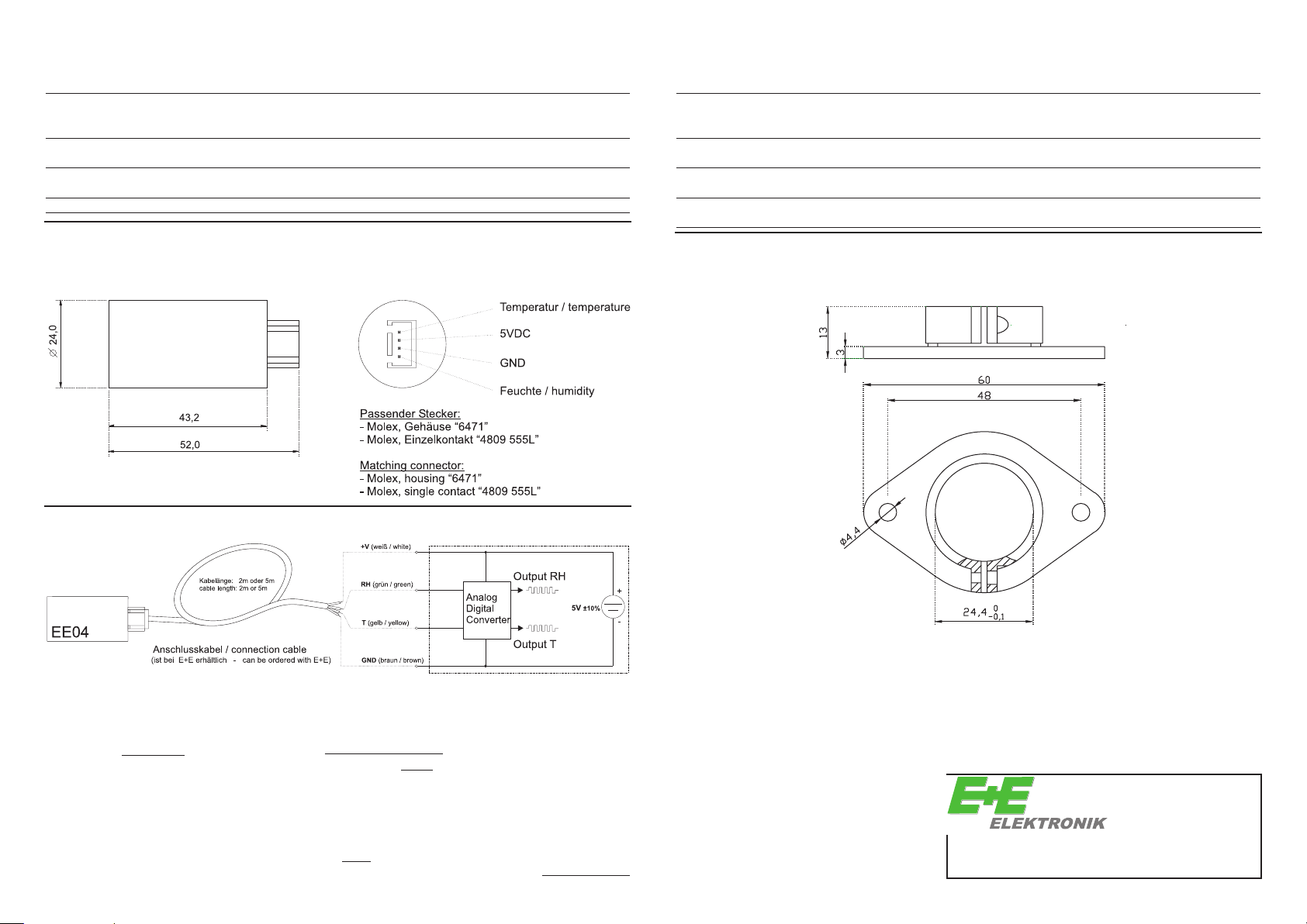
Abmessungen (mm) / dimensions (mm) Anschluss / connector
1 mm = 0.03937” / 1” = 25.4 mm
Anschlusskabel & Belegung Connection cable & assignement
(6.56ft or 16.4ft)
Berechnung T
bei Calculation T
[°C]
out of
[°C]
gegebener Ausgangsspannung output voltage
10000 x U
R
=
NTC
V
Out
- 10000
U
T
=
[K]
11,726 + ln
3496
(
R
NTC
10000
T
= T
- 273,15
[K]
[°C]
)
Berechnung der Ausgangsspannung Calculation output voltage
bei gegebener T
T
= T
[°C]
+ 273,15
[K]
[°C]
3496
R
NTC
= 10000 x e
(
- 11,726
T
[K]
)
U
Out
=
out of T
10000 x U
R
( )
NTC
[°C]
+ 10000
v
Befestigungsflansch Mounting flange
[Maße in mm]
[measures in mm]
1 mm = 0.03937” / 1” = 25.4 mm
Langwiesen 7
A-4209 Engerwitzdorf
Austria
T: +43-7235-605-0 F: +43-7235-605-8
info@epluse.com www.epluse.com
 Loading...