


DW20
DW10
For your personal safety,
READ and UNDERSTAND before using.
SAVE THESE INSTRUCTIONS FOR
FUTURE REFERENCE.

Hose
Sanding Head
D-Handle(Optional)
Sponge
Brush Cap
Speed Adjustor Thumb Wheel
Model DW20 DW10
Length 1540mm (Long-Reach type) 1090mm (Compact type)
Voltage 115V / 60Hz or 230V /50Hz
No load speed 650 ~1600/min 650 ~1600/min
Full load speed 280 ~ 950/min 280 ~ 950/min
Power input 550W 550W
Sanding disc diameter 225mm 225mm
Net weight 4.7 kg (10 lbs.) 3.8 kg (8.4 lbs)
On/Off Switch
Soft Grip
Vacuum Swivel Mount
Hose Protection Device
(Optional)
2

GENERAL SAFETY RULES
W A R N I N G ! Re ad a n d u n d e r s t a n d all
instructions. Failure to follow all instructions
listed below, may result in electric shock, fire
and / or ser ious pe rsona l injur y. The term
“p ower tool ” in all of the war nings liste d
b elo w re f e r s to your ma in s -ope ra t ed
(corded) power tool.
SAVE THESE INSTRUCTIONS.
Work area safety
Ke ep your work are a clean and we ll lit.
Cluttere d worksite s and dar k areas invite
accidents.
Do not operate power to ols in explo si ve
atmos phere s, such as in the prese nce of
flammable liquid, gases, or dust. Power tools
create sparks which may ignite the dust or
fumes.
Keep bystanders, children, and visitors away
while operating a p ower tool. Distractio ns
can cause you to lose control.
Electrical Safety
Groun ded too ls must be plugged into an
outlet properly in stalled and grounded in
accordance with all codes and ordinances.
Nev er re mo v e th e gr oun d in g pro ng or
modify the plug in any way. Do not use any
ada pto r pl ugs . Che ck w ith a qu a li f ie d
electrician if you are in doubt as to whether
the outlet is properly grounded. If the tools
sh ou ld electricall y mal function or bre ak
down, grounding provides a low resistance
path to carry electricity away from the user.
Avoid body contact with grounded surfaces
s uch as pi p e s , radi a t o rs, ra ng e s a nd
refriger ators. The re is an incr eased risk of
electric shock if your body is grounded.
Do n’ t exp os e p ow er tools to rain or we t
conditions. Water entering a power tool will
increase the risk of electric shock.
Don’t abuse the cord. Never use the cord to
carry the tools or pull the plug from an outlet.
Keep cord away from heat, oil, sharp edges
or moving parts. Replace damaged cords
immediately. Damaged cords increase the
risk of electric shock.
When operating a power tool outside, use an
outdoor extension cord mar ked “W-A” or
“W.” These cords are rated for outdoor use
and reduce the risk of electric shock.
Personal Safety
Stay alert, watch what you are doing and use
co mmon sense when ope rating a pow er
tool. Do not use tool while tired or under the
influence of drugs, alcohol, or medication. A
momen t of in at ten ti on whi le ope ra ting
power to ols may result in seriou s personal
injury.
Us e safety equipment . Always we ar eye
protection. Safety equipment such as dust
mask, non-sk id safety shoes, har d hat, or
3

he aring protect ion us ed for appro pr iate
conditions will reduce personal injuries.
preventive safety measures reduce the risk of
starting the tool accidentally.
Avoid accidental starting. Be sure switch is
off before plugging in. Plugging in tools that
have the switch on invites accidents.
Remove adjusting keys or switches before
turning the tool on. A wrench or a key that is
left attached to a rotating part of the tool
may result in personal injury.
Do not overreach. Keep a proper footing and
ba lance at all times. Prope r fo oting and
balance enables better control of the tool in
unexpected situations.
Dress properly. Do not wear loose clothing or
jewelry. Keep your hair, clothing and gloves
aw ay from movin g par ts . Loose clo th es ,
jewelry or long hair can be caught in moving
parts.
Tool use and care
Do not force tool. Use the co rre ct to ol fo r
your application. The correct tool will do the
job better and safer at the rate for which it is
designed.
Do not use tool if switch does not turn it on or
off. Any tool that cannot be controlled with
the sw i t ch is da n g ero us a n d mus t be
repaired.
Disconnect the plug from the power source
before making any adjustments, changing
acc e s sor i es, or s tor i n g the to ol. Su c h
Store idle tools out of reach of children and
do not al low pe rs ons un fa mi liar wit h the
power tool or these instructions to operate
the power tool. Tools are dangerous in the
hands of untrained users.
Maintain tools with care. Properly maintained
tools are less likely to bind and are easier to
control.
Check for misalignment or binding of moving
pa rt s, breakage of par ts , and any ot her
condition that may affect the tools operation.
If damaged, have the tool serviced before
using. Many accidents are caused by poorly
maintained tools.
Use the power tool, accessories and blades
etc., in accordance with these instructions
and in the manner intended for the particular
type of power tool, taking into account the
worki ng con di tio ns and th e wo rk to be
per f orm ed. Us e of th e pow e r to o l fo r
opera tions different from th ose intended
could result in a hazardous situation.
Service
Have your tool serviced by a qualified repair
person usin g on ly identica l re place ment
parts. This will ensure that the safety of the
power tool is maintained.
-WARNING- To reduce the risk of injury, user
must read instruction manual.
4

Symbols used in this manual
V……..volts
A……..amperes
Hz……hertz
W……..watt
~………alternating current
n0………no load speed
/min……..revolutions or reciprocation per
minute
………….class II tool
SPECIFIC SAFETY RULES
1. Keep hands away from rotating sanding
head area at all times!
2. Prolonge d breathing of ai rborne dust
f rom d rywa ll sa nd i n g m a y e f f e ct
respiratory function:
Al way s use a vacuum clea ner with a
bag approved for drywall dust installed.
Always wear a respirator approved for
dust and mist.
3. Sanding LEAD-BASED paint is extremely
toxic and should not be attempted. Only
allow professionals with special training
and equipment perform this task.
4. Maintain proper footing and balance at
all times. Do not overreach. Use proper
scaffolding
5. A l w a y s we ar a p p r o p r i a t e sa fety
equipment when operating.
6. Importan t: After com ple ting sanding,
switch off the switch and wait for the
c o a st i n g s a n di n g h e a d t o s t o p
co mpl et ely be fo re p ut ting t he tool
down.
7. Never operate the tool in an area with
flamm abl e soli ds , li qui ds , or gases .
Spark s from the commuta tor/carb on
brushes could cause a fire or explosion.
8. There are certain applications for which
t h i s t o o l w a s d e s i g n e d . T h e
manufacturer strongly recommends that
this tool NOT be modified and/or used
for any application other than for which
i t w as desi g n e d. If you hav e an y
questions relative to its application DO
NOT use the tool until you have written
the m anu f act u rer a nd ha v e be e n
advised.
9. Use the machine with both hands at all
t imes. Loss of c ontro l can cause
personal injury.
10. Keep power supply cord clear from the
working range of the machine. Always
lead the cable away behind you.
11. Immediately switch off the machine if
u n u s u a l v i b r a t i o n s o r i f o t h e r
malfunctions occur. Check the machine
in order to find out the cause.
12. The dust that arises when working with
this tool can be harmful to health. Use a
du st absorpt io n sys tem and wea r a
sui tab le dust p ro t ec tio n mas k an d
remove deposited dust with a vacuum
cleaner.
FUNCTIONAL DESCRIPTION
This Elec tr ic D ry wal l Sand er i s spec ia lly
designed for the most efficient sanding of
drywall or plaster walls and ceilings for both
new construction and renovation work. It is
5

de signed t o w or k in conjun ct io n with a
vacuum cleaner for minimum dust and best
sanding results. The pivoting sanding head
allows excellent results with minimum time
and effort.
Electrical connection
The netw ork voltage must confo rm to the
voltage indicated on the tool name plate.
Under no circumstances should the tool be
use d w hen t h e po w er su p ply ca ble is
dam ag ed. A da mag ed c abl e mu st be
re pl ac ed immediate ly by an aut ho ri ze d
Customer Service Center. Do not try to repair
th e da ma ged cable yoursel f. The use of
da maged power ca bles can lead to an
electric shock.
● UNPACKING
Carefully remove the tool and all loose items
from the shipping container.
Retain all packing materials until after you
have inspected and satisfactorily operated
the machine.
● CARTON CONTENTS
1. Drywall Sanding Machine
2. Vacuum cleaner hose
3. Instruction manual
DO NOT OPERATE THIS TOOL UNTIL YOU READ
AND UNDERSTAND THE ENTIRE INSTRUCTION
MANUAL
Extension cable
If an extension cable is required, it must have
a sufficient cross-section so as to prevent an
excessive drop in voltage or overheating. An
excessive drop in voltage reduces the output
and can lead to fail ure of the moto r. The
following table shows
you the correct cable diameter as a function
of the cable length for this machine. Use only
U.L. and CSA listed extension cables. Never
use two extension cables together. Instead,
use one long one.
Total Extension Cord Size (AWG)
Cord Length (feet)
25 16
50 12
100 10
150 8
200 6
● To install a sandpaper disc:
1. Unplug the machine.
2. Peel away the worn out sandpaper disc,
le av ing the sp onge ba cking pad in
place.
3. Ca refully cent er the new sandpa per
disc and press into place. It will be held
securely by the hook and loop backing.
● To replace the Hook and Loop Sponge Pad:
The sponge pad must be perfectly flat to get
go od sanding resu lt s. If it is def ormed or
damaged it will cause very uneven sanding.
Always replace it when damaged. It is hook
and loop on both sides, so to Replace it, peel
it aw ay from the ho ok an d loo p on the
6

Sanding Plate Base and, taking great care to
keep it perfectly centered, affix a new one.
● Th e Br us h Br ist les on t he edg e of the
Sanding Plate Cover:
The brush bristles on the edge of the Sanding
Plate Cover serve two purposes, they keep
the sanding disc properly aligned with the
work surface without gouging and they also
help the efficiency of the dust collection by
the vacuum cleaner. These brush bristles will
wear with continued use.
The Sanding Plate Cover should be replaced
when the bri stles are too worn to ensur e
effective dust collection and stabilization of
the sanding head.
To replace the cover, follow these steps:
Th en , pre ss the cover down aga in st th e
spring and, using snap-ring pliers, remove the
circlip which holds the sanding plate cover
to the bracket.
Finally, carefully work the vacuum hose free
then lift sanding plate cover away.
Replacem ent is the oppos ite of removal.
Don’t forget the spring. Entrust all repairs to
an authorized service center.
Hold the sanding plate in one hand and with
the other, using the L-hex wrench (supplied),
first break free the center bolt clockwise (1/8
turn only!).
Then only use the L-hex wrench to hold the
center bo lt from turning and spi n of f the
sanding plate counterclockwise.
● To install the vacuum cleaner hose:
1. Unplug the machine.
2. Plug the vacuum cleaner hose bayonet
mount into the swivel mount in the back
7

of the machine. Once the tangs of the
bayonet mount are fully inserted in the
slots, hold the swivel mount from turning
and t urn the h ose b ay o net m ou n t
clockwise to lock.
3. Removal is the opposite of assembly.
● The vacuum cleaner:
Ensure that you have a bag installed in your
va cuum cleaner which is ap proved and
rated for drywall dust.
power circuit.
● Switching the machine on and off
To switch on:
Wh il e holding with the left ha nd on th e
co lu mn and th e right han d on th e main
handle, Press the rocker switch to the right
with the thumb of the right hand. Anticipate
and be ready for the start up torque when
the machine first starts.
To switch off:
Press the rocker switch to the left. After the
machine has been switched off, the sanding
disc will still rotate for a time. Take care that
parts of your body do not come into contact
with the disc and do not set the machine
down while it is still rotating!
On/Off Switch
WARNING: Failure to use an approved dust
bag in your vacuum will increase the level of
air borne dust in the work area. Prolonged
exposure to such dust may cause respiratory
harm.
● STARTING AND STOPPING TOOL
Make sure that the power circuit voltage is
the same as that shown on the specification
pl at e of the mac hi ne and th at sw itch is
“OFF” befor e co nnect ing the tool to the
● Adjusting the rotation speed:
The speed of the machine is variable to suit
different tasks. It can be adjusted from 650/
mi n up to 1600/m in by us in g the th um b
wh eel. Using the rig ht thu mb, tu rn in the
downward (counterclockwise) direction to
incre ase th e sp ee d an d in th e up wa rd
(clockwise) direction to decrease the speed.
8

Generally, you should use the higher speed
02
03
04
05
02
01
for fast stock removal and the lower speed
for more precise control.
Speed Adjustment
HOW TO USE THE TOOL
Effective control of this powerful saw requires
two-handed operation for maximum safety
and control.
The proper hold is to keep one hand on the
ma in han dle and th e ot he r ha nd on the
spo ng e gr ip o n th e colu mn. It is vita lly
important to keep stable footing at all times,
especially when standing on scaffolding or
stilts.
■ MOUNTING THE OPTIONAL BAIL HANDLE:
1. Lo osen the 2 thu mb scr ews (05) and
remove the clamp cap (04).
2. Place the handle in the desired position
on the column.
3. Clamp the handle in place by replacing
the clamp cap and tight ening the 2
thumb screws.
● SANDING OPERATIONS
1. O n c e th e m a c h i ne a n d vacuum
clea n e r are se t u p a nd all sa f ety
measures and equipment are in place,
begin by turning on the vacuum cleaner
and then the machine. (If you are using
a va cuu m cl ea ner wit h in teg ra ted
switching, then simply turn the machine
on.)
2. Begin sanding and carefully contact the
work surface as lightly as p ossible-just
enough to keep the sanding head flat
against the surface.
3. The joints in the sanding head allow the
sanding disc to follow the contours of
the work surface.
4. The best technique is to use overlapping
sweeps and keep the head in constant
motion. Never stop too long in any one
place or there will be swirl marks. With
experience it will be very easy to create
excellent results.
NOTE: Ensu re that the sandpaper yo u are
using is suited to the task. Overly coarse grit
9

paper may remove material too quickly to
control. While overly fine grit paper may clog
too often and not shape down the surface.
CAU T ION : Tak e c ar e t o av o id po i nt e d
projections and nails, etc. This will wipe out
the sandpaper and probably damage the
sponge pad as well.
MAINTENANCE
● KEEP TOOL CLEAN
Periodically blow out all air passages with dry
compressed air. All plastic parts should be
cleaned with a soft damp cloth. NEVER use
solvents to clean plastic parts. They could
possibly dissolve or otherwise damage the
material.
Wear safety glasses while using compressed
air.
Clean the vacuum swivel connector as too
much dust will keep it from turning freely.
● THE CARBON BRUSHES
The carbon brushes are a normal wearing
part and must be replaced when they reach
their wear limit. When the brushes are worn to
a length of 1/4", they should be replaced.
NOTE: Checking and replacing the carbon
brushes should be entrusted to a qualified
service center.
TO CHANGE THE BRUSHES
1. Unplug the machine.
2. Remove the brush cap with a slothead
screwdriver
3. Remove the brush.
4. Install new brushes in reverse order and
replace covers
Brush Cap
If the replacement of the power supply
cord is necessary, this has to be done
by the manufacturer or their agent in
order to avoid a safety hazard.
10
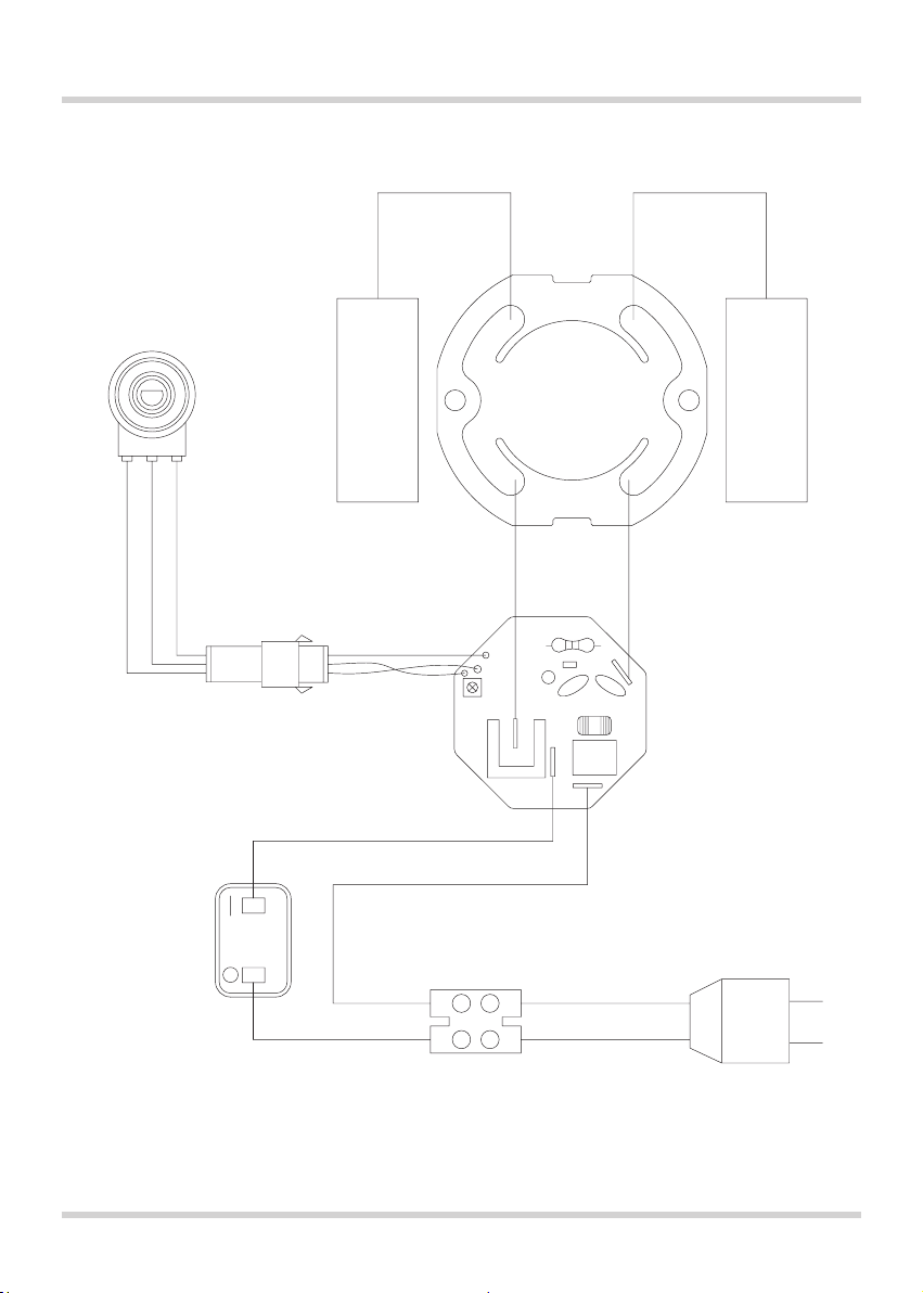
WIRING
BLACK
RED
WHITE
CARBON
BRUSH
OVERLOAD
SPEED
CONTROL
UNIT
MOTOR
CARBON
BRUSH
BLACKBLACK
RED
SWITCH
TERMINAL
AC
BLACK BLACK
AC
11

EXPLODED VIEW
01 02
08
03 04
25
26
27
28
26
29
30
71
39
34
31
35
39A
40
40A
64
65
66
67
68
69 70
31
44
51
53
09
12
13
10
11
19
18
75
05
32
33
38
38A
45
49
57
23
24
06
36
37
41
42
43
72
57
60
61
62
OPTIONAL
73
74
63
14
15
16
75
18
19
07
20
21
22
23
48
47
46
52
57
58
57
59
A3
A2
A1
12

PARTS LIST
No. Parts Name Q'TY
1 POWER SUPPLY CABLE 1
2 CORD ARMOR 1
3 VACUUM EXTENSION HOSE 4M 1
4 QUICK RELEASE HOSE CONNECTOR 1
5 SCREW M4 x 16 6
6 RIGHT HANDLE COVER 1
7 LEFT HANDLE COVER 1
8 CABLE CLIP 1
9 SCREW M4 x 14 2
10 SCREW M4 x 25 2
11 SPEED CONTROL 1
12 WIRE CONNECTOR 1
13 WIRE LEADER 1
14 WIRE LEADER 1
15 WIRE LEADER 1
16 MOTOR SWITCH 1
17 N/A -
18 CARBON BRUSH 2
19 CARBON BRUSH HOLDER 2
20 MOTOR HOUSING 1
21 STATOR 1
22 STATOR SCREW M4 x 50 2
23 BALL BEARING 608 2RS 2
24 ARMATURE 1
25 GEAR PLATE 1
26 BUSHING 6 x 10 x 8 3
27 INTERMEDIATE GEAR 1
28 INTERMEDIATE GEAR PINION 1
29 INTERNAL CIRCLIP S-8 1
30 OUTPUT GEAR 1
31 SCREW M5 x 10 4
32 GEAR CASE 1
33 SCREW W/ WASHER M4 x 30 3
34 INTERNAL CIRCLIP S-10 1
35 BALL BEARING 6200 2RS 1
36 WOODRUFF KEY 3 x 8 1
37 SPINDLE 1
38 FIRST DRIVE SHAFT 254mm 1
38A FIRST DRIVE SHAFT 704mm 1
39 EXTENSION COLUMN 577.3mm 1
39A EXTENSION COLUMN 1027.3mm 1
No. Parts Name Q'TY
40 FOAM HANDLE GRIP 1
40A FOAM HANDLE GRIP 1
41 SHAFT CONNECTOR 1
42 BALL BEARING 6001 2RS 1
43 INTERNAL CIRCLIP S-12 1
44 SCREW M4 x 20 4
45 RIGHT DRIVE COVER 1
46 LEFT DRIVE COVER 1
47 SECONDARY DRIVE SHAFT 1
48 DRIVE SHAFT COVER 1
49 HOLDING PIN 6 x 39 1
50 N/A -
51 RIGHT SANDER BRACKET 1
52 LEFT SANDER BRACKET 1
53 SCREW M4 x 8 2
54 N/A -
55 N/A -
56 N/A -
57 SCREW M5 4
58 PIVOT BASE 1
59 PIVOT CONNECTING BRACKET 1
60 CONNECTING SPINDLE 1
61 BALL BEARING 6002 2RS NSK 1
62 EXTERNAL CIRCLIP R-32 1
63 SPRING ø2 x ø49 x 40L x 4T 1
64 VACUUM HOSE 1
65 SPRING ø1 x ø32 x 363L x 30T 1
66 PLASTIC CLIP 1
67 SANDING PLATE COVER 1
68 INTERNAL CIRCLIP S-40 1
69 SANDING PLATE BASE 1
70 VELCRO SPONGE PAD 1
71 EXTERNAL CIRCLIP R-30 1
72 DUST GUIDE 1
73 SHAFT RACE M14 x ø20 x 6.5 1
74 RADIAL SHAFT SEAL ø20 x ø32 x 5 1
75 BRUSH CAP 2
Optional
A1 RIGHT HOSE SUPPORT 1
A2 LEFT HOSE SUPPORT 1
A3 SCREW M4 x 14 4
13

London Dublin
Aristospray UK, Granville House Aristospray, Unit 45
Wallingford Road, Uxbridge Baldoyle Industrial Estate
Middlesex UB8 2RW Baldoyle, Dublin 13
T +44 (0) 1895 276751 T +353 (0) 1 806 3003
F +44 (0) 1895 276755 F +353 (0) 1 806 3075
E sales@aristospray.com E sales@aristospray.ie
W www.aristosprayuk.com
 Loading...