

Page 1
5531M and 5531MV Series
Adaptatone Installation Sheet
WARNINGS
• Explosion hazard. Do not disconnect equipment unless power has
been removed or the area is known to be nonhazardous.
• Explosion hazard. Substitution of any components may impair
suitability for Class I, Division 2.
• To ensure integrity of the Adaptatone assembly when adjusting the
speaker direction, make sure threads in the enclosure remain fully
engaged and do not turn speaker more than 360 degrees from the
original factory installed position.
• To prevent fire, shock, and component damage, no work, including
circuit board removal, should be performed while the circuit is
energized.
• High voltage is present when the product is energized.
• High volume may cause harm to personnel in close proximity.
To ensure integrity of the enclosure:
• Be sure that the cover gasket, P/N P-007549-0069, is adhered into
the groove at the cover perimeter before replacing the signal box
cover.
• Be sure that the four collar gaskets, P/N P-041930-0362, are in
place on each cover screw before securing the signal box cover.
• When securing the cover, start the screws by hand, making sure
that they are threaded into the tapped holes in the housing bosses
before securing them with a screwdriver. Torque the signal box
cover screws to a minimum of 20 in-lbs. This ensures the required
tight fit.
Description
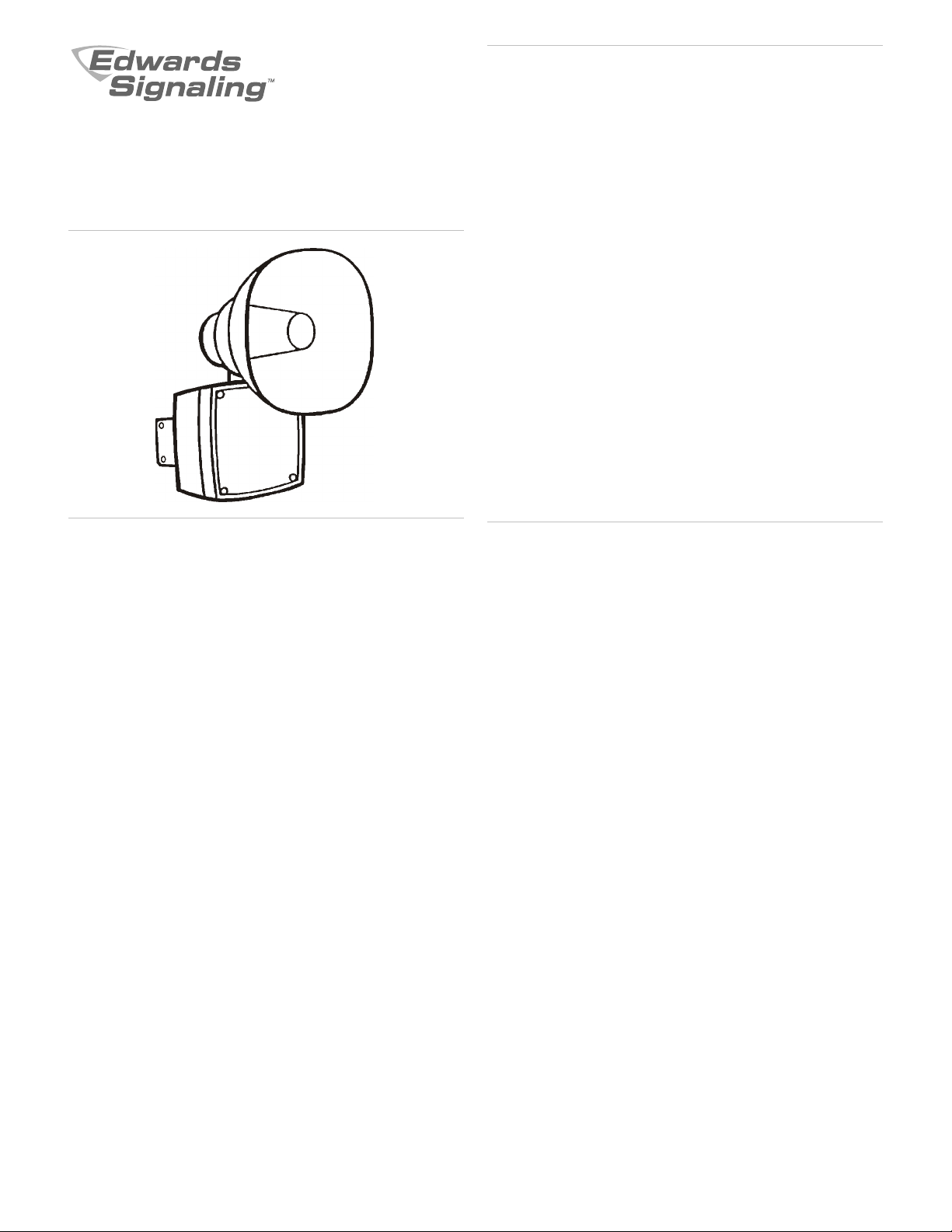
The 5531M and 5531MV Series Adaptatone signals are intended for
industrial applications where high audible output and microcomputer
reliability are required. The 5531M and 5531MV Series (Adaptatone
Millennium) are for indoor/outdoor use, and are UL and cUL Listed as
Audible Signal Appliances for use in the hazardous locations listed in
Table 1.
The device operates from local power. It accommodates up to four
normally-open contacts on its inputs. The tone that sounds in response
to an active input is determined by setting miniature programming
switches inside the unit. Table 6 shows the switch settings for the
available tones.
Four tones may be programmed into the unit at any time. These tones
operate on a pyramid-type priority system. The tone programmed on
SW1 overrides the tones programmed on SW2, SW3, and SW4. The
tone on SW2 overrides the tones programmed on SW3 and SW4.
Likewise, the tone on SW3 overrides the tone programmed on SW4.
The tone programmed on SW4 has the lowest priority and cannot
override any other programmed tone.
The speaker direction and the output level are easily adjustable.
This equipment is suitable for use in Class I, Division 2, Groups A, B,
C, and D; Class II, Division 2, Groups F and G; Class III hazardous
locations or nonhazardous locations.
Installation
The device may be mounted on any flat surface or may be used as a
freestanding unit mounted on a rigid pipe. The Adaptatone must be
installed in accordance with the latest edition of the National Electrical
Code or other regulations applicable to the country and locality of
installation and by a trained and qualified electrician.
For model numbers ending in AQ, 24 VAC power must be transformer
isolated from mains or line power.
Note: Any kind of service or maintenance performed while the unit is
energized will void the warranty.
To install the Adaptatone:
1. Mount the Adaptatone as shown in Figure 1.
Flat Surface mounting: Secure the unit to the mounting surface
using the four mounting holes in the mounting plate on the rear of
the box. Use the #10 × 3 wood screws (furnished loose) or other
hardware (not supplied) suitable for the mounting surface.
Rigid Pipe mounting: Loosen the four cover screws from the
signal box and lift off the signal box cover.
Note: The cover screws are captive. Do not remove them from the
cover.
Remove the center knockout in the lower wall of the box and
mount the box on a 1/2 in. conduit pipe using a suitable connector.
2. Wire in accordance with the instructions in “Wiring” on page 2.
3. Refer to Figure 5 and Table 6 and select the desired tones. Set the
miniature programming switches on the input board.
For input connected to IN1, set on SW1; IN2, set on SW2; IN3, set
on SW3, and IN4, set on SW4, in order of priority desired.
4. Adjust volume level, if desired, by turning the potentiometer
located on the main board (Figure 5 and Figure 6).
5. Tightly secure the signal box cover using four retained cover
screws.
6. Torque signal box cover screws to a minimum of 20 in-lbs.
7. To adjust speaker direction, loosen the large star nut (Figure 1)
and turn the speaker to the approximate desired position.
Retighten the nut and turn the speaker slightly clockwise until it is
locked into place.
Regardless of speaker direction adjustment, it is important that the
star nut be tightened wrench tight to ensure that the speaker
position is maintained securely.
8. Verify operability.
P/N 3100008-EN • REV 06 • ISS 14JAN15 1 / 8
Page 2
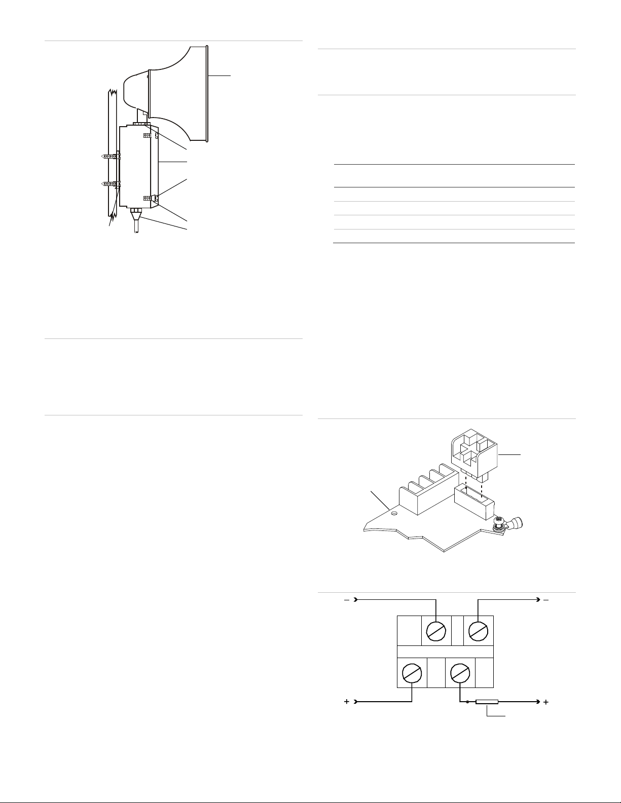
Figure 1: Adaptatone mounting
(1) Speaker
(2)
(3)
(4)
(5)
(6)
(7) #10 × 3 screws or hardware suitable for the mounting surface
Message
location
1
2
3
4
(1) Terminal block (TB1)
(2) Main board
(1) To internal power supply (factory installed)
(2)
(3) To optional 24 VDC battery backup
(1)
(2)
(3)
(4)
(5)
(6)
(7)
2
4
1
3
(1)
(2)
(1) (3)
2
1 3
4
(2)
Recording a voice message (5531MV series)
WARNINGS
• High voltage is present when product is energized.
• High volume may cause harm to personnel in close proximity.
To record a message:
1. Put switches A and B on the programming DIP switch in the proper
position for the message to be recorded (Figure 6). For
programming a message longer than five seconds, use message
location 1.
0 Sec CLOSED CLOSED
5 Sec OPEN CLOSED
10 Sec CLOSED OPEN
15 Sec OPEN OPEN
Start Switch A
settings
Switch B
Settings
Large star nut to adjust speaker direction
Signal box
Cover screws (4X)
Collar gaskets (4X)
Raceway and connections (not supplied) to 1/2 in. knockout hole
Wiring
WARNINGS
• To prevent fire and shock, wire the Adaptatone only as described
on this installation sheet.
• When wiring units with replaceable fuses, ensure that an adequate
switch, suitable for the location, is provided to remove power from
the fuse. Remove power before servicing the fuse.
Note: Terminal Block TB1 can be unplugged from the main board to
complete wiring as shown in Figure 2 and Figure 3.
To wire the Adaptatone:
1. Install wires through a knockout hole in the bottom of the box from
a raceway that is, with its connections to the 1/2 in. conduit
knockout hole, approved for the same degree of protection and
enclosure type needed by the application. Use the provided plastic
cable wrap, on the barrier to the electronics, to separate incoming
power leads from signal and tone initiating leads, per NEC
(Figure 4).
2. Wire as follows referring to Figure 4.
If Edwards Signal Actuator model number 5538-4 is used to
manually initiate tones, connect its four normally-open switches to
the tone generator as shown on the instructions provided with the
Signal Actuator unit.
a. Connect the green and yellow-striped earth ground wires to
earth ground.
b. Select the appropriate method for wiring to the input board
from Figure 7 through Figure 11 for models with 24 V input
boards and Figure 12 and Figure 13 for models with 120 V
input boards.
c. Connect incoming power to wire leads using a butt splice or
other method listed, certified, or otherwise approved by local
authorities. Leads are both black for -AQ and -N5 models and
are black and white for -Y6 models.
d. Optional. Connect an external 24 VDC battery (not supplied) in
2 / 8 P/N 3100008-EN • REV 06 • ISS 14JAN15
series with the separate diode assembly P/N 2600010
(supplied) to TB1 terminals 3 and 4 on the main board as
shown in Figure 3 and marked on the diode assembly.
2. Put switch PGM on the programming DIP switch in the CLOSED
position for programming mode (Figure 6).
3. Press and hold the record button while speaking clearly into the
microphone to record your message. Release the button when
recording is complete.
4. To test the message, press and hold PLAY while in programming
mode.
Note: This will play only the current location.
5. Adjust the volume as necessary. Set the main volume using the
potentiometer on the main board (Figure 5 and Figure 6), and then
set the voice volume using the potentiometer on the voice module
board (Figure 6).
Figure 2: Terminal block TB1
Figure 3: Wiring to terminal block TB1 input circuit
Diode assembly P/N 2600010
Page 3
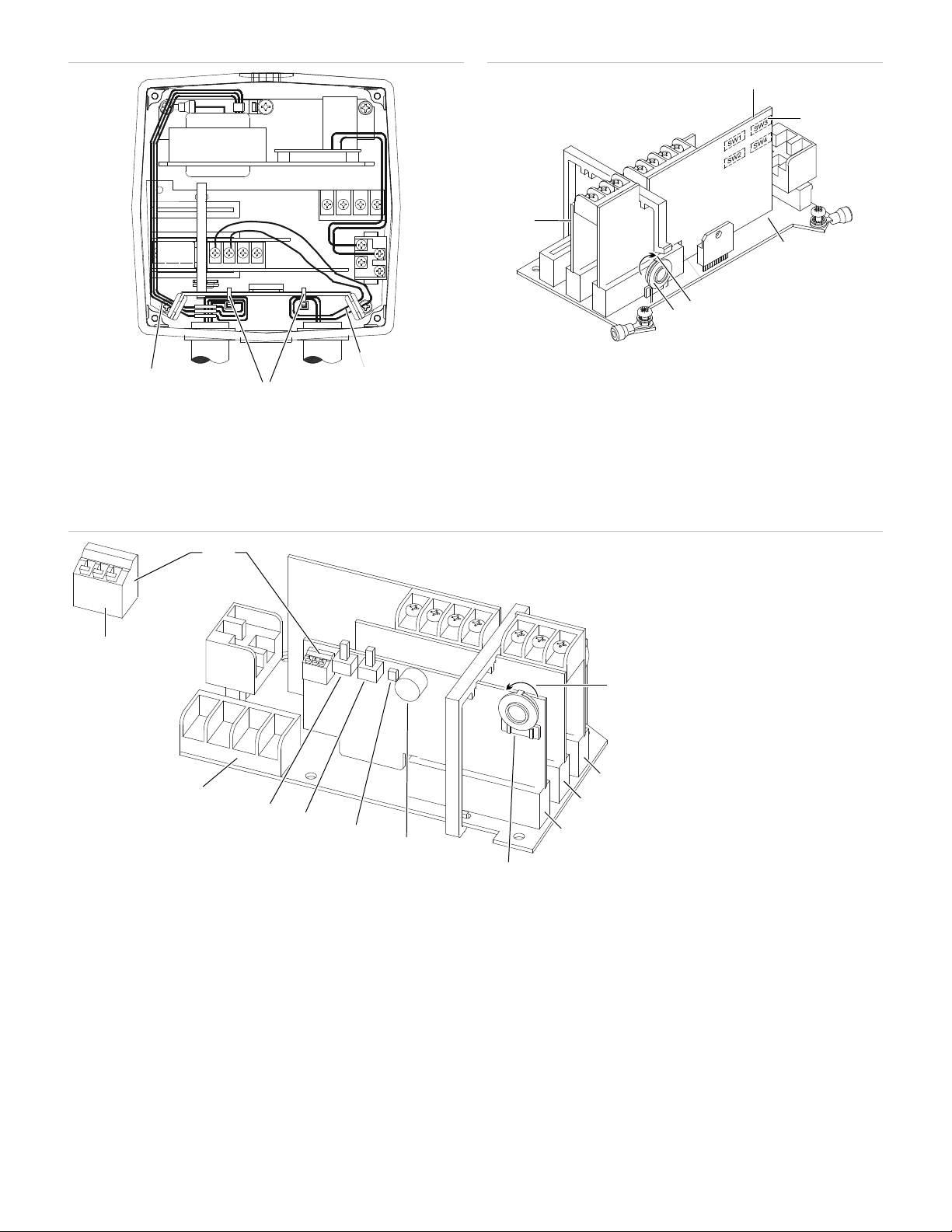
Figure 4: Wiring the Adaptatone
(1) Power and earth ground leads
(2)
(3) Signal/Tone initiating leads to be connected to the input board
(1) Input board
(2)
(3)
(4)
(5)
(6) Processor board
(1)
(2)
(3)
(4)
(5)
(6)
(7)
(8)
(9)
(10)
(11)
(12)
(1)
(2)
(3)
IN4
N
+VS
GND
IN1
IN2
IN3
(1)
(2)
(3)
(4)
(5)
(6)
A
B
PGM
(1)
(2)
(3)
(4)
(5)
(6)
(7)
(8)
(9)
(11 )
(12)
(10)
Plastic cable wrap (provided) used to separate power leads from
signal and tone initiating leads
Figure 5: PC board locations
Programming switches (other side)
Main board
Direction of increasing volume
Potentiometer for volume adjustment
Figure 6: PC board locations (voice messaging models)
P/N 3100008-EN • REV 06 • ISS 14JAN15 3 / 8
Direction of increasing volume
Input board
Processor board
Voice module board
Voice module potentiometer for
volume adjustment
Microphone
Record LED
Play
Record
Terminal block TB1
Programming DIP switch. Switches
are shown in OFF (down) position.
Programming DIP switch
Page 4
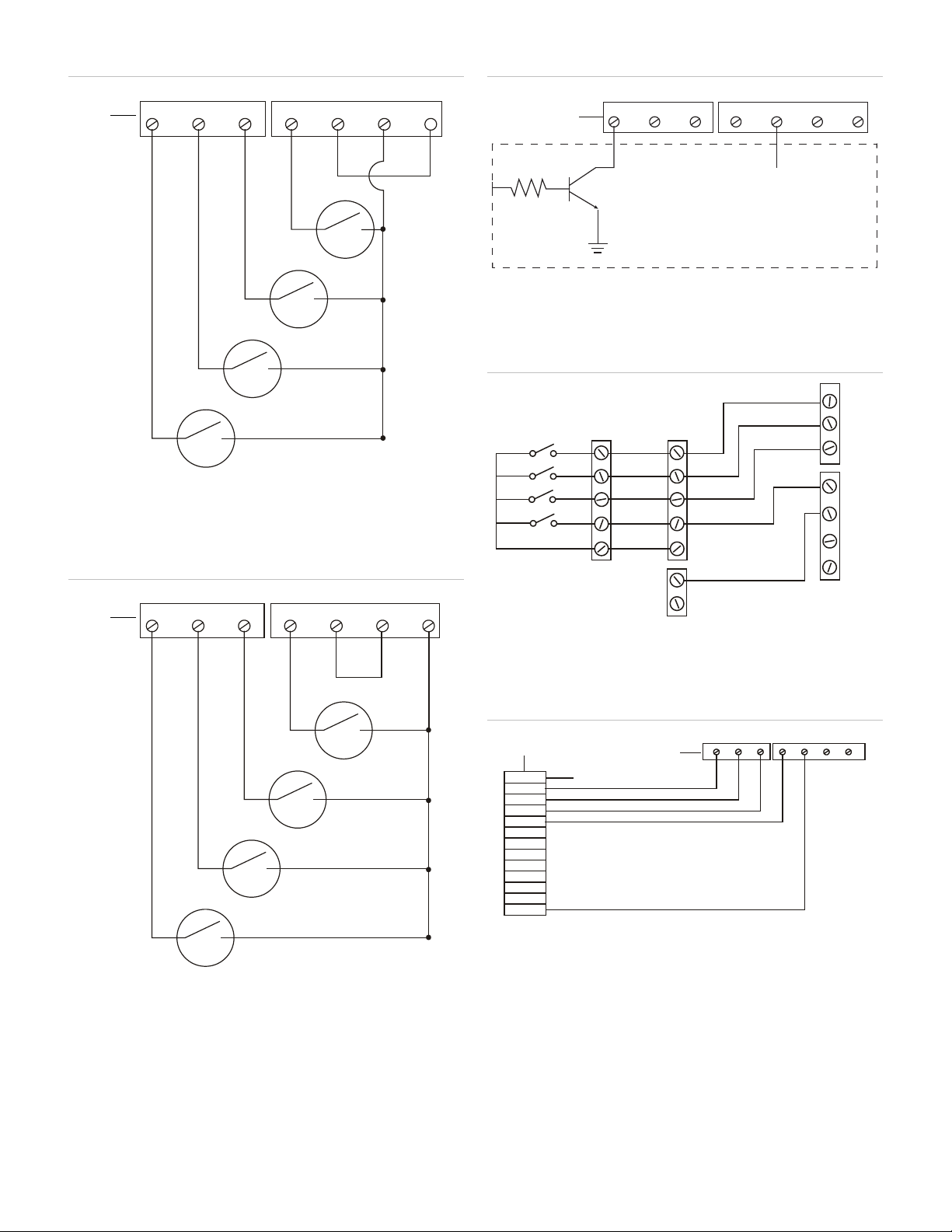
Figure 7: Installing with multiple dry relay contacts, 24 V input
(1) On input board
Note: Consult
versions of Adaptatone.
(1) On input board
(1) On input board
(2)
(3) Customer circuit
(1) 5531B-*
(2)
(3)
(4) Adaptatone Millennium connections 5531M-24*
(1) PLC
(2)
(3)
Note: See Table 5 for PLC compatibility requirements.
K4
K3
K2
K1
IN1 IN2
IN3
IN4 N
+VS
(1)
GND
K4
K3
K2
K1
IN1 IN2 IN3
IN4 N
+VS GND
(1)
IN4 N
+VS GNDIN3
IN2IN1
(1)
(2)
(3)
COM
GND
+VS
N
IN4
IN3
IN2
IN1
4
3
2
1
COM
4
3
2
1
(1)
(1)
(4)
(2)
(3)
VDC 1
OUT 0
OUT 1
OUT 2
OUT 3
OUT 1
OUT 2
OUT 3
OUT 4
OUT 5
OUT 6
IN1
IN2
IN3
IN4 N
+VS GND
OUT 7
DC COM
(1)
(2)
(3)
board (Method 1)
Figure 9: Installing with an open collector transistor, 24 V input
board
5 VDC to 24 VDC +/− 1% (from customer circuit)
Figure 10: Connecting to a “B” version Adaptatone, 24 V input
board (maximum 5 “M” versions)
Applications Engineering for compatibility with earlier
Figure 8: Installing with multiple dry relay contacts, 24 V input
board (Method 2)
4 / 8 P/N 3100008-EN • REV 06 • ISS 14JAN15
Bat (−) terminal 1
Bat (+) terminal 1
Figure 11: Connecting 24 V input board to a PLC
+24 VDC (external power source). Note: IN1 can be connected to
a 24 VDC priority signal for activation of external audio signal
connected to the Audio Input Board.
Input board
Page 5

Figure 12: Installing with multiple dry contacts, 120 V input board
(1) On input board
(2) Neutral
(3) 120 VAC
(4) Line
(1) PLC
(2) L1 120 VAC (AC Hot)
(3) On input board
(4) To PLC AC Com
Voltage
Current
Dimensions
Weight
Hazardous locations
Non
Model
5531M
5531M
5531M
5531MHV
5531MV
5531MV
5531M
5531M
5531MHV
5531MHV
5531MV
Model
Voltage
Current
5531M
5531M
5531M
5531MHV
5531MHV
5531MV
5531MV
5531M
5531M
5531MHV
5531MV
Model
553
24 VAC 50/60 Hz
0.10 A
1.3 A
553
5531MV
553
5531MV
5531M
5531MV
5531M
5531MHV
24 VAC 50/60 Hz
0.10 A
2.3 A
K4
K3
K2
K1
IN1 IN2 IN3
IN4 N
+VS GND
(3)
(4)
(1)
(2)
VAC 1
OUT 0
OUT 1
OUT 2
OUT 3
VAC 2
OUT 1
OUT 2
OUT 3
OUT 4
OUT 5
OUT 6
OUT 7
IN1
(1)
(2)
(3)
(4)
IN2
IN3
IN4 N
+VS GND
Specifications
Refer to Table 2 and Table 3
Refer to Table 2 and Table 3
Refer to Table 4
9 lb. (4.1 kg)
Ambient temp.
hazardous locations
Variable ambient temp. −40 to 151°F (−40 to +66°C)
Table 1: Hazardous locations
Supply
wire
-24AQ
75°C T3C (160°C, 320°F)
-24N5
-120N5
-24AQ
-24N5
-120N5
-24Y6
75°C T3C (160°C, 320°F)
-120Y6
-24Y6
-120Y6
-24Y6
−31 to 104°F (−35 to +40°C)
Class I, Div. 2
Groups A, B, C, D
T3C (160°C, 320°F)
T3C (160°C, 320°F)
T3A (180°C, 356°F)
T3C (160°C, 320°F)
T3C (160°C, 320°F)
T3C (160°C, 320°F)
T3A (180°C, 356°F)
T3A (180°C, 356°F)
T3C (160°C, 320°F)
Class II, Div. 2,
Groups F, G,
Class III, Div. 1, 2
T5 (100°C, 212°F)
T5 (100°C, 212°F)
Figure 13: Connection from a PLC to input board, 120 V input
board. See Table 5
Maintenance and testing
WARNING: To prevent fire, shock and component damage, no work
including circuit board removal, should be performed while the circuit is
energized.
Note: Any kind of service or maintenance performed while unit is
energized will void the warranty.
Examine the unit semi-annually for accumulation of dirt. Clean if
necessary.
The Adaptatone should be tested annually or as required by the
authority having jurisdiction to ensure continuous service.
P/N 3100008-EN • REV 06 • ISS 14JAN15 5 / 8
Table 2: Input board power
-24AQ
-24N5
-24Y6
-24AQ
-24Y6
-24N5
-24Y6
-120N5
-120Y6
-120Y6
-120N5
Table 3: Main power
Voltage Standby
1M-24AQ 24 VDC
1M-24N5
-24N5
1M-24Y6
-24Y6
-120N5
-120N5
-120Y6 125 VDC
-24AQ 24 VDC
24 VDC 6 mA
120V 50/60 Hz 13 mA
Tone on
current
0.10 A
current
0.74 A
120 VAC 50/60 Hz 0.10 A 0.36 A
125 VDC
250 VDC
120 VAC 50/60 Hz
240 VAC 50/60 Hz
0.10 A
0.02 A
0.10 A
0.10 A
0.21 A
0.10 A
0.32 A
0.20 A
120 VAC 50/60 Hz 0.10 A 0.38 A
250 VDC
120 VAC 50/60 Hz
240 VAC 50/60 Hz
0.10 A
0.02 A
0.10 A
0.10 A
0.10 A
0.20 A
0.10 A
0.31 A
0.20 A
1.5 A
Page 6

Model
Voltage Standby
5531MHV
240 VAC 50/60 Hz
0.10 A
0.34 A
5531MHV
240 VAC 50/60 Hz
0.10 A
0.37 A
A
B
C
Model
5531M-24AQ
24 VDC only
2 mA
740 mA
8 A / 4 mS
5531M
5531MV-24N5
5531M
5531MV-120N5
5531MHV-24AQ
24 VDC only
2 mA
1500 mA
8 A / 4 mS
Input board circuit
24 VDC
2 mA
6 mA
--
Input board circuit
120 VAC 50/60 Hz
5 mA
13 mA
--
Tone
Hex
No Tone
OFF
OFF
OFF
OFF
OFF
OFF
00
Ding
damped to 0
01
Warble
OFF
OFF
OFF
OFF
ON
OFF
575 and 770 Hz alternately, 87 ms each
02
Siren
OFF
OFF
OFF
OFF
ON
ON
600 to 1250 Hz up and down sweep in 8 s and repeat
03
Stutter
OFF
OFF
OFF
ON
OFF
OFF
Percussive 470 Hz, 83 ms on, 109 ms off
04
Slow Whoop
OFF
OFF
OFF
ON
OFF
ON
600 to 1250 Hz upward sweep in 4 s and repeat
05
Beep
OFF
OFF
OFF
ON
ON
OFF
470 Hz, 0.55 s on, 0.55 s off
06
Chime 1
OFF
OFF
OFF
ON
ON
ON
700 Hz percussive repeat at 1 Hz
07
Fast Whoop
OFF
OFF
ON
OFF
OFF
OFF
600 to 1250 Hz upward in 1 s and repeat
08
Hi/Lo
OFF
OFF
ON
OFF
OFF
ON
780 to 600 Hz alternately, 0.52 s each
09
Rapid Siren
repeat
0A
Yeow
OFF
OFF
ON
OFF
ON
ON
1250 to 600 Hz downward sweep in 1.6 s and repeat
0B
Horn
OFF
OFF
ON
ON
OFF
OFF
470 Hz continuous
0C
Air Horn
OFF
OFF
ON
ON
OFF
ON
370 Hz continuous
0D
Dual Tone
OFF
OFF
ON
ON
ON
OFF
470 to 500 Hz, 0.4 to 0.5 s cycle
0E
Chime 2
OFF
OFF
ON
ON
ON
ON
575 Hz percussive repeat at 1 Hz
0F
Westminster
OFF
ON
OFF
OFF
OFF
OFF
Two measures, 411 Hz, 520 Hz, 407 Hz, 312 Hz
10
Three Blind
333 Hz
11
Phasor
OFF
ON
OFF
OFF
ON
OFF
416 to 625 Hz up and down sweep in 13 ms and repeat
12
Telephone
delay and repeat
13 Staircase
repeat
14 3 Tone Alert
and repeat
15
RESERVED
OFF
ON
OFF
ON
ON
OFF
RESERVED
16
A
B
C
-24Y6 125 VDC
250 VDC
120 VAC 50/60 Hz
-120Y6 125 VDC
250 VDC
120 VAC 50/60 Hz
Table 5: PLC compatibility
Operating voltage Max. off state leakage
current
0.10 A
0.02 A
0.10 A
0.10 A
0.02 A
0.10 A
Tone on
current
0.39 A
0.19 A
0.56 A
0.40 A
0.20 A
0.62 A
current
Table 4: Dimensions
5531M 5531MHV
8 7/8 in. (225 mm) 11 1/2 in. (292 mm)
8 1/4 in. (210 mm) 9 3/4 in. (248 mm)
13 in. (330 mm) 14 1/4 in. (362 mm)
Continuous on current Surge (inrush/duration)
-24N5
-120N5
Note: PLC output must meet these product input parameters. Refer to Figure 11 and Figure 13.
Table 6: Tone programming
SW4-6 SW4-5 SW4-4 SW4-3 SW4-2 SW4-1 Description
-Dong OFF OFF OFF OFF OFF ON Percussive pairs of 700 and 570 Hz tones, each
OFF OFF ON OFF ON OFF 600 to 1250 Hz up and down sweep in 0.25 s and
120 VAC 50/60 Hz 2 mA 360 mA 2.82 A / 4 mS
120 VAC 50/60 Hz 5 mA 380 mA 2.82 A / 4 mS
Mice OFF ON OFF OFF OFF ON Four measures, 787 Hz, 714 Hz, 625 Hz, 952 Hz,
OFF ON OFF OFF ON ON 570 and 770 Hz alternately, 50 ms each for 1.2 s, 1.5 s
OFF ON OFF ON OFF OFF 440 to 2000 Hz up and down steps, 750 ms delay and
OFF ON OFF ON OFF ON 463 Hz, 641 Hz, and 896 Hz, 200 ms each, 1 s delay
6 / 8 P/N 3100008-EN • REV 06 • ISS 14JAN15
Page 7

Tone
SW4-6 SW4-5 SW4-4 SW4-3 SW4-2 SW4-1 Description
Hex
RESERVED
OFF
ON
OFF
ON
ON
ON
RESERVED
17
RESERVED
OFF
ON
ON
OFF
OFF
OFF
RESERVED
18
RESERVED
OFF
ON
ON
OFF
OFF
ON
RESERVED
19
RESERVED
OFF
ON
ON
OFF
ON
OFF
RESERVED
1A
NFPA Whoop
delay and repeat
1B 3 Pulse Horn
1.5 s delay and repeat
1C 3 Pulse Air Horn
[1]
1.5 s delay and repeat
1D
3 Pulse Dual Tone
[1]
separated by 0.5 s followed by 1.5 s delay and repeat
1E
3 Pulse Chime 2
[1]
1.5 s delay and repeat
1F
European Police
ON
OFF
OFF
OFF
OFF
OFF
969 Hz and 800 Hz alternately 0.250 s each
20
European Fire
ON
OFF
OFF
OFF
OFF
ON
982 Hz and 864 Hz downward sweep in 0.134 s
21
European Slow
Whoop
delay and repeat
22
European General
ON
OFF
OFF
OFF
ON
ON
1087 Hz for 0.5 s followed by 0.5 s delay and repeat
23
European Toxic
ON
OFF
OFF
ON
OFF
OFF
982 Hz continuous
24
European Police 2
ON
OFF
OFF
ON
OFF
ON
554 Hz and 440 Hz alternately, 0.8 s each
25
European Stutter
repeat
26 European Sweep
repeat
27
Telephone 2
ON
OFF
ON
OFF
OFF
OFF
Alternate tones at 567 Hz and 326 Hz
28
Buzzer
ON
OFF
ON
OFF
OFF
ON
1315 Hz and 746 Hz alternating for 0.003 s each
29
Genesis Horn Cont
ON
OFF
ON
OFF
ON
OFF
Continuous Genesis horn
2A
Genesis Horn
Temp
2B
Warning 1
ON
OFF
ON
ON
OFF
OFF
1207 Hz and 493 Hz, alternately 0.002 s each
2C
Warning 2
ON
OFF
ON
ON
OFF
ON
2336 Hz and 493 Hz, alternately 0.005 s each
2D
Warning 2 Beep
0.005 s followed by 1 s delay
2E
Caution
0.050 s
2F
Multi
alternately on for 0.050 s
30
Attention
alternately on for 0.003 s
31 High Freq. Steady
Alert
32
High Freq. Fast
Siren
33 High Freq. Slow
Siren
34 DIN PFEER
repeat
35
NF S 32 001
ON
ON
OFF
ON
ON
OFF
584 Hz for 0.100 s and 461 Hz for 0.400 s
36
Ode to Joy
ON
ON
OFF
ON
ON
ON
6.45 s of melody followed by 1 s delay and repeat
37
Twinkle Little Star
ON
ON
ON
OFF
OFF
OFF
13.2 s of melody followed by 1 s delay and repeat
38
Dueling Banjos
ON
ON
ON
OFF
OFF
ON
10.84 s of melody followed by 1 s delay and repeat
39
La Cucaracha
ON
ON
ON
OFF
ON
OFF
7.10 s of melody followed by 1 s delay and repeat
3A
Yellow Rose of TX
ON
ON
ON
OFF
ON
ON
19.34 s of melody followed by 1 s delay and repeat
3B
[1] 3 Pulse tones are for evacuation use only.
OFF ON ON OFF ON ON Three 422 to 775 Hz upward sweeps, 850 ms each, 1 s
[1] OFF ON ON ON OFF OFF 470 Hz, 3 0.5 s pulses separated by 0.5 s followed by
OFF ON ON ON OFF ON 370 Hz, 3 0.5 s pulses separated by 0.5 s followed by
OFF ON ON ON ON OFF 450 to 500 Hz, 0.4 to 0.5 s cycle, 3 0.5s pulses
OFF ON ON ON ON ON 575 Hz, 3 0.5 s pulses separated by 0.5 s followed by
ON OFF OFF OFF ON OFF 658 to 1312 Hz upward sweep in 3 s followed by 0.5 s
ON OFF OFF ON ON OFF 3876 Hz for 0.146 s followed by 0.102 s delay and
ON OFF OFF ON ON ON 1315 Hz to 413 Hz downward sweep in 1.17 s and
ON OFF ON OFF ON ON Temporal Genesis horn
ON OFF ON ON ON OFF 0.500 s of 2336 Hz and 493 Hz each alternating for
ON OFF ON ON ON ON 453 Hz for 0.040 s, 235 Hz for 0.020 s, 235 Hz for 0.160
s, 260 Hz for 0.050 s, 260 Hz for 0.1009 s, 235 Hz for
-tone ON ON OFF OFF OFF OFF 376, 357, 352, 382, 355, 375, 384, 375 and 364 Hz
ON ON OFF OFF OFF ON 2232, 4545, 3704, 2777, 4347, 3704, 2500 Hz
ON ON OFF OFF ON OFF 2500 Hz continuous
ON ON OFF OFF ON ON 2500 to 3048 Hz up and down sweep in 0.130 s
ON ON OFF ON OFF OFF 2500 to 3048 Hz up and down sweep in 0.500 s
ON ON OFF ON OFF ON Ramp downward from 1336 Hz to 522 Hz in 1.2 s and
Note: The use of evacuation signals on this product, which is not
specifically listed for fire alarm use, is subject to the approval of the
authority having jurisdiction.
P/N 3100008-EN • REV 06 • ISS 14JAN15 7 / 8
Page 8

Regulatory information
Ratings
ANSI/ISA 12.12.01
CAN/CSA C22.2 No. 14
CAN/CSA C22.2 No. 157
CAN/CSA C22.2 No. 205
CAN/CSA C22.2 No. 213
NEMA Type 3R
UL 464
Contact information
For contact information, see www.edwardssignaling.com.
© 2015 UTC Fire & Security Americas Corporation, Inc.
All rights reserved.
8 / 8 P/N 3100008-EN • REV 06 • ISS 14JAN15
 Loading...