

Page 1
Technical Bulletin No.: 970524
Date: 2/4/00
Product: Chameleon
Product Category: AdaptaBeacons
Subject: PLC Connectivity of 103 Chameleon
The Chameleon 103I Series features an on-board processor with an internal
jumper, which allows the single unit to function as either a steady or flashing visual
signal. Either a PLC or contact closure can activate any one or all three lights.
The first light activated will illuminate either steady or flashing (determined by the
internal jumper position). When a second light is activated, the Chameleon cycles
between the two colors and activation of a third light causes it to cycle between all
three colors.
The 103 model performs similar to the 103I, but all signal operation in the
103 is controlled directly through a PLC’s ladder logic, rather than through the
Chameleon’s internal processor. The PLC will control which color LED’s are on,
how long they are on and whether they are steady-on or flashing.
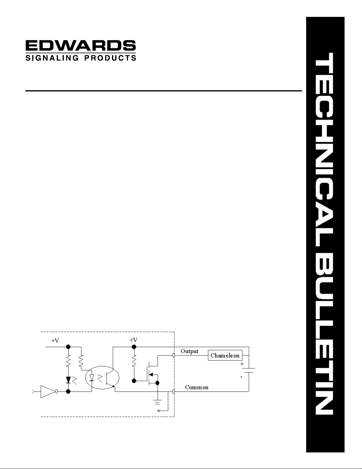
For PLC connectivity, there are two considerations that need to be
addressed for proper operation of the Chameleon Multi-status Indicator. The first
consideration has to do with the type of output card utilized on your PLC. Both the
103 and the 103I require the PLC to have a Sinking Output card. For the
Chameleon to operate properly you must have a Sinking Output. The illustration
below shows a Sinking Output.
NOTE: It is important to make sure the Output Card on your PLC has a
Sinking Output.
Technical Bulletin # 970524 Page 1 of 4
Page 2

The second consideration has to with 120VAC units. A resistor has to be
added to the circuit to eliminate any leakage current that can false activate the
Chameleon. The following calculation will guide you in determining the proper size
resistor to use with your specific PLC.
Step 1:
I
LPLC
– I
MLChameleon
+ 2 mA = I
Dissipated
Where;
I
= Leakage Current from your PLC
LPLC
I
MLChameleon
= Maximum Allowable
Leakage Current for the
Chameleon
2 mA = Tolerance Factor
I
Dissipated
= The amount of current to be
dissipated
Step 2:
V
Output
/ I
Dissipated
= R
Where;
V
= 120VAC Output from your PLC
Output
I
Dissipated
= The amount of current to be
dissipated
Step 3:
P = I
Dissipated
* V
Output
Where;
P = Wattage rating for your dissipating
resistor
= 120VAC Output from your PLC
V
Output
I
Dissipated
= The amount of current to be
dissipated
R = Resistor value to dissipate leakage
current
Example:
Your 120 VAC PLC output card has a leakage current of 15 mA. What size resistor will you
need to use to dissipate the leakage current?
Step 1:
I
LPLC
– I
MLChameleon
+ 2 mA = I
Dissipated
15 mA – 5 mA + 2 mA = 12 mA
Step 2:
V
Output
/ I
Dissipated
= R
120VAC / 12 mA = R
R = 10,000 ohms
Technical Bulletin # 970524 Page 2 of 4
Step 3:
P = I
Dissipated
* V
Output
P = 12 mA * 120 VAC
P = 1.44 watts
Therefore, your resistor needs to be
10,000 ohms and 1.5 watts.
Page 3

PLC Electrical Characteristics
As with any product being connected to the output card of a PLC, there are
certain electrical characteristics that must be taken into consideration.
1. Operating Voltage - the voltage that must be applied to the unit for it to
function properly.
• Criteria - The operating voltage must be within the range of the PLC
output card.
• What if the signal is rated higher than the PLC output card? - The
signal will not function properly.
• What if the signal is rated lower than the PLC output card? – The
signal could be damaged by over voltage and the PLC card could also
be damaged.
2. Surge (inrush/duration) - The instantaneous current surge that occurs each
time the signal is turned on. It is defined as a current over a period of time.
• Criteria - Both current magnitude and time duration of the surge inrush,
for the signal, must be within the range specified for the PLC output
card.
• What if the signal surge current falls within the range, but the time
duration for the surge is beyond the range compared to the PLC output
card and vice versa? - The user should consult with the PLC
manufacturer for additional data. Failure to do so could damage the
output card.
3. Continuous-on Current - The current that the signal will draw in continuous
operation.
• Criteria - For Triac outputs there are two criteria to consider, the
minimum load required by the output card to keep it turned on and the
continuous-on current that the card can safely supply. The continuouson current for the signal must fall between the minimum load current
and the continuous- on current of the PLC, for the signal to function.
• What if the signal’s continuous-on current is below the minimum load
current for the PLC? - The signal will not function because the PLC will
not turn on.
• What if the signal’s continuous-on current is above the continuous on
current rating for the PLC? - The PLC output card could be damaged
due to excessive current draw.
Technical Bulletin # 970524 Page 3 of 4
Page 4

4. Off State Leakage Current - The current that leaks from the PLC in it’s off
g
(
)
g
(
)
state.
• Criteria - The off state leakage current from the PLC must be less than
the maximum allowable off state leakage current for the signal.
• What if the off state leakage current from the PLC is greater than the
maximum allowable off state leakage current for the signal? - The
signal may turn on and false activate.
Electrical Characteristics for the 103 Series Chameleon
Operating
Volta
Cat. No. Volts mA mA A/mSeconds**
103-RBA-G1 24V DC 5 65 0.070/8
103-RGA-G1
103-RBA-N5 120V AC 5 55 0.100/8
103-RGA-N5
* All AC volts at 60 Hz ** Amps/milliseconds
e
Max. off state
leakage current
Continuous
on current
Surge
Inrush/duration
Electrical Characteristics for the 103I Series Chameleon
Operating
Volta
Cat. No. Volts mA mA A/mSeconds**
103I-RBA-G1 24V DC 5 55 0.070/8
103I-RGA-G1
103I-RBA-N5 120V AC 5 45 0.100/8
103I-RGA-N5
* All AC volts at 60 Hz ** Amps/milliseconds
e
Max. off state
leakage current
Continuous
on current
Surge
Inrush/duration
Technical Bulletin # 970524 Page 4 of 4
 Loading...