

Page 1
Installation Instructions for Catalog Series 5560M
Mini-Mi
TM
Signal
Installation
Installation should be completed in accordance with either the National Electrical Code or the Canadian Electrical Code, applicable
local codes.
1. Remove (4) screws from cover and remove cover. Mount
backplate on a 4" (102 mm) electrical box using (2) #8-32 x 5/8"
screws (provided) and (2) #8 steel washers (provided) or other
suitable hardware. For weatherproof applications, mount to
the Cat. No. 449 back box (purchased separately) using (4) #632 x 3/4" screws (provided) and (4) #8 steel washers (provided)
or other suitable hardware.
Description and Operation
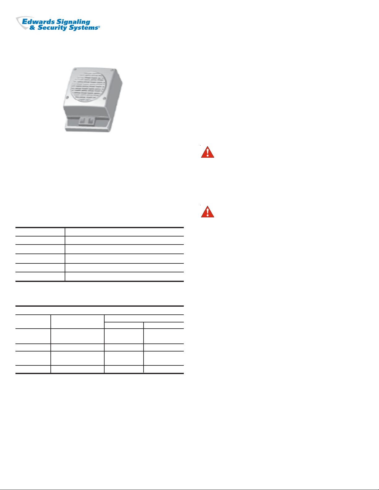
Edwards Catalog Series 5560M is an integrated communication
system designed to sound 55 system tones or one 20-second voice
message in factory, hallway, office and personnel areas. The MiniMi is available either with or without a strobe. The Mini-Mi has
three modes of operation: stand-alone tone generation, stand-alone
voice generation and system audio operation. The Mini-Mi is in a
NEMA Type 3R enclosure and is UL and cUL Listed.
Five modules are available for use with the Mini-Mi.
Catalog Number Description
556A-M Audio Coupler Module
556A-M485 Audio Coupler Module with RS485 Connectivity
556T-M Tone Module
556T-M485 Tone Module Board with RS485 Connectivity
556V-M Voice Module
Electrical Specifications
INPUT POWER
Catalog Typical Current (A)
Number Voltage Standby Tone On
5560M-AQ 24V DC .03 .070
24V AC 50/60 Hz .08 .16
5560M-N5 120V AC 50/60 Hz .03 .088
5560MS-AQ 24V DC .03 .070
24V AC 50/60 Hz .08 .16
5560MS-N5 120V AC 50/60 Hz .03 .086
CAUTION: To prevent damage to the circuit and to otherwise assure
continued proper functioning, DO NOT operate the unit outside of the
Regulated 24V DC/FWR voltage range of 16 - 33V DC/V FWR.
CAUTION
During installation, take care not to damage
components on the printed circuit board.
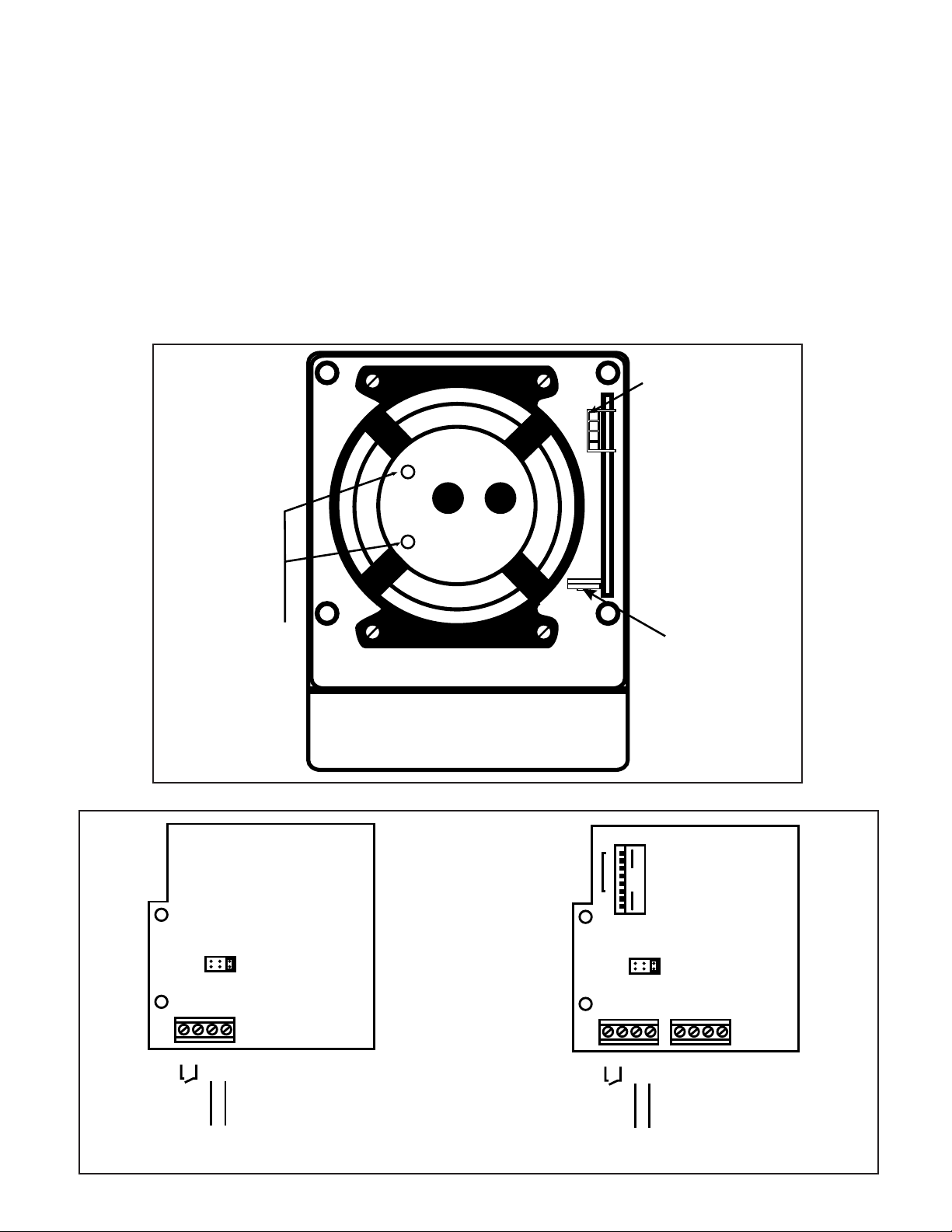
2. Remove (2) screws holding pc board to speaker in the Mini-Mi
housing and remove pc board. (See Figure 1.)
WARNING
Do not apply power to the unit until installation is
completed and housing cover and outlet box cover are
secured.
3. Insert appropriate module, plugging it into the main board.
Secure to speaker using screws removed in step 2. (Figure1)
4. Connect green ground wire to earth ground.
Feed power source wires through the backplate and connect
to the unit's power source leads. Observe polarity for DC units.
For models with strobes, connect a second set of power source
wires to the strobe power leads.
5. Select the appropriate module from below and make
connections and settings as described below.
Audio Coupler Module Boards
Connect incoming 10V, 25V or 70V RMS audio line to AUD (+)
and AUD (-) as shown in Figure 2.
Place the audio voltage jumper on the appropriate audio voltage
(Figure 2).
Tone Module Boards
Set miniature programming switch on the printed circuit board
(Figure 3) for the desired tone. Refer to Table 2.
RS485 Activation
For models with RS485 activation, connect the RS485 wires to
terminals + TX/RX and - TX/RX on the module.
Set the dipswitch on the PC board for the appropriate baud rate
(Table 1) and address (Table 2) as shown in Figures 2 and 3.
Cheshire, CT 06410 203-699-3300 (Ph)
P/N 3100792 ISSUE 1A © 2005
203-699-3365 (Cust. Serv. Fax)
203-699-3078 (Tech. Serv. Fax)
Page 2
Set 100-ohm termination jumper (if required) JPx on PC board.
Network termination is required if the unit is located at the
beginning or end of the network bus. Termination reduces
unwanted reflections caused by signal propagation.
Voice Module
One twenty-second message can be recorded on the voice
module.
Apply power to unit. press and hold the record button while
speaking clearly into the microphone to record your message.
Release the button when recording is complete. Refer to Figure
4.
6. Place housing on backplate and secure using (4) screws
removed in step 1.
7. Adjust volume using the potentiometer on the main board
(Figure 1).
8. Verify operability.
Maintenance and Test
Examine the unit semi-annually for external accumulation of dirt.
Clean if necessary.
To test the message, press RUN. To stop message play, remove
power from the unit.
Adjust volume for voice output using the potentiometer on the
voice module board (Figure 4).
Mounting Holes
to Secure
Module to Speaker
The Adaptatone should be tested annually or as required by the
local authority having jurisdiction to ensure continuous service.
Connector - Plug
Appropriate Module into
Main Board
Potentiometer
to Adjust
Main Volume
P/N 3100792 ISSUE 1
AUDIO VOLTAGE
AB
ELECTRICAL
SUPERVISION
AUDIO IN
(10V, 25V, or 70V RMS)
70V
AUD(-)
25V
AUD(+)
Figure 1. Mini-Mi Housing
12345678
ADDRESS BAUD
OPEN
10V
AUDIO VOLTAGE
AB
ELECTRICAL
SUPERVISION
AUDIO IN
(10V, 25V, or 70V RMS)
70V
AUD(-)
25V
AUD(+)
10V
-TX/RX +TX/RX
556A-M485 (with RS485 Connectivity)556A-M
Figure 2. Audio Coupler Modules
PAGE 2
Page 3

Dipswitch for Tone Selection
(Refer to Table 2)
12345678
OPEN
556T-M485 (with RS485 Connectivity)556T-M
Figure 3. Tone Generator Module
POTENTIOMETER
12345678
ADDRESS BAUD
OPEN
-TX/RX +TX/RX
RUN RECORD
MICROPHONE
Figure 4. Voice Module
Table 1. Network Baud Rate setting
Baud Rate 7 8
1200 OPEN OPEN
2400 CLOSED OPEN
9600 OPEN CLOSED
19200 CLOSED CLOSED
PAGE 3
P/N 3100792 ISSUE 1
Page 4

Table 2. Tone Programming and Switch Configuration
SWITCH POSITIONS 1 2 3 4 5 6 DESCRIPTION HEX
Ding Dong 01
Warble
Siren
Stutter
Slow Whoop
Beep
Chime 1
Fast Whoop
Hi/Lo
Rapid Siren
Yeo w
Horn
Air Horn
Dual Tone
Chime 2
Westminster
Three Blind Mice
Phasor
Telephone
Staircase
3 Tone Alert
RESERVED
RESERVED
RESERVED
RESERVED
RESERVED
NFPA Whoop
3 Pulse Horn*
3 Pulse Air Horn*
3 Pulse Dual Tone*
3 Pulse Chime 2*
European Police
European Fire
European Slow Whoop
European General
European Toxic
European Police 2
European Stutter
European Sweep
Telephone 2
Buzzer
Genesis Horn Cont.
Genesis Horn Temp.
Warning 1
Warning 2
Warning 2 Beep
Caution
Multi-tone
Attention
High Freq. Steady Alert
High Freq. Fast Siren
High Freq. Slow Siren
DIN PFEER
NFS 32 001
Ode to Joy
Twinkle Little Star
Dueling Banjos
La Cucaracha
Yellow Rose of Texas
*3 Pulse Tones are for Evacuation Use Only.
P/N 3100792 ISSUE 1
Percussive pairs of 700 and 570 Hz tones each damped to zero
575 and 770 Hz alternately, 87 ms each
600-1250 Hz up and down sweep in 8 seconds and repeat
Percussive 470 Hz, 83 ms on, 109 ms off
600-1250 Hz upward sweep in 4 seconds and repeat
470 Hz, 0.55 seconds on, 0.55 seconds off
700 Hz percussive repeat at 1 Hz
600-1250 Hz upward sweep in 1 second and repeat
780 to 600 Hz alternately, 0.52 seconds each
600-1250 Hz up and down sweep in 0.25 seconds and repeat
1250 - 600 Hz downward sweep in 1.6 seconds and repeat
470 Hz continuous
370 Hz continuous
450 - 500 Hz, 0.4 to 0.5 second cycle
575 Hz percussive repeat at 1 Hz
Two measures: 411 Hz, 520 Hz, 407 Hz, 312 Hz
Four measures: 787 Hz, 714 Hz, 625 Hz, 952 Hz, 333 Hz
416 - 625 Hz up and down sweep in 13 ms and repeat
570 and 770 Hz alternately, 50 ms each for 1.2s, 1.5 s delay and repeat
440 - 2000 Hz up and down steps, 750 ms delay and repeat
463, 641 and 896 Hz, 200 ms each 1 second delay and repeat
RESERVED
RESERVED
RESERVED
RESERVED
RESERVED
Three 422 - 775 Hz upward sweeps, 850 ms each, 1s delay and repeat
470 Hz, 3 0.5s pulses separated by 0.5s followed by 1.5s delay and repeat
370 Hz, 3 0.5s pulses separated by 0.5s followed by 1.5s delay and repeat
450 - 500 Hz, 0.4 to 0.5s cycle, 3 0.5s pulses separated by 0.5s followed by
1.5s delay and repeat
575 Hz, 3 0.5s pulses separated by 0.5s followed by 1.5s delay and repeat
969 Hz and 800 Hz alternately 0.250 seconds each
982 Hz and 864 Hz downward sweep in 0.134 seconds
658 Hz to 1312 Hz upward sweep in 3s followed by 0.5s delay and repeat
1087 Hz for 0.5 seconds followed by 0.5 second delay and repeat
982 Hz continuous
554 Hz and 440 Hz alternately 0.800 seconds each
3876 Hz for 0.146 seconds followed by 0.102 seconds delay and repeat
1315 Hz to 413 Hz downward sweep in 1.17 seconds and repeat
Alternate tones at 567 Hz and 326 Hz, for 0.052 seconds each
1315 Hz to 746 Hz alternating for 0.003 seconds each
Continuous Genesis horn
Temporal Genesis horn
1207 Hz and 493 Hz, alternately 0.002 seconds each
2336 Hz and 493 Hz, alternately 0.005 seconds each
0.500s of 2336 Hz and 493 Hz each alternating for 0.005s followed by 1s delay
453 Hz for 0.040s, 235 Hz for 0.020s, 235 Hz for 0.160s, 260 Hz for 0.050s,
260 Hz for 0.1009s, 235 Hz for 0.050s
376, 357, 352, 382, 355, 375, 384, 375 and 364 Hz alternately on for 0.050s
2232, 4545, 3704, 2777, 4347, 3704, 2500 Hz alternately on for 0.003s
2500 Hz continuous
2500 to 3048 Hz up and down sweep in 0.130 seconds
2500 to 3048 Hz up and down sweep in 0.500 seconds
Ramp downward from 1336 Hz to 522 Hz in 1.2 seconds and repeat
584 Hz for 0.100 seconds and 461 Hz for 0.400 seconds
6.45 seconds of melody followed by 1 second delay and repeat
13.2 seconds of melody followed by 1 second delay and repeat
10.84 seconds of melody followed by 1 second delay and repeat
7.10 seconds of melody followed by 1 second delay and repeat
19.34 seconds of melody followed by 1 second delay and repeat
SWITCH POSITIONS 7 & 8 UNUSED
Closed / On Switch =
Open / Off Switch =
1 2 3 4 5 6 7 8
02
03
04
05
06
07
08
09
0A
0B
0C
0D
0E
0F
10
11
12
13
14
15
16
17
18
19
1A
1B
1C
1D
1E
1F
20
21
22
23
24
25
26
27
28
29
2A
2B
2C
2D
2E
2F
30
31
32
33
34
35
36
37
38
39
3A
3B
PAGE 4
 Loading...