

Page 1
PLAINVILLE, CT 06062
41 WOODFORD AVE.
EDWARDS SIGNALING
TECHNICAL WRITING
RETURN MECHANICAL TO:
TO ACTUAL SIZE.
NOTE: MECHANICALS HAVE ALREADY BEEN REDUCED
CHARACTERS: TO BE BLACK ON WHITE BACKGROUND
MATERIAL: STANDARD WHITE OFFSET STOCK
WITH PART NUMBER ON THE OUTSIDE.
(1) 11" X 17" SHEET PRINTED BOTH SIDES. FOLD IN HALF
5553 SERIES ADAPTATONE SPEAKER
INSTALLATION INSTRUCTIONS FOR CATALOG SERIES
P/N 3101297 OFFSET SPEC
ECN: 13-C2085
FILE: 3101297
ISSUE: 2
APPROVED: GM
FOLD DETAIL REFERENCE ONLY
P/N 3101297
Page 2
5553 Series Adaptatone Millennium Speaker
P/N 3101297• REV 02 • REB 20FEB13
installation and
operation
Page 3

PAGE
2
Description and Operation
8 7/8"
(225 mm)
8 1/4"
(210 mm)
13"
(330 mm)
2.0" (51mm)
7.5"
(191mm)
1. Mount Adaptatone as shown in Figure 2.
Edwards 5553 series Adaptatone Speakers are UL Listed Audible
Signaling Appliances that are designed to accept system audio input
levels of 25 or 70 volts RMS. They are designed to be used in conjunction
with compatible control equipment for high intelligibility reproduction
of audible emergency and protecive signals as well as voice messages.
They comply with the requirements of UL Standard 1480, Fire Protective
Signaling Speakers. The speakers are suitable for outdoor use with a
UL1480 wet locations rated enclosure.
The speakers include a supervisory capacitor and are suitable for
installation in systems employing supervised circuitry (25V/70.7V).
Maximum supervised circuit voltage is 24VDC.
Speaker direction and the output level are easily adjustable. Output
wattage is easily adjusted by an internal rotary switch.
Additionally, the Adaptatone series are UL Listed as Audible Signal
Appliances for use in the following hazardous locations.
Catalog
Number
5553-25/70-G
5553-25/70-R
Class I, Div. 2, Groups A, B, C, D T4 (135)
Hazardous
Locations
Class II, Div. 2, Groups F, G
Class III, Div. 1 and 2
Temp.
Code
T5 (100C)
NOTE: C
2. Install wires through a knockout hole in the bottom of the box
a. Flat Surface Mounting. Secure unit to mounting surface
using the (4) mounting holes in the mounting plate on the
rear of the box. Use #10 x 3" (76 mm) wood screws (furnished
loose) or other hardware (not supplied) suitable for the
mounting surface.
b. Rigid Pipe Mounting. Loosen the (4) cover screws from the
signal box and lift off signal box cover.
over screws are captive. Do not remove from cover.
Remove the center knockout in lower wall of box and
mount box to a 1/2" (12.7 mm) conduit pipe using suitable
connector.
from a raceway that is, with its connections to the 1/2" (12.7 mm)
conduit knockout hole, approved for the same degree of protection
and enclosure type needed by the application.
WARNING
To prevent fire and shock, wire the Adaptatone only as described
in this installation instruction.
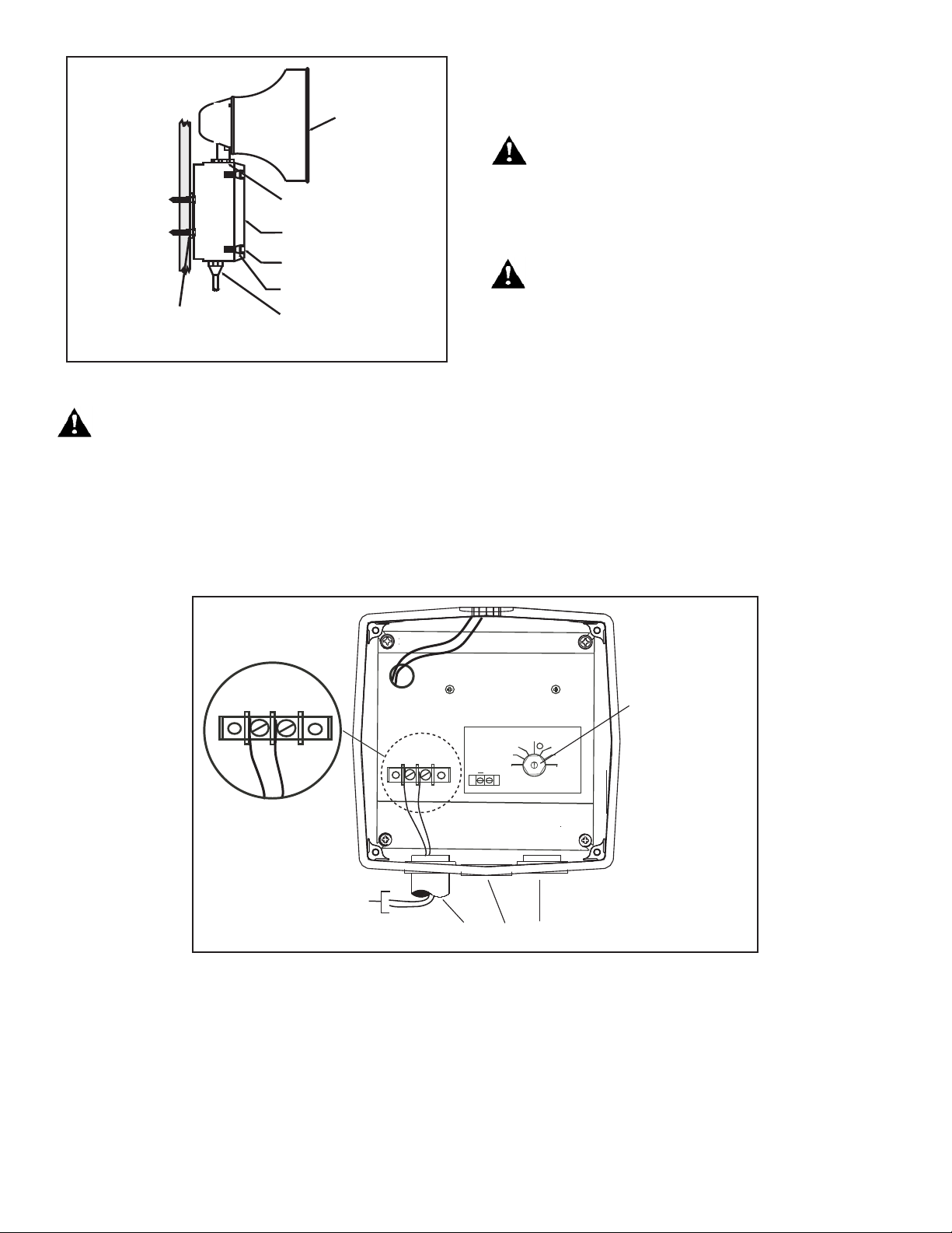
3. Wire as follows referring to Figure 3:
a. Connect audio in (+) and audio in (-) to the "AUDIO INPUT/
OUTPUT CONNECTIONS", 2-place terminal on faceplate.
Obser ve polarity on faceplate lab el. Sh ielded cabl e
recommended.
Side
Back
Figure 1. Speaker/Amplifier Dimensions
Specifications
Weight - Speaker/Amplifier .................................. 9 Pounds (4.1 kg)
Hazardous.Locations,.UL.Standard.UL1604
Ambient Temp. .................................................... -40F to +104F (-40C to +40C)
Non-Hazardous.Locations
Variable Ambient Temp. ..................................... -40F to +151F (-40C to +66C)
Frequency Range.............................................400Hz to 4,000Hz
Hazardous Locations and Variable Ambient Conditions apply only where UL
listings ar e accepted.
Installation
The Adaptatone Speaker may be mounted to any .at surface or may
be used as a freestanding unit mounted to a rigid pipe. The Adaptatone
must be installed in accordance with the latest edition of the National
Electrical Code or other regulations applicable to the country and locality of installation and by a trained and qualified electrician.
b. When connecting multiple speakers or supervised circuits;
Connect wires leading to next signal or end-of-line resistor
on the same INPUT/OUTPUT terminals (+) and (-) on the 2place terminal as shown in Figure 4. Again, polarity must be
observed.
4. Adjust voltage/wattage level by turning rotary switch located
on internal faceplate (Figures 3 & 4). See Table 1 for Power Tap
Selection Settings.
WARNING
To ensure integrity of the enclosure: Ensure the cover gasket,
part number P-007549-0069, is adhered into groove at cover
perimeter before replacing the signal box cover.
WARNING
Ensure that the (4) collar gaskets, part number P-041930-0362,
are in place on each cover screw before securing the signal
box cover.
When securing cover, start screws by hand, making sure
they are threaded into tapped holes in housing bosses before
securing with a screwdriver. Torque signal box cover screws to
a minimum of 20 in-lbs. This ensures the required tight fit.
5. Tightly secure the signal box cover using (4) retained cover
screws.
6. Torque signal box cover screws to a minimum of 20 in-lbs.
P/N 3101297 ISSUE 02
Page 4
Speaker
Large star nut to
adjust speaker
direction
Signal Box
(4) Cover
screws
(4) Collar
gaskets
Raceway and connections
(not supplied) to
1/2" (12.7 mm) knockout
hole
(4) #10 x 3" (76 mm)
screws or other hardware
suitable for the mounting surface
Figure 2. Adaptatone Mounting
15W 25V *
.9W70V
1.8W70V
0.48W25V
7.5W70V
15W7 0V
7.5W25V *
1.8W25V
0.94W25V
3.8W70V
* DO NOTUSE
FOR 70V
+
AUDIO INPUT CONNECTIONS
From Amplifier
+
_
1/2" Conduit Entries
Power Tap
Selection Switch
(See table 1)
+
_
WARNING
To ensure integrity of the Adaptatone assembly when
adjusting the speaker direction, make sure threads in the
enclosure remain fully engaged and do not turn speaker more
than 360 degrees from the original factory installed position.
8. Regardless of speaker direction adjustment, it is important that the
star nut be tightened wrench tight to ensure the speaker position
is maintained securely.
WARNING
High volume may cause harm to personnel in close proximity.
9. Verify operability.
Maintenance and Test
WARNING
Ensure that power is disconnected before cleaning inside of
unit.
Examine the unit semi-annually for accumulation of dirt. Clean if
necessary.
The Adaptatone should be tested annually or as required by the authority having jurisdiction to ensure continuous service.
7. To adjust speaker direction, loosen large star nut (Figure 3) and
turn speaker to the approximate desired position.
Figure 3. Wiring a Single 5553 Series Speaker (non supervised)
P/N 3101297 ISSUE 02
PAGE 3
Page 5

1/2" Conduit Entries
U.S.
T 800-336-4206
F 800-454-2363
Canada
T 519 376 2430
F 519 376 7258
Asia
T 852 2907 8108
F 852 2142 5063
Australia
T 61 3 9259 4700
F 61 3 9259 4799
Europe
T 32 2 725 11 20
F 32 2 721 86 13
Latin America
T 305 593 4301
F 305 593 4300
www.edwardssignaling.com
Table 1. Power Tap Selector Switch
Switch
Position Impedance
1 5.0K - - .9W 93
2 2.5K - - 1.8W 96
3 1.3K .48W 91 3.8W 98
4 666 .94W 93 7.5W 101
5 333 1.8W 96 15.0W 103
6 89 7.5W 101 Do Not Use
7 45 15.0W 103
25V
Line
SPL dB(A)
@ 10 ft.
70V
Line
SPL dB(A)
@ 10 ft.
on 70V
CAUTION
To ensure proper supervision of connection, do not use looped
wires under terminal screws. Break wire run. Use both sides
of terminal screws as shown.
Note: To conform with UL requirements, wires must be connected as shown in wiring diagram.
Wire size; 18 Gauge minimum, 12 Gauge maximum.
_
+
From Supervised
or Non Supervised
Amplifer
0.94W25V
7.5W70V
0.48W25V
3.8W70V
_
+
1.8W70V
.9W70V
+
AUDIO INPUT CONNECTIONS
1.8W25V
15W7 0V
7.5W25V *
15W 25V *
* DO NOT USE
FOR 70V
Power Tap
Selection Switch
(See table 1)
To Next Speaker or
End-of-Line Resistor
Figure 4. Wiring Multiple 5553 Seres Speakers and/or supervised circuits
PAGE 4 P/N 3101297 ISSUE 02
 Loading...