

Page 1
Description and Operation
Installation Instructions for Hazardous Location Use Adaptatone
Signal Catalog Number 5533MD-AW
Installation
Installation should be completed in accordance with either the
National Electrical Code or the Canadian Electrical Code, applicable local codes and the latest edition of either NFPA72, National
Fire Alarm Code, or CAN/ULC S524, Standard for the Installation of
Fire Alarm Systems.
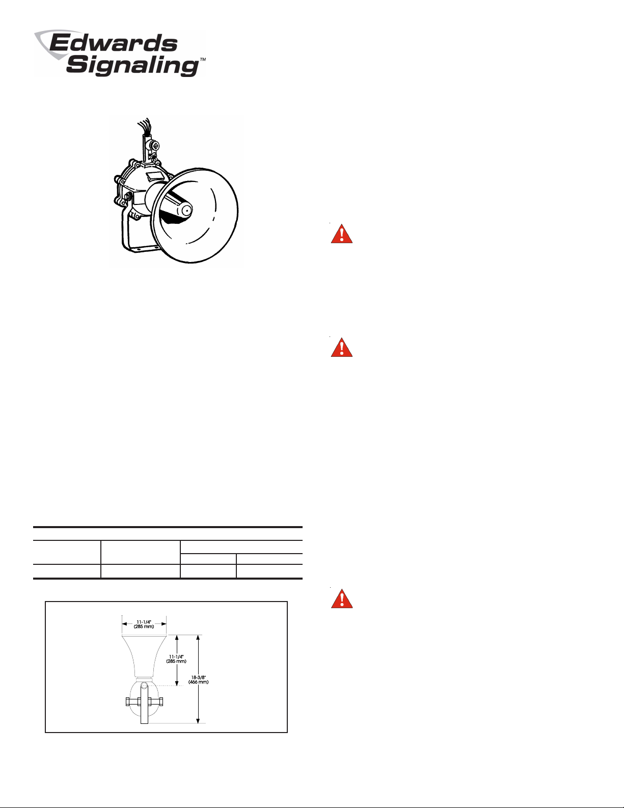
1. Mount Adaptatone to any solid surface using its mounting
bracket and (3) bolts (not supplied) (Figure 1).
WARNING
Keep mating surfaces of housing clean and
undamaged to maintain the integrity of the
Hazardous Location construction.
Edwards Hazardous Location Use Adaptatone signals, catalog
numbers 5533MD-AW, are tone-selectable, diode-polarized, audible signaling appliances primarily intended for use in fire alarm
systems and other applications requiring electrical supervision of
signaling circuit field wiring. The signals can be field programmed
to sound any of 56 tones. Descriptions of the tones are provided
in Table 1. Directions for tone programming and information regarding suitability of the tones for fire alarm use are provided on
the inside of the signal's housing cover.
The 5533MD-AW models are UL and ULC listed for safe use in
Class I Groups B, C and D atmospheres.
Mechanical Specifications
Weight ........................................................................ 18.4 Pounds (8.4 kg)
Variable Ambient Temp. ................................ 32F to 104F (0C to 40C)
Electrical Specifications
INPUT POWER
Catalog Typical Current (A)
Number Voltage Standby Tone On
5533MD-AW 24V DC 0.06 0.47
2. Open Adaptatone by removing the (8) nuts and bolts and
lifting off housing cover. Keep mating surfaces of housing
clean for proper reassembly.
CAUTION
During installation, take care not to damage
components on the printed circuit board.
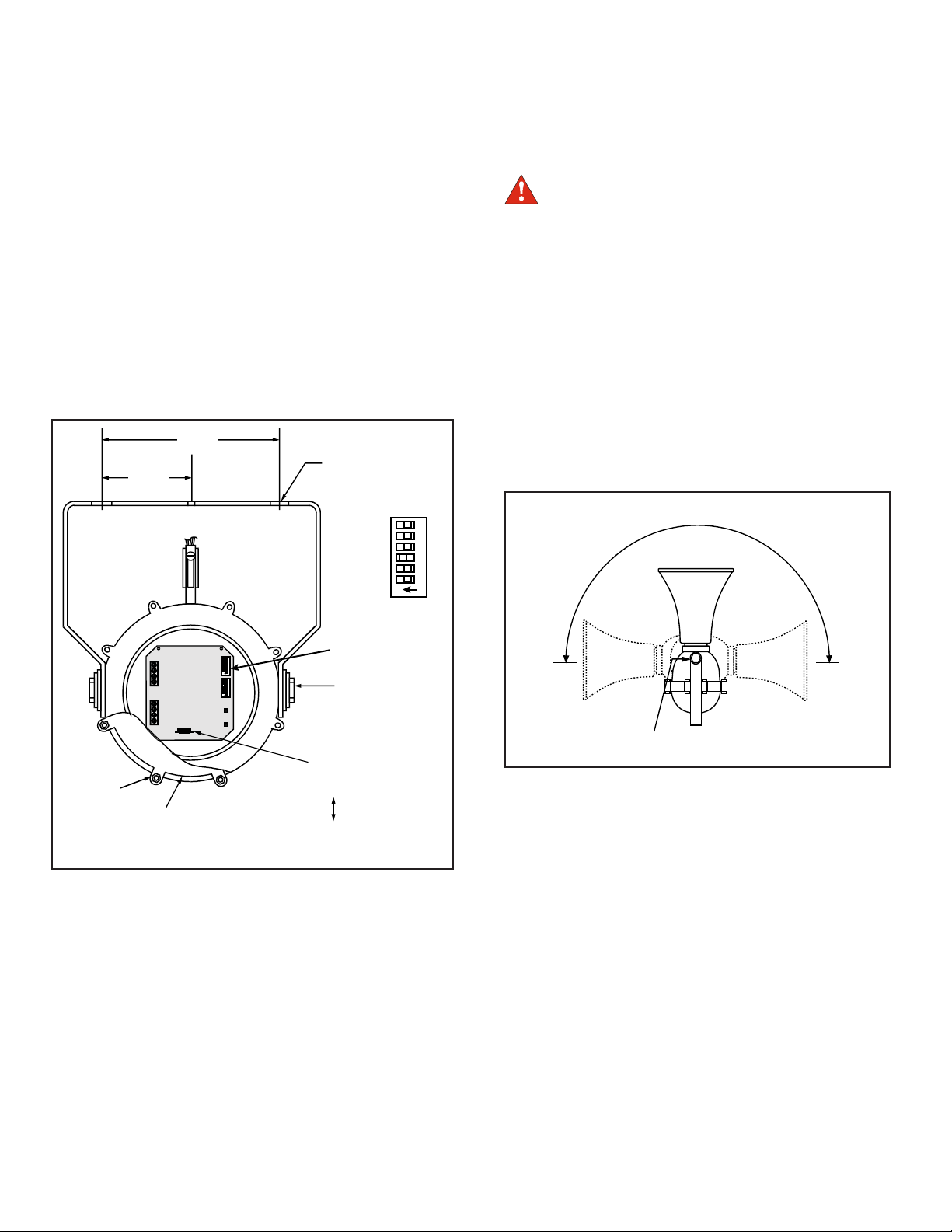
3. Set miniature programming switch on the printed circuit board
(Figure 2) for the desired tone(s). Refer to tone program chart
on inside cover and Table 1.
Select one tone and set SW1 (Figure 2).
4. Check Adaptatone label for proper operation voltage. Install
power source and initiating circuit wires through a 1/2" (13
mm) conduit attached to an outlet box and nipple. The outlet
box, conduit and nipple must be suitable for the Hazardous
Location application with 1/2" (13 mm)-14 NPT threading at
conduit openings. Outlet box, conduit and nipple are not
supplied.
Remove cover from outlet box. Feed five numbered wires
through a 1/2" (13 mm)-14 NPT nipple (not supplied) into the
outlet box. Secure outlet box to Adaptatone.
WARNING
Do not apply power to the unit until installation is
completed and housing cover and outlet box cover
are secured.
Figure 1. Dimensions
Connect green ground wire to earth ground.
Wire to a supervised signaling circuit as shown in Figure 4.
Polarity must be observed.
P/N 3100793 • REV 02 • REB 21FEB13
Page 2
2
5. Secure outlet box cover.
6. The sound level is factory set to maximum. Adjust volume
level, if desired, by turning potentiometer R72 (Figure 2).
7. Adjust speaker direction by loosening (2) nuts and pivoting
speaker to desired position (Figure 3). Tighten (2) nuts.
8. Ensure mating surfaces are clean and undamaged. Secure
housing cover aligning the straight edge of the cover with the
straight edge of the housing. Torque nuts evenly in opposing
pairs to 140 to 150 in-lb. Apply power.
9. Verify operability.
5"
(127 mm)
(3) MOUNTING
2-1/2"
(63 mm)
HOLES
654321
ON
DETAIL A
PROGRAMMING
TB1
TB2
(8) NUTS
(8) BOLTS
HOUSING COVER
NOTE: FOR CLARITY, ONLY SELECTED COMPONENTS ARE SHOWN.
SW2
SW1
SPKR (+)
SPKR (-)
654321
ON
654321
ON
SWITCHES
(SEE DETAIL A)
(2) NUTS,
LOOSEN TO
ADJUST
SPEAKER
DIRECTION
R72, TURN
TO ADJUST
SOUND LEVEL
INCREASE
DECREASE
Maintenance and Test
WARNING
Do not apply power to the unit until installation is
completed and housing cover and outlet box cover are
secured.
Examine the unit semi-annually for external accumulation of dirt.
Clean if necessary.
The Adaptatone should be tested annually or as required by the
local authority having jurisdiction to ensure continuous service.
HORN PIVOTS 180°
(2) NUTS, LOOSEN TO ADJUST
SPEAKER DIRECTION
Figure 3. Speaker Adjustment
Figure 2. Adaptatone PC Board and Mounting Holes,
5533M-AQ Model Shown
Page 3

Alarm mode shown below. On a
supervised notification appliance circuit,
the signal sounds when polarity of signal
source voltage reverses from that of
supervisory mode.
WARNING
Do not apply power until installation is
complete and housing covers are secure.
Installation and Operation
Cat. No. 5533MD-AW
Use instructions furnished with fire
alarm systems and those on this figure
to ensure correct installation.
3
*The outlet box, conduit and nipple must be suitable for hazardous location applications.
Figure 4. Wiring of 5533MD-AW Adaptatone to Supervised Signaling Circuits
Page 4

4
Figure 15. Tone Programming
SWITCH POSITIONS 6 5 4 3 2 1 DESCRIPTION HEX
No Tone 00
Ding Dong
Warble
Siren
Stutter
Slow Whoop
Beep
Chime 1
Fast Whoop
Hi/Lo
Rapid Siren
Yeow
Horn
Air Horn
Dual Tone
Chime 2
Westminster
Three Blind Mice
Phasor
Telephone
Staircase
3 Tone Alert
RESERVED
RESERVED
RESERVED
RESERVED
RESERVED
NFPA Whoop
3 Pulse Horn*
3 Pulse Air Horn*
3 Pulse Dual Tone*
3 Pulse Chime 2*
European Police
European Fire
European Slow Whoop
European General
European Toxic
European Police 2
European Stutter
European Sweep
Telephone 2
Buzzer
Genesis Horn Cont.
Genesis Horn Temp.
Warning 1
Warning 2
Warning 2 Beep
Caution
Multi-tone
Attention
High Freq. Steady Alert
High Freq. Fast Siren
High Freq. Slow Siren
DIN PFEER
NFS 32 001
Ode to Joy
Twinkle Little Star
Dueling Banjos
La Cucaracha
Yellow Rose of Texas
*3 Pulse Tones are for Evacuation Use Only.
Percussive pairs of 700 and 570 Hz tones each damped to zero
575 and 770 Hz alternately, 87 ms each
600-1250 Hz up and down sweep in 8 seconds and repeat
Percussive 470 Hz, 83 ms on, 109 ms off
600-1250 Hz upward sweep in 4 seconds and repeat
470 Hz, 0.55 seconds on, 0.55 seconds off
700 Hz percussive repeat at 1 Hz
600-1250 Hz upward sweep in 1 second and repeat
780 to 600 Hz alternately, 0.52 seconds each
600-1250 Hz up and down sweep in 0.25 seconds and repeat
1250 - 600 Hz downward sweep in 1.6 seconds and repeat
470 Hz continuous
370 Hz continuous
450 - 500 Hz, 0.4 to 0.5 second cycle
575 Hz percussive repeat at 1 Hz
Two measures: 411 Hz, 520 Hz, 407 Hz, 312 Hz
Four measures: 787 Hz, 714 Hz, 625 Hz, 952 Hz, 333 Hz
416 - 625 Hz up and down sweep in 13 ms and repeat
570 and 770 Hz alternately, 50 ms each for 1.2s, 1.5 s delay and repeat
440 - 2000 Hz up and down steps, 750 ms delay and repeat
463, 641 and 896 Hz, 200 ms each 1 second delay and repeat
RESERVED
RESERVED
RESERVED
RESERVED
RESERVED
Three 422 - 775 Hz upward sweeps, 850 ms each, 1s delay and repeat
470 Hz, 3 0.5s pulses separated by 0.5s followed by 1.5s delay and repeat
370 Hz, 3 0.5s pulses separated by 0.5s followed by 1.5s delay and repeat
450 - 500 Hz, 0.4 to 0.5s cycle, 3 0.5s pulses separated by 0.5s followed by
1.5s delay and repeat
575 Hz, 3 0.5s pulses separated by 0.5s followed by 1.5s delay and repeat
969 Hz and 800 Hz alternately 0.250 seconds each
982 Hz and 864 Hz downward sweep in 0.134 seconds
658 Hz to 1312 Hz upward sweep in 3s followed by 0.5s delay and repeat
1087 Hz for 0.5 seconds followed by 0.5 second delay and repeat
982 Hz continuous
554 Hz and 440 Hz alternately 0.800 seconds each
3876 Hz for 0.146 seconds followed by 0.102 seconds delay and repeat
1315 Hz to 413 Hz downward sweep in 1.17 seconds and repeat
Alternate tones at 567 Hz and 326 Hz, for 0.052 seconds each
1315 Hz to 746 Hz alternating for 0.003 seconds each
Continuous Genesis horn
Temporal Genesis horn
1207 Hz and 493 Hz, alternately 0.002 seconds each
2336 Hz and 493 Hz, alternately 0.005 seconds each
0.500s of 2336 Hz and 493 Hz each alternating for 0.005s followed by 1s delay
453 Hz for 0.040s, 235 Hz for 0.020s, 235 Hz for 0.160s, 260 Hz for 0.050s,
260 Hz for 0.1009s, 235 Hz for 0.050s
376, 357, 352, 382, 355, 375, 384, 375 and 364 Hz alternately on for 0.050s
2232, 4545, 3704, 2777, 4347, 3704, 2500 Hz alternately on for 0.003s
2500 Hz continuous
2500 to 3048 Hz up and down sweep in 0.130 seconds
2500 to 3048 Hz up and down sweep in 0.500 seconds
Ramp downward from 1336 Hz to 522 Hz in 1.2 seconds and repeat
584 Hz for 0.100 seconds and 461 Hz for 0.400 seconds
6.45 seconds of melody followed by 1 second delay and repeat
13.2 seconds of melody followed by 1 second delay and repeat
10.84 seconds of melody followed by 1 second delay and repeat
7.10 seconds of melody followed by 1 second delay and repeat
19.34 seconds of melody followed by 1 second delay and repeat
CAUTION
Closed / On Switch =
Open / Off Switch =
6 5 4 3 2 1
The use of evacuation signals on this product, that is
not specifically Listed for Fire Alarm Use, is subject to
the approval of the Authority Having Jurisdiction.
01
02
03
04
05
06
07
08
09
0A
0B
0C
0D
0E
0F
10
11
12
13
14
15
16
17
18
19
1A
1B
1C
1D
1E
1F
20
21
22
23
24
25
26
27
28
29
2A
2B
2C
2D
2E
2F
30
31
32
33
34
35
36
37
38
39
3A
3B
 Loading...