

Page 1

517FH Series 135°F Fixed Temperature Heat Detector
AC Powered, 120V 60 Hz with Battery Backup
Installation Instructions - Owner's/User's Information Manual
READ CAREFULLY AND SAVE
INTRODUCTION
The 517FH Heat Detector is for use as an evacuation device in
residential applications. Each alarm has a solid state piezo that
emits a temporal 3 signal to warn and alert the household to the
presence of threatening heat.
Your alarm is designed to detect heat that results from an actual fire. Heat detectors are intended for use as supplements to
smoke alarms. This unit cannot detect smoke or other toxic gases,
therefore, do not rely solely on this heat detector to provide a warning of a fire.
NOTE: In the event AC Power fails, a 9v battery will provide proper
alarm operation for a minimum of a 24-hour period.
HOW TO TELL IF YOUR HEAT DETECTOR IS WORKING PROPERLY
• Your detector is provided with an alarm horn and pulsating Light
Emitting (indicator) Diode, which pulses every 30 seconds, and
a green AC power on LED.
• If the battery is low, a chirp will be emitted when the red LED
flashes. If the alarm is malfunctioning, or if the battery is missing, the chirp is sounded without the red LED flashing. If AC
power fails, the green LED will turn off.
• To test your heat detector, direct a hair dryer at the sensor ele-
ment (silver disk) at a 4-6” distance. Alternatively, a cordless
soldering iron may be applied to sensor element. The unit will
return to normal standby mode once the disk cools down. A
cold damp rag or sponge may used to quickly cool the sensor.
NOTE: Tandem Interconnect Models.
• When testing one alarm, the alarm that is activated will flash the
red indicator light and sound its alarm horn. All other units will
sound the alarm horn with their red indicator lights remaining
off. The relays will also activate on all units in tandem on models equipped with the relay option.
FIRE PROTECTION PLAN
Please note that there are hazards against which heat detection
may not be effective, such as smoking in bed, explosions, when a
closed door separates the alarm from the source of the fire, etc.
The ultimate responsibility for fire protection rests solely on you.
1. To minimize fire hazards—avoid improper storage of flammable
liquids and don’t leave small children home alone.
2. Bedroom doors should be closed while sleeping if a smoke
alarm is installed in the bedroom. They act as a barrier against
heat and smoke.
3. Establish an escape plan:
(a) Post a detailed floor plan depicting the chosen escape
routes.
(b) Each bedroom should have at least two escape routes.
(c) Make sure your children know what to do in case of fire
and teach them to follow the escape plan you have posted.
(d) Agree on an outside meeting place.
(e) Conduct fire drills at least twice a year.
(f) Be sure each member of the family is familiar with the
smoke alarm so they can react properly.
If the alarm should sound:
1. Never waste time dressing or gathering valuables. Follow the
escape route and leave the house immediately.
2. Check bedroom doors before opening. If the door is hot or
smoke is leaking in around the edges—DO NOT OPEN—use
the alternate escape route.
3. If there is smoke in the escape route—keep close to the floor
and take short breaths. If possible, cover your nose and mouth
with a wet cloth.
4. Do not use your own telephone—call the Fire Department from
your neighbor’s house.
5. Once out, do not re-enter your house, but proceed to your
prearranged meeting place.
WHAT ELSE YOU CAN DO TO MAKE
YOUR FAMILY SAFE FROM FIRES
Putting up heat detectors and smoke alarms is just the first step
in protecting your family from fires. You also must reduce the
chances that fires will start in your home and increase your chances
of safely escaping if one does start. To have an effective fire safety
program:
a. Install smoke alarms and heat detectors properly follow-
ing the instructions in the product’s manual. Keep your
alarms clean. Test your alarm monthly and repair or replace it when it no longer functions. As with any electronic
product, alarms have a limited life, and alarms that don’t work
cannot protect you.
b. Follow safety rules and prevent hazardous situations:
• Use smoking materials properly; never smoke in bed.
• Keep matches and cigarette lighters away from children.
• Store flammable materials in proper containers and never use
them near open flames or sparks.
• Keep electrical appliances and cords in good working order
and do not overload electrical circuits.
• Keep stoves, fireplaces, chimneys, and barbecue grills greasefree and make sure they are properly installed away from combustible materials.
• Keep portable heaters and open flames such as candles away
from combustible materials.
• Do not allow rubbish to accumulate.
c. Develop a family escape plan and practice it with your
entire family, especially small children.
••
• Draw a floor plan of your home and find two ways to exit from
••
each room. There should be one way to get out of each bedroom without opening the door.
••
• Teach children what the smoke alarm or heat detection signal
••
means, and that they must be prepared to leave the residence
by themselves if necessary. Show them how to check to see
if doors are hot before opening them, how to stay close to the
floor and crawl if necessary, and how to use the alternate exit
if the door is hot and should not be opened.
CHESHIRE, CT 203-699-3300 F AX 203-699-3365
P/N 550-0175-000 © 1999
Page 2

••
• Decide on a meeting place a safe distance from your house
••
and make sure that all your children understand that they
should go and wait for you if there is a fire.
••
• Hold fire drills at least every 6 months to make sure that ev-
••
eryone, even small children, knows what to do to escape safely.
••
• Know where to go to call the fire department from outside
••
your residence.
••
• Provide emergency equipment such as fire extinguishers and
••
teach your family to use this equipment properly.
WHAT TO DO IF THERE IS A FIRE
IN YOUR HOME
If you have prepared family escape plans and practiced them
with your family, you have increased their chances of escaping
safely. Review the following rules with your children when you
have fire drills so everyone will remember them in a real fire emergency:
a. Don’t panic; stay calm. Your safe escape may depend on
thinking clearly and remembering what you have practiced.
b. Get out of the house following a planned escape route as
quickly as possible. Do not stop to collect anything or to get
dressed.
c. Open doors carefully only after feeling to see if they are hot.
Do not open a door if it is hot; use an alternate escape route.
d. Stay close to the floor; smoke and hot gases rise.
e. Cover your nose and mouth with a cloth, wet if possible, and
take short, shallow breaths.
f. Keep doors and windows closed unless you open them to es-
cape.
g. Meet at your prearranged meeting place after leaving the house.
h. Call the Fire Department as soon as possible from outside
your house. Give the address and your name.
i. Never re-enter a burning building.
Contact your local Fire Department for more information on
making your home safer from fires and about preparing your
family’s escape plans.
WHAT THIS HEAT DETECTOR
CAN DO
This alarm is designed to sense heat produced by a fire. IT
WILL NOT SENSE SMOKE OR OTHER TOXIC GASES.
When properly located, installed, and maintained, this heat detector is designed to provide warning of developing fires at a reasonable cost. This alarm monitors the air and, when it senses
heat, activates its built-in alarm horn. NOTE: This heat detector
is designed for use within single residential living units only; that
is, it should be used inside a single-family home or one apartment
of a multi-family building. In a multi-family building, the alarm
may not provide early warning for residents if it is placed outside
of the residential units, such as on outside porches, in corridors,
lobbies, basements, or in other apartments. In multi-family buildings, each residential unit should have alarms to alert the residents of that unit. Alarms designed to be interconnected should
be interconnected within one family residence only; otherwise,
nuisance alarms will occur when an alarm in another living unit is
tested.
IMPORTANT NOTE: WHAT HEAT DETECTORS CANNOT DO
Heat Detectors will not work without power. A battery must
be connected to the alarm to maintain proper alarm operation if
AC power supply is cut off by an electrical fire, an open fuse or
circuit breaker, or for any other reason. In the event of AC power
failure, the battery will supply power for a minimum of 24 hours.
Heat detectors may not sense fire that starts where heat
cannot reach the alarms such as in chimneys, in walls, on roofs,
or on the other side of closed doors. Smoke alarms should also
be placed in each bedroom as well as in the common hallway
between them.
Heat detectors also may not sense a fire on another level
of a residence or building. For example, a second-floor alarm
may not sense a first-floor or basement fire. Therefore, alarms
should be placed on every level of a residence or building.
The horn in your alarm meets or exceeds current audibility re-
quirements of Underwriters Laboratories. However, if the alarm
is located outside a bedroom, it may not wake up a sound
sleeper, especially if the bedroom door is closed or only partly
open. If the alarm is located on a different level of the residence
than the bedroom, it is even less likely to wake up people sleeping
in the bedroom. In such cases, the National Fire Protection Association recommends that the alarms be interconnected so that an
alarm on any level of the residence will sound an alarm loud enough
to awaken sleepers in closed bedrooms. This can be done by
installing a fire-detection system, by connecting alarms together,
or by using radio frequency transmitters and receivers.
All types of smoke alarm and heat detector sensors have
limitations. No type of smoke alarm and heat detector can
sense every kind of fire every time. In general, alarms may
not always warn you about fires caused by violent explosions,
escaping gas, improper storage of flammable materials, or
arson.
NOTE: This detector is not designed to replace special-purpose fire detection and alarm systems necessary to protect persons and property in non-residential buildings such as warehouses,
or other large industrial or commercial buildings. It alone is not a
suitable substitute for complete fire-detection systems designed
to protect individuals in hotels and motels, dormitories, hospitals,
or other health and supervisory care and old age institutions.
Please refer to NFPA 101,The Life Safety Code, and NFPA 72 for
smoke alarm requirements for fire protection in buildings not defined as “households.”
Installing smoke alarms and heat detectors may make you eligible for lower insurance rates, but smoke alarms and heat de-
tectors are not a substitute for insurance. Homeowners and
renters should continue to insure their lives and property.
HEAT DETECTION
General. - While Chapter 2 of NFPA 72 does not require heat
detectors as part of the basic protection scheme, it is recommended
that the householder consider the use of additional heat detectors
for the same reasons presented in the next section. The additional areas lending themselves to protection with heat detectors
are the kitchen, dining room, attic (finished or unfinished), furnace room, utility room, basement and integral or attached garage. For bedrooms, the installation of a smoke alarm is recommended over the installation of a heat detector for protection of
the occupants from fires in their bedrooms.
Heat Detector Mounting – Dead Air Space. Heat from a fire
rises to the ceiling, spreads out across the ceiling surface, and
begins to bank down from the ceiling. The corner where the ceiling and the wall meet is an air space into which heat has difficulty
penetrating. In most fires, this dead air space measures about 4
in. (0.1 m) down the wall as shown in Fig. 5. Heat detectors
should not be placed in this dead air space.
The placement of the detector is critical where maximum speed
of fire detection is desired. Thus, a logical location for a detector
is the center of the ceiling. At this location, the detector is closest
to all areas of the room.
If the detector cannot be located in the center of the ceiling, an
off-center location on the ceiling may be permitted to be used.
Page 3
The next logical location for mounting detectors is on the
sidewall. Any detector mounted on the sidewall should be located
as near as possible to the ceiling. A detector mounted on the
sidewall should have the top of the detector between 4 in. and 12
in. (0.1 m and 0.3 m) from the ceiling.
The Spacing of Detectors. Where a room is too large for protection by a single detector (50ft. spacing), several detectors should
be used. It is important that they be properly located so all parts
of the room are covered.
Where the Distance Between Detectors Should Be Further Reduced. The distance between detectors is based on data obtained
from the spread of heat across a smooth ceiling. Where the ceiling is not smooth, the placement of the detector should be tailored to the situation.
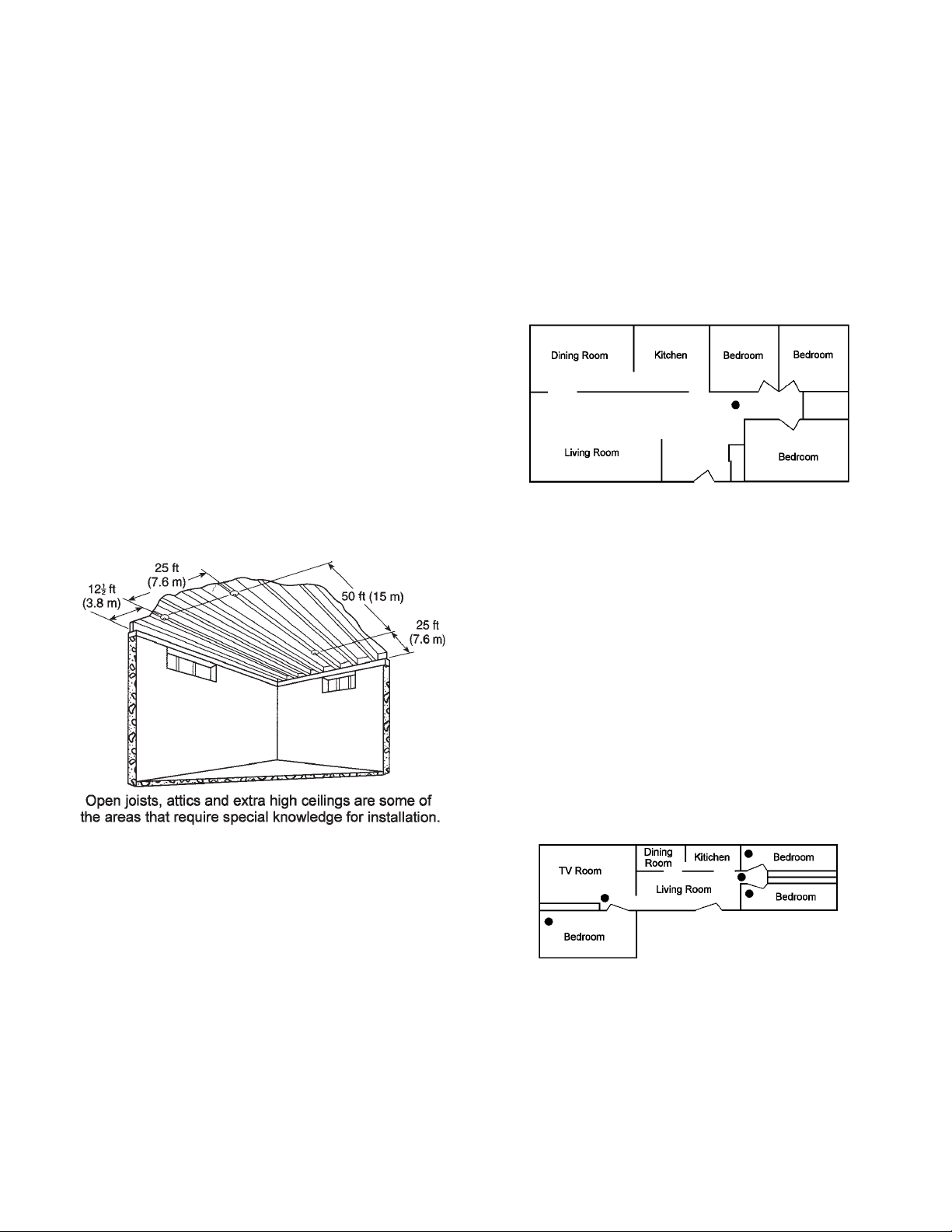
For instance, with open wood joists, heat travels freely down
the joist channels so that the maximum distance between detectors, 50 ft. (15 m), may be permitted to be used. However, heat
has trouble spreading across the joists, so the distance in this
direction should be ½ the distance allowed between detectors, as
shown in fig. 1, and the distance to the wall is reduced to 12 ½ ft.
(3.8 m). Since ½ x 50 ft. (15 m) is 25 ft. (7.6 m), the distance
between detectors across open wood joists should not exceed 25
ft. (7.6 m), as shown in fig. 1, and the distance to the wall is
reduced [ ½ x 25 ft. (7.6 m)] to 12.5 ft. (3.8 m). The detectors are
required to be mounted on the bottom of the joists and not up in
joist channels.
Walls, partitions, doorways, ceiling beams and open joists interrupt the normal flow of heat, thus creating new areas to be
protected.
In family living units with more than one bedroom area or with
bedrooms on more than one floor, more than one smoke alarm
will be needed, as shown in Figure 3.
In addition to smoke alarms outside of the sleeping areas, Chapter 2 of NFPA 72 requires the installation of a smoke alarm on
each additional story of the family living unit, including the basement. These installations are shown in Figure 4. The living area
smoke alarms should be installed in the living room or near the
stairway to the upper level, or in both locations. The basement
smoke alarm should be installed in close proximity to the stairway
leading to the floor above. When installed on an open joisted
ceiling, the alarm should be placed on the bottom of the joists.
The alarm should be positioned relative to the stairway so as to
intercept smoke coming from a fire in the basement before the
smoke enters the stairway.
Figure 2: A SMOKE ALARM SHOULD BE LOCATED BETWEEN
THE SLEEPING AREA AND THE REST OF THE FAMILY LIVING
UNIT.
Where to Locate the Required Smoke Alarms in New Con-
struction. All of the smoke alarms specified for existing construc-
tion are required, and, in addition, a smoke alarm is required in
each bedroom.
Are More Smoke Detectors Desirable? The required number
of smoke alarms may not provide reliable early warning protection for those areas separated by a door from the areas protected
by the required smoke alarms. For this reason, it is recommended
that the householder consider the use of additional smoke alarms
for those areas for increased protection. The additional areas
include: basement, bedrooms, dining room, furnace room, utility
room and hallways not protected by the required smoke alarms.
The installation of smoke alarms in kitchens, attics (finished or
unfinished), or garages is not normally recommended, as these
locations occasionally experience conditions that can result in
improper operation.
Fig. 1
PLACEMENT OF SMOKE ALARMS
For your information, the National Fire Protection Association’s
Standard 72, reads as follows:
“2-2.1.1.1 Smoke detectors shall be installed outside of each
separate sleeping area in the immediate vicinity of the bedrooms
and on each additional story of the family living unit including basements and excluding crawl spaces and unfinished attics. In new
construction, a smoke detector shall be installed in each sleeping
room.”
Where to Locate the Required Smoke Detectors in Existing Con-
struction. The major threat from fire in a family living unit is at
night when everyone is asleep. The principal threat to persons in
sleeping areas comes from fires in the remainder of the unit; therefore, a smoke alarm(s) is best located between the bedroom areas and the rest of the unit. In units with only one bedroom area
on one floor, the smoke alarms should be located as shown in
Figure 2.
Figure 3: IN FAMILY LIVING UNITS WITH MORE THAN ONE
SLEEPING AREA, A SMOKE ALARM SHOULD BE PROVIDED
TO PROTECT EACH SLEEPING AREA IN ADDITION TO
ALARMS REQUIRED IN BEDROOMS.
Page 4

Figure 4: A SMOKE ALARM SHOULD BE LOCATED ON EACH
STORY.
IMPORTANT CONSIDERATION
We recommend replacing your alarm(s) every ten (10) years;
why:
• Dust, dirt, and other environmental contaminants can affect your
alarm over a prolonged period.
• Fast changing industry consensus standards and codes on all
alarms make it advisable to periodically upgrade your alarm to
maximize life safety.
• Assurance that your smoke alarm and/or heat detector needs
are kept abreast with the constantly improving electronic technology.
• Smoke alarms and heat detectors are recognized as one of the
lowest cost ways to protect dwelling inhabitants against the danger of fire(s). It makes good common sense to periodically replace and update your smoke alarm and/or heat detector that
contributes so much to life safety.
MOUNTING LOCATION
This heat detector can be mounted on a ceiling or wall with
equal efficiency in either location.
• Ceiling location—alarm should be mounted as close as pos-
sible to the center of a hallway or room. If this is not possible,
the edge of the alarm should be at least 4 inches from any wall.
• Wall location—locate the top of the alarm at least 4 inches and
not more than 12 inches from the ceiling.
The placement of the detector is critical if maximum speed of
fire detection is desired. Thus, a logical location for a detector is
the center of the ceiling. At this location, the detector is closest to
all areas of the room.
LOCATIONS TO AVOID
Placing detectors where they will not operate properly causes
nuisance alarms. To avoid nuisance alarms, do not place heat
detectors:
••
• Where temperatures are regularly below 0oF (-31oC) or above
••
110oF (43oC).
••
• In air streams passing by kitchens. It is possible normal air
••
currents can draw cooking heat into the sensor of a unit near the
kitchen. If you experience frequent unwanted alarms from a unit
near your kitchen, try relocating it. Do not install your heat detector over a stove or a range.
••
• In dead air spaces at the top of a peaked roof or in the cor-
••
ners between ceilings and walls. Dead air may prevent heat
from reaching a detector. See Figures 1 and 5 for recommended
mounting locations.
••
• Near fluorescent light fixtures. Electrical “noise” from nearby
••
fluorescent light fixtures may cause a nuisance alarm. Install
alarms at least 5 feet (1.5 meters) away from such light fixtures.
WARNING: Never disconnect an AC alarm to silence a nuisance
alarm. Use a cold damp rag or sponge and apply to the heat
sensor (silver disk) on the face of the unit. The detector will
automatically turn off when the temperature of the sensor falls
below 135oF. Do not unnecessarily stand close to the alarm. The
sound produced by the alarm is loud because it is designed to
awaken you in an emergency. Prolonged exposure to the horn at
a close distance may be harmful to your hearing.
INSTALLATION
CAUTION: New Construction: DO NOT attach alarm head until
AFTER sanding, painting, and other dust creating situations are
finished and cleaned up.
WIRING/GENERAL
1. Use U.L. Listed cable with Class1 insulation.
2. Observe local code requirements. Use box connector to an-
chor cable to outlet box.
3. Metal outlet boxes must be grounded to earth ground.
4. Use only Duracell MN 1604 battery or Eveready 522 battery
with the 517FH detector.
CAUTION: Turn off electricity to prevent SHOCK and damage to
alarm. Be sure the power line to the alarm is not controlled by any
on/off switch, or other type of switch, other than a fuse or circuit
breaker.
IMPORTANT: Insure that all fluorescent lighting fixtures are properly grounded.
WARNING: Alarm installation must conform to the electrical
codes in your area and to Article 760 of the U.S. National Electrical Code. Wire installation should be performed only by a licensed
electrician.
Figure 5: RECOMMENDED HEAT DETECTOR MOUNTING LOCATIONS
MOUNTING OUTLET BOX
Use a 2” x 3” switch box or a 4” square or octagon junction box.
Mount a box for each alarm. If wall mounting is desired, be sure
the box screws are oriented to upper right and lower left corners.
Be sure to use supplied Mounting Plate.
Page 5

WIRING ONE DETECTOR
1. Run a minimum of 16 gauge, 2-conductor cable, plus ground
(3 wires) to the alarm junction box from a power supply. Use
UL Listed Class 1 wire.
2. Make wire connections to the supplied plug-in connector as
follows: black to black, white to white, and connect the ground
wire to the metal outlet box.
NOTE/RED-YELLOW WIRE: The red-yellow wire from the alarm
is for tandem connection only. DO NOT USE, AND DO NOT
REMOVE INSULATION CAP UNLESS CONNECTING ANOTHER
ALARM.
WIRING TWO OR MORE DETECTORS
Tandem Installation
CAUTION: All alarms in a tandem installation must be con-
trolled by the same fuse or circuit breaker. Otherwise tandem
units will not operate. Tandem will operate in the event of AC
power failure if battery is connected to the alarm.
LIMITATIONS: A maximum of (12) smoke alarms (517TB or
517T) may be connected together. A total or (18) heat and smoke
detectors may be connected together. Do not exceed 125 feet
between each alarm. Do not exceed 1125 feet between first and
last alarm.
NOTE: A maximum of five (5) alarms of either model 517TCB
or 517TC with the relay options or 517TCS or 517TCSB may be
tandem interconnected with up to (3) heat detectors.
Wire used for interconnecting shall be in accordance with the
latest editions of article 760 of the National Electrical Code (NFPA
70) and must not exceed a resistance of 10 ohms.
1. Run a minimum of 16 gauge, 3-conductor cable, plus ground
(4 wires) to the first alarm junction box from a power supply
and between all alarms that are to be connected together. Use
UL Listed Class 1 wire.
2. Make wire connections to the supplied plug-in connector as
follows: black to black, white to white, 3rd conductor to the
red/yellow wire. The red/yellow wire should be stripped to make
the connection. Connect ground wire between metal outlet
boxes.
NOTES ON TANDEM INTERCONNECTING MODELS
• DO NOT connect Edwards Smoke Alarms or Heat Detectors to
other manufacturers’ smoke alarms.
• No more than (12) Edwards models 517TB, 517THB, 517T or
518TH may be connected in tandem with (6) models 517FH.
• No more than (6) Edwards models 517TCS or 517TCSB may
be connected in tandem. If a 517FH is interconnected, a maximum of (5) 517TCS or 517TCSB and (3) 517FH units may be
interconnected.
• All units connected in tandem MUST get their power from the
same circuit, that is, all smoke alarms in tandem must be controlled by the same fuse or circuit breaker.
• After installation to verify proper working conditions all horns
must sound in this system.
IMPORTANT WARNING:
Failure to observe any of the conditions set forth may cause
system malfunction and damage to the alarm.
BATTERY INSTALLATION
1. Remove alarm from mounting plate by turning counter-clockwise.
2. Remove AC power connector and unsnap power leads from
the top of the old battery. Snap new battery onto snaps and
reinsert battery through hole in the back of the alarm. WARNING: Units with battery back-up will not provide power or transmit an alarm to AC only units in the event of an AC power
failure. All battery back-up units in tandem with good batteries will operate normally during an AC power failure.
Page 6

MOUNTING: PLATE & ALARM
1. Lace the connector through the provided mounting plate and
secure the plate to the junction box.
2. Plug the wire connector into the alarm base.
3. Place the alarm up to the mounting plate, rotating it clockwise
until alarm firmly snap locks into place. Keep the alarm parallel to the mounting plate so upper and lower tabs on the plate
seat correctly into the alarm.
TESTING
Use a hair dryer and direct hot air towards the silver disk on the
face of the detector or use a portable soldering iron and place it
against the heat sensor. Testing should be conducted semiannually.
WARNING: Never use an open flame of any kind to test your
detector. You may ignite and damage the detector as well as
your home
LIMITED WARRANTY
Providing Purchaser or Distributor notifies us promptly if within two (2) years from date of
shipment from Edwards Company, equipment or parts manufactured by us fail to function
properly under normal use because of defects in material or workmanship demonstrated
to our satisfaction to have existed at the time of delivery or because examination proves
them not to be operating within the specified limit of calibration, the Company, reserving
the right to either inspect them in your hands or request their return to us, will at our
option repair or repace at our expense F.O.B. shipping point, such equipment or parts
determined by us to be defective, if returned transportation prepaid by Purchaser. Specific
products may carry a greater or lesser warranty but if so they will be so identified.
Replacement parts and factory repairs are warranted for a period of ninety (90) days from
date of shipment from the Edwards Company.
The foregoing shall not apply to equipment that shall have been altered or repaired after
shipment to you by anyone except our authorized employees or agents and the Company
will not be liable in any event for alterations or repairs except those made with its written
consent. Purchaser shall be solely responsible for determining suitability for use and the
Edwards Signaling
90 Fieldstone Court, Cheshire, CT 06410
Phone: 1-203-699-3300
Company shall in no event be liable in this respect. The equipment or parts manufactured
by others but furnished by us will be repaired or replaced only to the extent of the original
manufacturer's guarantee. No guarantee whatsoever is given as to electronic tubes, and
the Company shall have no repair or replacement obligations as to these. Our obligations
and liaibilities hereunder shall not be enforceable until such equipment has been fully paid
for. Purchaser agrees that if the products sold hereunder are resold by purchaser, he will
include in the contract for resale, provisions which limit recoveries against us in accordance
with this section. THE FOREGOING OBLIGATIONS ARE IN LIEU OF ALL OTHER OBLIGATIONS
AND LIABILITIES INCLUDING NEGLIGENCE AND ALL WARRANTIES OF MERCHANTABILITY
OR OTHERWISE, EXPRESS OR IMPLIED IN FACT OR BY LAW, AND STATE OUR ENTIRE AND
EXCLUSIVE LIABILITY AND BUYER'S EXCLUSIVE REMEDY FOR ANY CLAIM OF DAMAGES
AND IN CONNECTION WITH THE SALE OR FURNISHING OF GOODS OR PARTS, THEIR DESIGN,
SUITABILITY FOR USE, INSTALLATION OR OPERATION. WE WILL IN NO EVENT BE LIABLE
FOR ANY DIRECT, SPECIAL OR CONSEQUENTIAL DAMAGES WHATSOEVER, AND OUR
LIABILITY UNDER NO CIRCUMSTANCES WILL EXCEED THE CONTRACT PRICE FOR THE
GOODS FOR WHICH LIABILITY IS CLAIMED.
 Loading...