

Page 1
Edwards® 2440S & 2441S Series
Strobe Signals
Features
• Low current draw synchronous
strobe
• Supervised wiring
• Terminals for easy wiring
• Red or white flame resistant
housing
• Strobe available in 15, 30, 60, 15/75,
and 110 candela models
• Control modules not required
Description
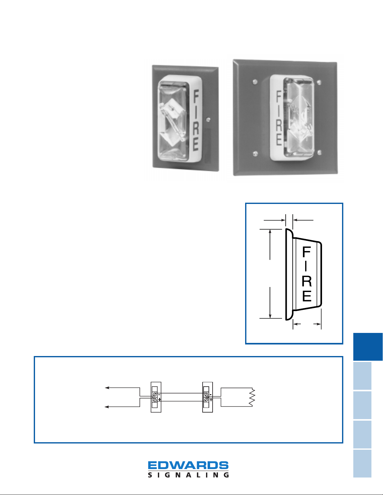
The Edwards 2440S & 2441S Series
synchronous strobes are visual alarm
signals designed for use in fire alarm
applications.
The strobes employ a unique microprocessor design that assures all units
operate at the same time and at a
rate of one flash per second thereby
reducing the risk of causing disorientation of a small portion of the population having photosensitivity.
Screw terminals are provided for
easy installation. The strobes require
a continuous (non-pulsed) DC source.
Agency Approvals
• Strobe: UL 1971 Listed for the
Hearing Impaired
• Strobe: UL 1638 Listed Private
Mode (Indoor and not for the hearing impaired)
• Meets NFPA and ADA require-
ments
• Engineered thermoplastic housing
UL flame rated 94V-0
Specifications
• See Specification Information Table
on page 12-24.
Installation
See Strobe Application Data, page
12-38, for the following: sizing wall
and ceiling mounted strobes to room
size, mounting strobes in corridors,
and mounting strobes in sleeping
rooms.
See System Design Criteria on page
12-51.
Applications
The 2440S & 2441S series strobe is a
visual signaling appliance for installations that operate in conjunction with
an installed fire alarm panel and detection devices.
Cat. No. 2440S
Cat. No. 2441S
5"
(127mm)
1 7/8"
(48mm)
1/4"
(6mm)
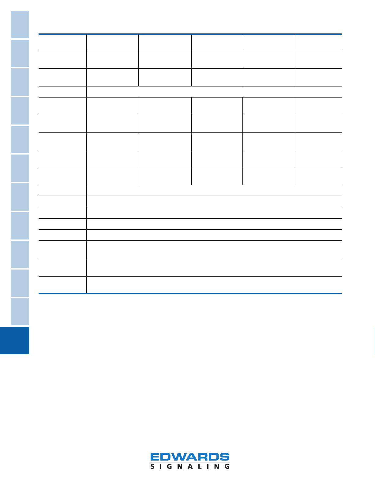
Equipment
Fire Alarm
Polarity of signal circuit shown in supervisory state. On alarm, polarity reverses. For wiring installation details, see the applicable
control panel installation manual.
+
To Listed Fire Alarm Control Panel
(signal circuit)
End-of-line-resistor
(supplied with control panel)
-
CAUTION: This unit is designed to be used on signal circuits that output a constant voltage of 20-24V DC. Do not connect this unit
to a coded or pulsating voltage. Electrical supervision requires wire run to be broken at each terminal. Do not loop signaling circuit field wires around terminals.
12-23
Fax-on-Demand # 1170
Clocks
ADA/Hospital
Signaling
Devices
Accessories
Telephone
Signals &
Appendix
Page 2
Signals
Control
Process
NEMA &
Hazardous,
IP Definitions
Visual
Signals
Signals
Electronic
Bells &
Buzzers
Sirens
Horns &
Specification Information
Catalog Number 2440S-15-(†) 2440S-30-(†) 2440S-60-(†) 2440S-15/75-(†) 2440S-110-(†)
2441S-15-(†) 2441S-30-(†) 2441S-60-(†) 2441S-15/75-(†) 2441S-110-(†)
UL 1638 Strobe Not UL 1638 Rated 30 cd 60 cd 75 cd 120 cd
Flash Output
UL 1971 Strobe 15 cd 30 cd Wall 60 cd Wall 15 cd Wall 110 cd Wall
Flash Output (Wall Mount Only) 15 cd Ceiling 30 cd Ceiling 15 cd Ceiling 60 cd Ceiling
Operating Voltage 20 to 24V DC Continuous (Non-pulsed)
Avg. Operating 70 mA @ 24V DC 105 mA @ 24V DC 160 mA @ 24V DC 105 mA @ 24V DC 219 mA @ 24V DC
Current (1,4) 79 mA @ 20V DC 125 mA @ 20V DC 190 mA @ 20V DC 125 mA @ 20V DC 272 mA @ 20V DC
Peak Operating 125 mA @ 20V DC 185 mA @ 20V DC 240 mA @ 20V DC 185 mA @ 20V DC 340 mA @ 20V DC
Current (1,3)
Avg. Operating 60 mA @ 24V DC 90 mA @ 24V DC 130 mA @ 24V DC 90 mA @ 24V DC 190 mA @ 24V DC
Current (2) 70 mA @ 20V DC 102 mA @ 20V DC 155 mA @ 20V DC 102 mA @ 20V DC 235 mA @ 20V DC
Peak Operating 375 mA @ 20V DC 530 mA @ 20V DC 700 mA @ 20V DC 530 mA @ 20V DC 910 mA @ 20V DC
Current (2,3)
Peak Inrush 7.6 A @ 24V DC 7.6 A @ 24V DC 7.6 A @ 24V DC 7.6 A @ 24V DC 7.8 A @ 24V DC
Current (4)
Strobe Flash Rate Synchronized at 1 flash per second (no external control module required)
Message
Centers &
Annunciators
Signals
Outdoor
Warning
Electric
Chimes
Contactors
Push Buttons
Door Devices
Transformers
Fire Alarm
Equipment
Strobe Lens Clear Lexan
Wire Connection Terminals, Polarized Input, #12 AWG
Lens Markings Red "FIRE" Vertical Both Sides (Wall Mount)
Faceplate Material Textured Color-Impregnated Noryl (Exceeds 94V-0 UL Flammability Rating)
Mounting Flush: 1-Gang (2" Deep Min.) Standard Electrical Box
Surface: 1-Gang Wiremold Box
Operating 85% Relative Humidity @ 86°F (30C); 32° to 120°F (0° to 49°C) Variable Ambient Temp.
Environment
Agency Listing UL 1971, UL 1638 and UL 464
(All models comply with ADA Code of Federal Regulation Chapter 28 Part 36 Final Rule)
† The 2440S & 2441S strobes are available with either a red faceplate or a white faceplate; for a red faceplate, put an "R" in this position
and for a white faceplate, put a "W" in this position.
Note 1: Connected to filtered DC source.
Note 2: Connected to unfiltered DC source (full wave rectified)
Note 3: Use the peak current rating to establish the maximum number of strobes, wire gauge and standby power requirements. Consult
the panel manufacturer to determine the maximum number of strobes for each signaling circuit.
Note 4: Peak inrush current at 24V DC for less than 50 microseconds.
12-24
Fax-on-Demand # 1170
Page 3

Signals
Control
Process
NEMA &
Hazardous,
IP Definitions
Visual
Signals
Signals
Electronic
Bells &
Buzzers
Sirens
Horns &
Message
Centers &
Annunciators
Signals
Outdoor
Warning
Electric
Chimes
Contactors
Push Buttons
Door Devices
Transformers
Fire Alarm
Equipment
Edwards® Strobe
Application Data
Description
The National Fire Protection Association (NFPA) has established guidelines for the installation of visual signaling appliances for rooms, corridors, and sleeping areas. These
guidelines, referenced in NFPA 72,
Chapter 6, take into consideration
the effective intensity of the strobe
light, the size of the space, and
whether the appliance is installed on
the wall or ceiling. Edwards synchronous, fire alarm strobes are listed to
UL Standard 1971 and conform to
the ADA (Americans with Disabilities
Act) equivalent facilitation when installed using these guidelines. When
employing these guidelines consult
the Authority Having Jurisdiction.
Space Allocation for Rooms
Table 1 provides the candela rating
required for strobes when installed
on walls in rooms of varying size.
When ceiling mounted, the number
of strobes may be reduced while continuing to provide equivalent facilitation. Table 2 lists room, ceiling
height, and appropriate light intensity for the given space.
Space Allocation for
Corridors
Strobes mounted in corridors not
greater than 20 feet (6.1m) wide
shall be located no more than 15
feet (4.6m) from the end of the corridor with a separation no greater
than 100 feet (30.5m) between appliances. They shall be wall mounted
in accordance with Table 3.
Space Allocation for
Sleeping Rooms
Strobes mounted on the wall with
the top of the strobe greater than
24 inches (61cm) from the ceiling
shall be rated 110 cd. Strobes closer
to the ceiling than 24 inches (61cm)
shall be rated 177 cd.
Max. Room One Light Per (On Opposite (One per Wall)
Size Room (CD) Walls) (CD) (CD)
20' x 20' 15 — —
30' x 30' 30 15 —
40' x 40' 60 30 15
50' x 50' 95 60 30
60' x 60' 135 95 30
70' x 70' 185 110 60
80' x 80' — 140 60
Note: The bottom of the wall mounted appliance should be not less than 80 inches (203cm) or more
than 96 inches (244cm) from the floor.
Max. Room Maximum Ceiling
Size Height (ft.) One Light (CD)
20' x 20' 10 15
30' x 30' 10 30
40' x 40' 10 60
50' x 50' 10 95
20' x 20' 20 30
30' x 30' 20 45
40' x 40' 20 80
50' x 50' 20 115
20' x 20' 30 55
30' x 30' 30 75
Note: Where ceiling heights exceed 30 ft. (91.4m), visible signaling appliances should be suspended at
or below 30 ft. (91.4m) or wall mounted.
Note: The above table is based on locating the visible signaling appliance at the center of the room.
Where it is not located at the center of the room, the effective intensity (cd) should be
determined by doubling the distance from the appliance to the farthest wall to obtain the max.
room size.
Table 1
Minimum Required Light Output, Candela (CD)
Effective Intensity
Two Per Room Four Per Room
Table 2
Minimum Required Light Output, Candela (CD)
Effective Intensity
Table 3
Min. Number of 15 cd Visible
Corridor Length (ft.) Appliances Required
0-30 1
31-130 2
131-230 3
231-330 4
331-430 5
431-530 6
12-38
Fax-on-Demand # 1297
 Loading...