

Page 1
116 Class Fire Alarm Strobe Lights for Use in
Hazardous Locations Installation Sheet
and D, Class I, Division 2, Groups A, B, C, and D, Class II,
Division 1, Groups E, F, and G, Class II, Division 2, Groups
F and G, and Class III, Division 1 and 2 hazardous locations
with Operating Temperature Codes per Table 3 on page 5.
Refer to “Specifications” on page 5 for more information.
his strobe is UL and cUL Listed as a Type 3R and 4X
T
enclosure.
Installation
Install this unit in accordance with the applicable
requirements in the latest edition of the National Fire Alarm
Description
The 116 Class Fire Alarm Strobe Lights, available in either a
gray housing (116DEGEX-FJ) or a red housing (116DEGEXFJ-R) are in-rush current limited strobe lights. When
pendant, wall or ceiling mounted, and with dome guard
removed, they meet or exceed the requirements of UL 1971
Signaling Appliance for the Hearing Impaired.
The strobe is intended for indoor use in UL 1971 (signal
appliance for the hearing impaired) listed compatible fire
alarm systems. The strobe flashes a 360-degree beam of
light approximately 65 times per minute with a UL 1971
125 cd ceiling and 60 cd wall light output per Figure 7 and
Figure 8. With the guard installed, the strobe flashes a
with an output of 86 cd ceiling and 51 cd wall. The
beam
strobe is also UL 1638 (visual signal appliance, private
mode) listed with dome guard installed for both indoor and
outdoor use, and other applications requiring electrical
supervision of the signaling circuit field wiring. In addition,
the strobe is rated for outdoor use in Canada. The 116
Class strobes are cUL listed to Canandian Standard ULCS526-07 (Visual Signal Device for Fire Alarm Systems),
suitable for indoor and outdoor applications. The strobe
features an enhanced synchronization circuit to comply with
the latest requirements of UL 1971 and CAN/ULC-S526-07.
Synchronized operation requires a separately inst alled
synchronization control module. See Table 1 on page 5 for
a list of compat
When assembled with an available mounting subassembly
(116EX(R)-P, 116EX(R)-C, or 116EX(R)-C with 116EX(R)-B)
and in accordance with these instructions, the 116 Class
visual strobe signal is UL Listed as a Signaling Appliance for
the hearing impaired for use in Class I, Division 1, Groups C
ible synchronization modules.
Code (NFPA 72), National Electrical Code (NFPA 70), and
Canadian Electrical Code and CAN/ULC-S524-01/Standard
for the Installation of Fire Alarm Systems. Wiring shall be in
accordance with the applicable requirements in the National
Electrical Code (NFPA 70) and CSA C22.1, Canadian
Electrical Code, Part I, Safety Standard for Electrical
Installations, Section 32.
Caution: Do not change factory applied finishes.
1. Mount using one of the following applicable methods.
WARNING: To reduce the risks of ignition of hazardous
atmospheres and shock, do not apply power to the unit until
installation has been completed and unit is tightly assembled
and secured.
a. Pendant Mount Models (Figure 1 on page 2):
Install the pendant mount module, Cat. No.
116EX(R)-P, to the 116 main housing. Tighten
setscrew. Install an explosion-proof hanger box
(not supplied). Secure 3/4" NPT threaded conduit
(not supplied) to the box. Install the unit on the
conduit. Ensure the conduit engages at least five
full threads and then tighten the setscrew to secure
the pendant mount module to the conduit. Connect
the field earth ground wire to the ground screw or
earth ground via conduit system. Wire in
accordance with Figure 5 on page 3. See Table 3
on page 5 for required supply wire temperature
ratings.
iling Mount Models (Figure 2 on page 2):
b. Ce
Mount the cei
C, using hardware (not supplied) that is suitable for
the mounting surface. Connect field earth ground
wire to the ground screw or earth ground via
conduit system. Wire the unit in accordance with
ling mount module, Cat. No. 116EX-
© 2011 UTC Fire & Security. All rights reserved. 1 / 6 P/N 3101131 • REV 04.00 • ISS 24JUN11
Page 2
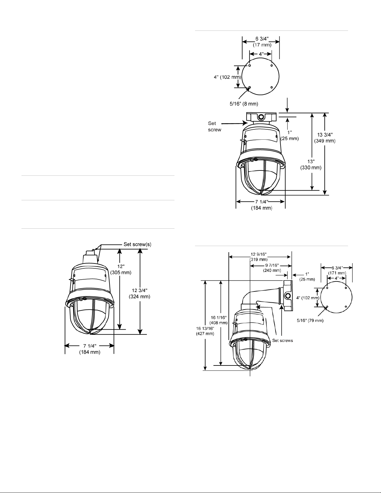
Figure 5 on page 3. See Table 3 on page 5 for
required supply wire temperature ratings. Install
main housing to the ceiling mount module. Tighten
the setscrew to secure the 116 main housing to the
ceiling mount module.
c. Bracket Mount Models (Figure 3 below): Install
the ceil
ing mount module, Cat. No. 116EX-C, using
hardware (not supplied) that is suitable for the
mounting surface. Install the wall mount module,
Cat. No. 116EX-B, to the 116 main housing.
Tighten the setscrew to secure wall mounting
module to the main housing. Run the unit's wiring
through the elbow to the wall box. Connect field
earth ground wire to ground screw or earth ground
via conduit system. Wire the unit in accordance
with Figure 5 on page 3. See T able 3 on page 5
for requir
ed supply wire temperature ratings. Install
the main housing and 116EX-B wall mount module
to the ceiling mount module. Tighten the setscrew
to secure the 116EX-B wall mount module to the
ceiling mount module.
WARNING: To reduce the risk of ignition of hazardous
atmospheres and shock, keep assembly tightly closed when
circuits are energized.
Figure 2: Detail of ceiling mounting
2. Apply power to the unit and ensure proper function.
Figure 1: Detail of pendant mounting
Figure 3: Detail of wall bracket mounting
2 / 6 P/N 3101131 • REV 04.00 • ISS 24JUN11
Page 3

Figure 4:
Figure 5: Wiring
Disassembly of the 116 Class fire alarm strobe
WARNING: To reduce the risk of ignition of hazardous
atmospheres and shock, keep assembly tightly closed when
circuits are energized.
ARNING: To reduce the risk of ignition of hazardous
W
atmospheres and shock, disconnect from the supply and
circuit and allow five (5) minutes for stored energy to
dissipate before disassembling the unit.
Legend
Strobe
Wire nut
Notes
• DC polarity of circuit shown in supervisory state (signal inactive). Reverse circuit polarity to activate signal.
• Electrical supervision requires wire run to be broken at each device.
• Device for constant input voltage. Do not connect to “coded” or pulsating voltage.
• For non-fire alarm use, i.e., without field wire supervision, the installer can tie the two white leads together and tie the two black leads
together.
Figure 6: Mounting options
P/N 3101131 • REV 04.00 • ISS24JUN11 3 / 6
Page 4
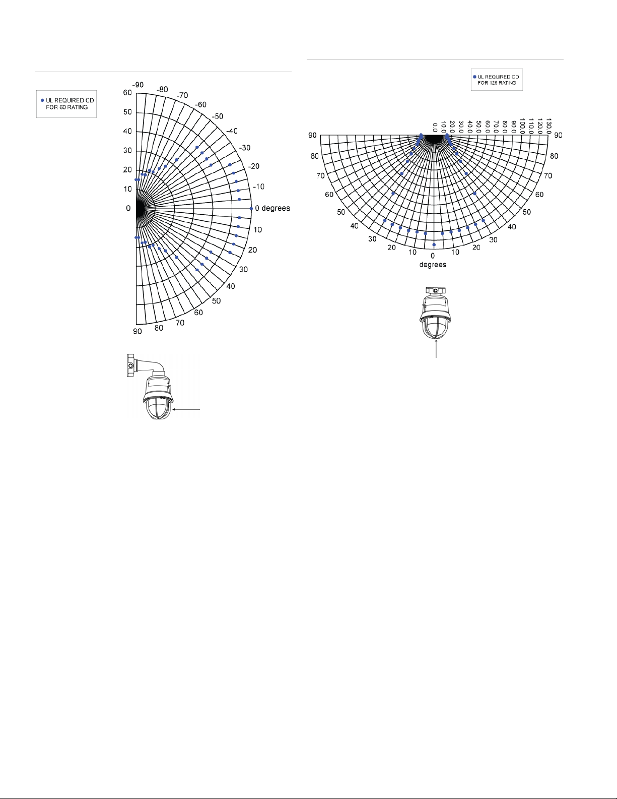
Figure
7: Effective candela light output for wall bracket mount,
vertical plane (zero degree angle at side of globe)
Figure
8: Effective candela light output for ceiling mount, X & Y
planes (zero degree angle at bottom of globe)
Notes
• Optional dome guard shown, candela output readings taken
without optional dome guard installed.
• Refer to “Specifications” on page 5 for candela ratings
Notes
• Optional dome guard shown, candela output readings taken
without optional doe guard installed.
• Refer to “Specifications” on page 5 for candela ratings
4 / 6 P/N 3101131 • REV 04.00 • ISS 24JUN11
Page 5
Specifications
Voltage 16 - 33 VDC / FWR
Max RMS operating
current*
Candela rating (without
guard)
Wall
Ceiling
Candela rating (with
guard)
Wall
Ceiling
Caution: To prevent damage to the signal circuit and to
otherwise assure continued proper functioning, DO NOT
operate the unit outside of the regulated 24 VDC/FWR voltage
range of 16 – 33 VDC/V FWR.
*The Max RMS operating current is defined as the current rating over
the entire voltage range.
**The designation “Regulated 24” refers to the voltage range of 16 –
33 volts
Table 1: Compatible synchronization modules
Model names Model numbers
Auto-sync output module SIGA-CC1S
0.505 A at 24 VDC Regulated**
0.683 A at 24 VDC FWR
60 cd
125 cd
51 cd
86 cd
SIGA-CC1S-LG
SIGA-MCC1S
SIGA-MCC1S-LG
Model names Model numbers
Genesis signal master – remote
mount
Table 2: 116 Class catalog numbers
Description Catalog number Housing color
Housing less mounting
module
Ceiling mount module –
3/4” NPT
Pendant mount module –
3/4” NPT
Wall mount module (requires
use of ceiling mount module)
ADTG1M-RM
EG1M-RM
G1M-RM
G1M-RM-LG
MG1M-RM
XLSG1M-RM
ZG1M-RM
116DEGEX-FJ
116DEGEX-FJ-R
116EX-C
116EXR-C
116EX-P
116EXR-P
116EX-B
116EXR-B
Gray
Red
Gray
Red
Gray
Red
Gray
Red
Table 3: Ratings
Ambient temp. Supply wire temp.
marking
40°C 75°C T2B (260°C) T6 (85°C) T4A (120°C) T4A (120°C)
55°C 90°C T2B (260°C) T6 (85°C) T4 (135°C) T4 (135°C)
65°C 105°C T2B (260°C) T6 (85°C) T3C (160°C) T3C (160°C)
Class I, Div. 2
Groups A, B
Class I, Div. 1 & 2
Groups C, D
Class II & III, Div. 1
Groups E, F, G
Class II & III, Div. 2
Groups F, G
P/N 3101131 • REV 04.00 • ISS24JUN11 5 / 6
Page 6

Regulatory information
Manufacturer Edwards, A Division of UTC Fire & Security
Ratings UL 1638 visual signaling – private mode
Americas Corporation, Inc.
8985 Town Center Parkway, Bradenton, FL
34202, USA
emergency and general utility signaling
UL 1971
UL and cUL listed as a Type 3R and Type 4X
enclosure
Contact information
For contact information, see www.edwardssignaling.com.
6 / 6 P/N 3101131 • REV 04.00 • ISS 24JUN11
 Loading...