

Page 1
VISUAL SIGNALS
FEATURES
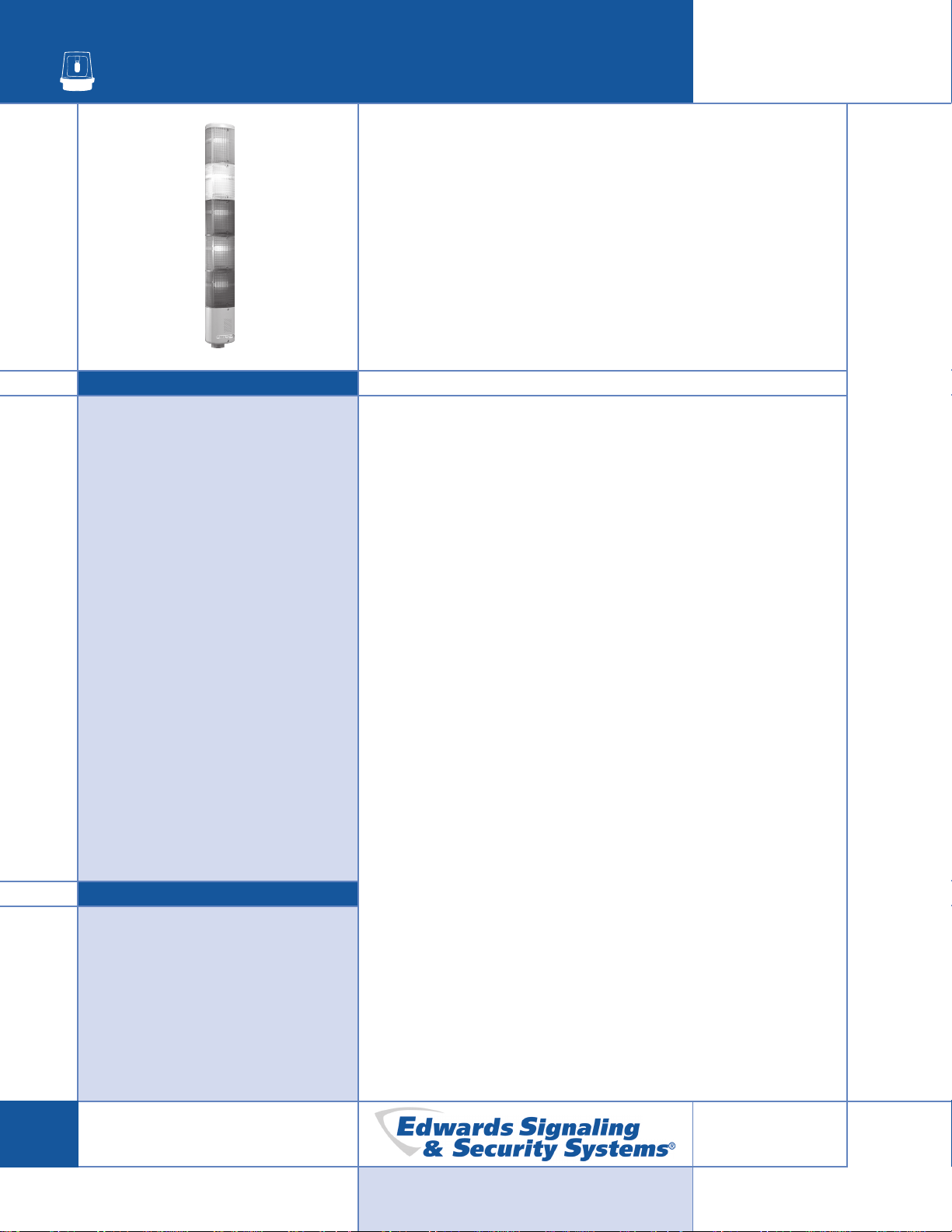
Triliptical® Stackable
Status Indicator
DeviceNetTM, PLC Compatible
102 Series
> PLC compatible
> Seven interchangeable light
source modules:
steady-on or flashing
incandescent
steady-on or flashing halogen
steady-on or flashing LED
300,000 peak candela strobe
> Molded-in gasketed lens modules
> Six lens colors available: red,
amber/orange, yellow, blue, green
& clear
> Stackable in any combination or
color
> Base unit comes with optional
tone module
> Module rearrangement requires
no wiring
AGENCY APPROV
> UL 1638 Listed
> CE Marked low voltage directive
and EMC directive
> NEMA Type 3R, Type 4X and IP65
Rated
ALS
The Edwards Triliptical Stackable Status Indicator is a unique
audible-visual signaling device that can contain up to 5 light
modules and a pulsating horn in a single “stack.” All modules are
gasketed.
The Triliptical Stackable Status Indicator bases are availab le in
three models. A shorter base for conduit or surface mounting or a
larger base designed for use with an optional tone module
assembly. The larger base is also av ailable with an optional
DeviceNet interface.
The Triliptical diffusion optic lens allows viewing from close up while
still projecting the light through use of a built-in projection ring. The
lenses are available in six colors: red, amber/orange, yellow, b lue,
green, and clear. Each light source module contains a remo vable
cover to allo w for easy relamping. The light module cover features a
molded-in gasket for dust tight reliability. Double optics and the
triliptical design provides an increased viewing area without
increasing the base diameter. The lens modules can be easily
stacked together utilizing an internal retaining assembly . Two tone
modules are available. A single tone module and a tone selectable
tone module - one tone selectable from eight available tones.
Provides up to 85 dB at 5 feet. The multi-tone module is also
available with an optional DeviceNet interface that allows all eight
tones to be controlled over a DeviceNet network.
Surface or 3/4" (19mm) NPT conduit pipe mounting in nonhazardous dust and weatherproof applications. It is recommended
that the unit be mounted vertically with lenses facing up.
> cUL Listed
D-04
3-62
© Copyright 2004 Edwards
Page 2
TECHNICAL INFORMATION
VISUAL SIGNALS
DeviceNet Compatible Stackable Status
Indicator
The 102 Series Triliptical Stackable Status Indicator
has been tested by OD V A's authorized independent
test lab and complies with OD VA conformance test
software.
The Triliptical DeviceNet Stackable Beacon is a slav e
device. It is a general purpose status indicator
designed to indicate the status of a machine or
process. The unit contains a preprogrammed
microcontroller which implements the Group 2
predefined Master/Slave Connection Set. This allows
for one Explicit Messaging Connection and one P oll
Connection. The Stackab le Beacon resets
automatically when DeviceNet power is applied.
The DeviceNet interface is in the Triliptical DeviceNet
Base, 102TBS-DN, which interfaces between the
DeviceNet network and all installed stacklight
modules. The unisolated ph ysical lay er contains
DeviceNet required mis-wiring protection circuitry . A
standard open style (unsealed) 5 pin connector is
used to connect the Stackable Beacon to the
DeviceNet bus. The current draw from the bus is
0.12A. The pow er required to drive the lamps is
supplied separately from the bus power for the 120V
AC (N5) version. DC power for the 24V DC (G1)
version may be taken locally or from the DeviceNet
Network. A standard open style 2 pin connector is
used to connect 24V DC @ 1.6A or 120V AC at 0.6A
to drive the 5 light sources.
The DeviceNet compatible unit provides for complete
light source diagnostics. Each light source: LED,
strobe, halogen or incandescent is continuously
monitored for operability . An inoperab le or missing
light source is reported on the DeviceNet network.
SIGNAL INPUT LOAD CHARACTERISTICS*
Light Source/Tone Module Operating Max. off state Continuous on Surge (inrush/duration)
Cat. No. Voltage leakage current (mA) Current (mA) Amps/milliseconds
102SIGST-G1 24V DC 5 50 .24/.2
102SIGST-N5 120V AC 5 70 .35/.5
102SIGMT-G1 24V DC 5 50 .24/.2
102SIGMT-N5 120V AC 5 70 .35/.5
102LS-SIN-G1 24V DC 25 32 .36/1
102LS-SIN-N5 120V AC 25 80 .15/8
102LS-SINH-G1 24V DC 25 320 .36/1
102LS-SINH-N5 120V AC 25 110 .5/8
102LS-FIN-G1 24V DC 25 32 1.4/100
102LS-FIN-N5 120V AC 25 80 .3/8
102LS-FINH-G1 24V DC 25 320 1.2/100
102LS-FINH-N5 120V AC 25 110 1.15/8
102LS-ST-G1 24V DC 1.5 300 .33/1
102LS-ST-N5 120V AC 5 120 50/1
102LS-SLED( )-G1 24V DC 5 65 .025/1
102LS-SLED( )-N5 120V AC 5 25 .09/8
102LS-FLED( )-G1 24V DC 5 65 .07/1
102LS-FLED( )-N5 120V AC 5 25 .09/8
*This device is PLC compatible and may be operated by PLCs with output characteristics that match the input load requirements of this signal.
102 Series continued on next page
© Copyright 2004 Edwards
D-04
3-63
Page 3

VISUAL SIGNALS
3"
Part # 023001 Cap
(supplied with
base module)
Signal Base
(Cat. No.
102TBS)
Part # 023001 Cap
3"
(supplied with
base module)
Signal Base
(Cat. No.
102PMBS)
125/8"
(321mm)
(32mm)
1
/4"
1
1
/2"
(13mm)
5
/8"
3
(92mm)
(76mm)
121/8"
(308mm)
(44mm)
3
/4"
1
1
/2"
(13mm)
5
/8"
3
(92mm)
(76mm)
Electrical Lamp Replacement Lamp Life (hours) Manufacturer's
+
N/A N/A N/A N/A N/A
+
+
N/A N/A N/A N/A N/A
+
+
N/A N/A N/A N/A N/A
+
3"
##
Part # 023001 Cap
(supplied with
base module)
Signal Base
(Cat. No.
102DMBS)
Gasket
Light Output
TECHNICAL INFORMATION
151/2"
(394mm)
1
/2"
(13mm)
5
3
/8"
(92mm)
1
4
/8"
(105mm)
(76)mm
Catalog No. Description Ratings Ratings Lamp Calculated#Projected
102TBS-G1 Base Unit - Use with 24V DC, 1.75A
102TBS-N5 optional horn assy 120V AC, 0.60A
102DMBS-G1 Mini base for 24V DC, 1.75A
102DMBS-N5 direct panel mount 120V AC, 0.60A
102PMBS-G1 Mini base for 3/4" 24V DC, 1.75A
102PMBS-N5 (19mm) conduit mt 120V AC, 0.60A
102SIGST-G1 Optional Tone 24V DC, 0.05A N/A N/A N/A N/A N/A
102SIGST-N5 Module 120V AC, 0.05A
102SIGMT-G1 24V DC, 0.05A N/A N/A N/A N/A N/A
102SIGMT-N5 120V AC, 0.05A
102PMF Pipe Mount Flange N/A N/A N/A N/A N/A N/A
102MP-4 (4") Pipe Extensions (for use N/A N/A N/A N/A N/A N/A
102MP-10 (10") with Pipe Mount Flange) N/A N/A N/A N/A N/A N/A
102MP-15 (15") N/A N/A N/A N/A N/A N/A
102LM-* Lens Module N/A N/A N/A N/A N/A N/A
102LS-SINH-G1 Steady-on Halogen 24V DC, 0.32A 9 Watts 50LMP-9WH 12,000 — 653 peak candela
102LS-SINH-N5 Light Source 120V AC, 0.11A 12 Watts 50L MP-12WH 20,000 — 879 peak candela
102LS-SIN-G1 Steady-on Incandescent 24V DC, 0.32A 10 Watts Ind. Trade 303 10,000 — 829 peak candela
102LS-SIN-N5 Light Source 120V AC, 0.08A 10 Watts 50LMP-10W 2,500 — 829 peak candela
102LS-FINH-G1 Flashing Halogen 24V DC, 0.32A 9 Watts 50LMP-9WH 12,000 15,000 653 peak candela
102LS-FINH-N5 Light Source 120V AC, 0.11A 12 Watts 50LMP-12WH 2 0, 000 25,000 879 peak candela
102LS-FIN-G1 Flashing Incandescent 24V DC, 0.32A 10 Watts Ind. Trade 303 10,000 12,500 829 peak candela
102LS-FIN-N5 Light Source 120V AC, 0.08A 10 Watts 50LMP-10W 2,500 3,000 829 peak candela
102LS-ST-G1 Strobe 24V DC, 0.30A 3 Joule N/A 3,000
102LS-ST-N5 Light Source 120V AC, 0.12A 3 Joule N/A 3,000
102LS-SLEDA-G1** Steady-on LED 24V DC — N/A 120,000 — 4346 peak candela
102LS-SLED(
++
)-G1** Light Source 0.062A 1821 peak candela
###
###
— 300,000 peak candela
— 300,000 peak candela
102LS-SLEDA-N5** 120V AC — N/A 120,000 — 4346 peak candela
102LS-SLED(++)-N5** 0.022A 1821 peak candela
102LS-FLEDA-G1** Flashing LED 24V DC — N/A 120,000 — 4346 peak candela
102LS-FLED(
++
)-G1** Light Source 0.062A 1821 peak candela
102LS-FLEDA-N5** 120V AC — N/A 120,000 — 4346 peak candela
102LS-FLED(
102TBS-DN-G1 DeviceNet Base Unit 24V DC, 1.75A
102TBS-DN-N5 120V AC, 0.60A
++
)-N5** 0.022A 1821 peak candela
+
N/A N/A N/A N/A N/A
+
102SIGMT-DN-G1 DeviceNet Base Mounted 24V DC, 0.05A N/A N/A N/A N/A N/A
102SIGMT-DN-N5 Optional Tone Module 120V AC, 0.05A
+
Currents shown are for a stackable with 5 light modules. ++Signifies lens and LED color (B - blue, G - green, R - red or W - white)
*Signifies lens module color (A - amber/orange, B - blue, C - clear, G - green, R - red, Y - yellow)
**
NOTE: LED light sources must be used with the corresponding color lens module (e.g., a blue LED light source, 102LS-SLEDB-G1, must be used with a blue lens, 102LM-B).
#
D-04
At nominal operating voltage. ##Projected lamp life based on manufacturer's calculated lamp life @ 65 fpm and 50% duty cycle.
###
Strobe tube life @ operating power to 75% efficiency.
3-64
© Copyright 2004 Edwards
Page 4

VISUAL SIGNALS
TECHNICAL INFORMATION
How-to-order Triliptical Stacklites
To build a Stacklite, one base unit and the required number of lens modules and light sources need to be
ordered. F or e xample , to build a 120VAC, two high, steady incandescent stacklight on a direct mount base ,
order (one) 102DMBS-N5, (two) 102LM (in required colors), and (two) 102LS-SIN-N5.
Base
Unit
Tone
Module
Lens
Modules
Light
Sources
102 + — —
○○○○○○○○
Cat. No.
TBS = Use with optional tone module. Wiring
102
102 + —
102
102 + —
Cat. No.
102
102 +
Cat. No.
102
DMBS = Mini base for direct panel mount*
PMBS = Mini base for 3/4" (19mm) conduit mount*
*Cap i nclu ded ** DN = Optional DeviceNet
○○○○○○○○
SIGST = Optional Single-Tone Module
SIGMT= Optional Multi-Tone Module
○○○○○○○○
○○○○○○○○
terminals 3/4" (19mm) conduit mount*
LM
○○○○○○○○
Options
LM = Lens module
LS
○○○○○○○○
Light
SINH = Steady-on halogen
FINH = Flashing halogen
LS =
Light
Source
SIN = Steady-on standard
FIN = Flashing standard
ST = Strobe
SLED = Steady-on LED
FLED = Flashing LED
○○○○○○○○
Options
○○○○○○○○
A = Amber/orange B = Blue C = Clear
G = Green R = Red Y = Yellow
○○○○○○○○
Type
incandescent
incandescent
Lens Color
(LED Only)
A = Amber
B = Blue
G = Green
R = Red
W= White
○○○○○○○○
DN**
○○○○○○○○
DN**
○○○○○○○○
○○○○○○○○
Color
Voltage
G1 = 24V DC
N5 = 120V AC
—
G1 = 24V DC
N5 = 120V AC
G1 = 24V DC
—
Voltage
G1 = 24V DC
N5 = 120V AC
○○○○○○○○
○○○○○○○○
○○○○○○○○
Pre-Assembled Three High
Steady-On Incandescent Models
The Triliptical Stackable Beacon is available pre-assemb led 3 high stacks as sho wn in the below tab le.
Catalog No. Voltage Colors Light Source Type
102SIN-RGA-G1 24V DC Red, Green, Amber/Orange Steady-On Incandescent
102SIN-RBA-G1 24V DC Red,
102SIN-RGA-N5 120V AC Red, Green, Amber/Orange Steady-On Incandescent
102SIN-RBA-N5 120V AC Red, Blue, Amber/Orange Steady-On Incandescent
© Copyright 2004 Edwards
Blue, Amber/Orange Steady-On Incandescent
D-04
3-65
 Loading...