

Page 1
Instruction Manual
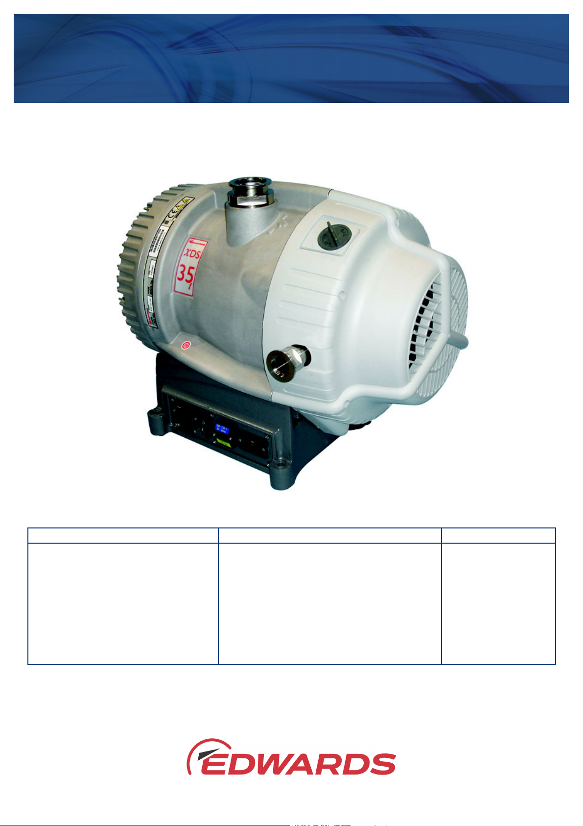
XDS35i, XDS35iC, XDS35iE and XDS35iCE Scroll Pumps
A730-01-880
Issue L
Description Electrical Supply Item Number
XDS35i Scroll Pump (set to high volts} 100-120 V, 200-230 V, 50/60 Hz - Set to 200 - 230 V A730-YY-983
XDS35i Scroll Pump (set to low volts) 100-120 V, 200-230 V, 50/60 Hz - Set to 100 - 120 V A730-YY-986
XDS35i Scroll Pump 100-120 V, 200-230 V, 50/60 Hz - Set to 200 - 230 V A730-01-983
XDS35iC Scroll Pump Chemical 100-120 V, 200-230 V, 50/60 Hz - Set to 200 - 230 V A730-06-938
XDS35i Scroll Pump (No Gas Ballast) 100-120 V, 200-230 V, 50/60 Hz - Set to 200 - 230 V A730-05-983
XDS35iE Scroll Pump Enhanced 100-120 V, 200-230 V, 50/60 Hz - Set to 200 - 230 V A730-03-983
XDS35iCE Scroll Pump Enhanced Chemical 100-120 V, 200-230 V, 50/60 Hz - Set to 200 - 230 V A730-08-983
XDS35iE Scroll Pump Enhanced (No Gas Ballast) 100-120 V, 200-230 V, 50/60 Hz - Set to 200 - 230 V A730-07-983
Original Instructions
Page 2

This product has been manufactured under a quality management system certified to ISO 9001:2015.
P200-01-400-M
2006/42/EC
Machinery directive
2014/35/EU
Low voltage directive
2014/30/EU
Electromagnetic compatibility (EMC) directive
2014/34/EU
ATEX directive on use in potentially explosive atmospheres
II 3 G Ex h IIB T4 Gc Internal Atmospheres Only, Tech File ref 209
2011/65/EU
Restriction of certain hazardous substances (RoHS) directive
EN 1012-2:1996
+A1:2009
Compressors and vacuum pumps. Safety requirements. Vacuum pumps
EN 13463-1:2009
Non-electrical equipment for use in potentially explosive atmospheres. Basic method
requirements
EN 13463-5:2011
Non-electrical equipment for use in potentially explosive atmospheres. Protection
by constructional safety ‘c’
EN 61010-1:2010
Safety requirements for electrical equipment for measurement, control and
laboratory use. General requirements
EN 61326-1:2013
Electrical equipment for measurement, control and laboratory use. EMC
Class A Emissions, Industrial Immunity
CSA-C22.2
No.61010-1-12
Safety requirements for electrical equipment for measurement, control and
laboratory use –Part 1: General requirements
L61010-1
3rd Edition
Safety requirements for electrical equipment for measurement, control and
laboratory use – Part 1: General requirements
Mr Ian Keech
Date and Place
Declaration of Conformity
Edwards Ltd,
Innovation Drive,
Burgess Hill,
West Sussex, RH15 9TW, UK
The following products:
XDS35i scroll pump, 100-120 V, 200-230 V, 1 ph, 50/60 Hz, set to high volts A730-YY-983
XDS35i scroll pump, 100-120 V, 200-230 V, 1 ph, 50/60 Hz, set to low volts A730-YY-986
XDS35i scroll pump, 100-120 V, 200-230 V, 1 ph, 50/60 Hz A730-01-983
XDS35i scroll pump no gas ballast, 100-120 V, 200-230 V, 1 ph, 50/60 Hz A730-05-983
XDS35iC scroll pump, 100-120 V, 200-230 V, 1 ph, 50/60 Hz A730-06-983
XDS35iE scroll pump enhanced, 100-120 V, 200-230 V, 1 ph, 50/60 Hz A730-03-983
XDS35iE scroll pump no gas ballast enhanced, 100-120 V, 200-230 V, 1 ph, 50/60 Hz A730-07-983
XDS35iCE scroll pump enhanced, 100-120 V, 200-230 V, 1 ph, 50/60 Hz A730-08-983
XDS46i scroll pump, 100-120 V, 200-230 V, 50/60 Hz, single phase A731-01-983
XDS46iC scroll pump, 100-120 V, 200-230 V, 50/60 Hz, single phase A731-06-983
XDS100B scroll pump, 100-120V, 200-230V, 50/60Hz, single phase A732-01-983
where YY is represented by a two digit number between 01 and 99.
Is in conformity with the relevant requirements of European CE legislation:
Based on the relevant requirements of harmonised standards:
requirements. General requirements
The product also complies with the following:
This covers all product serial numbers from the date of this declaration onwards.
22.10.2018, Burgess Hill
Vice President Engineering, High Vacuum Division
This declaration is based on the requirements of EN ISO 17050-1 and the relevant directives.
Page 3
P200-10-019
Issue D
Material Declaration
In accordance with the requirements of the Chinese regulatory requirement on the Ma nagement Methods for the
Restriction of the Use of Hazardous Substances in Electrical and Electronic Products Order No. 32 (also known as
‘China RoHS2’) and SJ/T 11364 Marking for the Restricted Use of Hazardous Substances in Electronic and Electrical
Products:
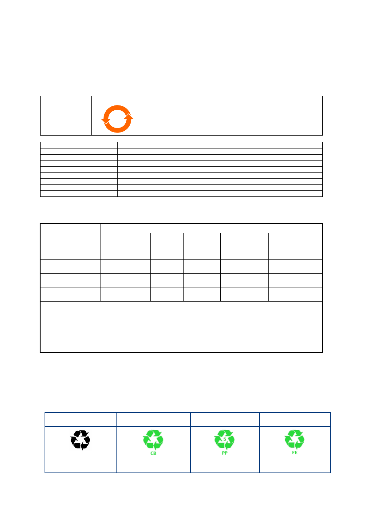
Product Labels
Product Product Label Meaning
This product contains hazardous substances in at least one of the
All pumps in the
list below
Pump Type Pump Size
RV Pumps RV3,5,8,12, E Lab, nRVi
EM Small Pumps E2M0.7, 1.5, E1M18, E2M18, 28, 30, nE2M40i
nEXT Pumps nEXT 85, 240, 300, 400, Splitflow
nXDS pumps nXDS 6, 10, 15, 20
EXT pumps EXT75DX
XDS pumps XDS35, 46, 100
Diaphragm XDD 1, D lab
Turbo Pump Carts T station, nEXPT, nEXT station
部件名称
Part name
铸铝
Cast Aluminium
铜管管件
Brass pipe Fittings
铜接头
Brass Connectors
2020
铅
Lead
(Pb)
Mercury
X O O O O O
X O O O O O
X O O O O O
homogeneous materials used which are above the limit requirement
in GB/T 26572 as detailed in the declaration table below.
These parts can safely be used for the environmental protection use
period as indicated.
材料成分声明
Materials Content Declaration
质
汞
(Hg)
镉
Cadmium
(Cd)
危险物
六价铬
Hexavalent
Chromium
(Cr VI)
多溴联苯
Polybrominated
biphenyls (PBB)
Polybrominated
diphenyl ethers
多溴二苯醚
(PBDE)
O: 表示该有害物质在该部件的所有均质材料中的含量低于 GB/T 26572 标准规定的限量要求。
O: Indicates that the hazardous substance contained in all of the homogeneous materials for this part is below
the limit requirement in GB/T 26572.
X: 表示该有害物质在该部件的至少一种均质材料中的含量超出 GB/T26572 标准规定的限量要求。
X: Indicates that the hazardous substance contained in at least one of the homogeneous materials used for
this part is above the limit requirement of GB/T26572.
NOTES: These products are EU RoHS compliant, the following Exemptions apply:
6(b) Lead as an alloying element in aluminium containing up to 0.4% by weight.
6(c) Copper alloy containing up to 4% lead by weight
Packaging Information
Pallet Over-shipper Protection Pieces Support Braces
NWNW
Recyclable Natural Wood Recyclable Cardboard Recyclable Polypropylene Recyclable Mild Steel
Page 4

This page has been intentionally left blank.
Page 5

A730-01-880 Issue L
Contents
Section Page
1 Introduction ....................................................................................... 1
1.1 Scope of this manual .................................................................................................... 1
1.2 ATEX directive implication ............................................................................................. 2
1.3 Description ................................................................................................................ 3
1.4 Gas ballast control ....................................................................................................... 4
1.5 Construction .............................................................................................................. 4
2 Technical data .................................................................................... 5
2.1 Operating and storage conditions ..................................................................................... 5
2.2 Performance .............................................................................................................. 5
2.2.1 General .................................................................................................................... 5
2.2.2 Performance characteristics ........................................................................................... 6
2.3 Mechanical data .......................................................................................................... 7
2.3.1 General .................................................................................................................... 7
2.4 Electrical data ............................................................................................................ 7
2.4.1 Electrical cables .........................................................................................................8
Contents
3 Installation ......................................................................................... 9
3.1 Safety ......................................................................................................................9
3.2 System design considerations ......................................................................................... 10
3.3 Unpack and inspect ..................................................................................................... 12
3.4 Locate the pump ........................................................................................................12
3.4.1 Mechanical fixing .......................................................................................................12
3.5 Electrical installation ..................................................................................................12
3.5.1 Check and configure the pump .......................................................................................12
3.5.2 Connect the pump to the electrical supply ......................................................................... 13
3.6 Inlet and outlet connections ..........................................................................................13
3.7 Leak test the system ...................................................................................................14
4 Operation ........................................................................................ 15
4.1 Use of gas ballast control (if fitted) .................................................................................15
4.1.1 Gas ballast control ...................................................................................................... 15
4.2 Start up procedure ..................................................................................................... 15
4.3 To achieve ultimate vacuum (if gas ballast fitted) ................................................................ 16
4.4 To pump condensable vapours (if gas ballast fitted) ..............................................................16
4.5 Implication of ATEX directive ......................................................................................... 16
4.5.1 Flammable/pyrophoric materials ....................................................................................16
4.5.2 Gas purges ...............................................................................................................16
4.6 Remote operation using 15-way D connector ...................................................................... 17
4.7 Shut down ................................................................................................................17
5 Maintenance ..................................................................................... 19
5.1 Safety information ...................................................................................................... 19
5.2 Maintenance plan .......................................................................................................20
5.3 Inspect and clean the inlet strainer ................................................................................. 20
5.4 Inspect and clean the gas ballast control (if fitted) ............................................................... 21
5.5 Clean the external fan cover ......................................................................................... 22
5.6 Replace the tip seals ...................................................................................................22
5.7 Test the motor condition ..............................................................................................23
5.8 Fault finding .............................................................................................................23
cg/8299/10/18
© Edwards Limited 2018. All rights reserved. Page i
Page 6

A730-01-880 Issue L
Contents
5.8.1 The pump has failed to start or has stopped .......................................................................23
5.8.2 The pump has failed to achieve the required performance ...................................................... 23
5.8.3 The pump is noisy ....................................................................................................... 24
5.8.4 The pump surface temperature is high .............................................................................. 24
5.8.5 The pumping speed is poor or if pump down time is too long ...................................................24
6 Storage and disposal ........................................................................... 25
6.1 Storage ...................................................................................................................25
6.2 Disposal ...................................................................................................................25
7 Service and spares .............................................................................. 27
7.1 Introduction .............................................................................................................27
7.2 Service ....................................................................................................................27
7.3 Accessories ...............................................................................................................27
7.3.1 Electrical cables ........................................................................................................ 27
7.3.2 Silencer ................................................................................................................... 27
7.3.3 Gas ballast adaptor ..................................................................................................... 27
7.3.4 Solenoid operated pipeline valves ...................................................................................28
7.3.5 Service kits ..............................................................................................................28
Illustrations
Figure Page
1 General view ............................................................................................................. 3
2 Performance characteristics of XDS35i ............................................................................... 6
3 Performance characteristics of XDS35iE ............................................................................. 6
4 Installation drawing (dimensions in mm) ............................................................................11
5 Logic interface schematic .............................................................................................18
6 Inlet strainer assembly ................................................................................................. 21
7 Gas ballast control assembly ..........................................................................................22
Page ii © Edwards Limited 2018. All rights reserved.
Page 7

A730-01-880 Issue L
Tables
Table Page
1 Operating and storage conditions ..................................................................................... 5
2 General characteristics ................................................................................................. 5
3 Performance characteristics ........................................................................................... 6
5 General mechanical data ............................................................................................... 7
6 Electrical data ............................................................................................................ 7
7 Recommended regional supply protection ........................................................................... 7
8 Recommended cordsets ................................................................................................. 8
9 Pin status on the logic interface connector ........................................................................18
10 Maintenance plan .......................................................................................................20
11 Solenoid operated pipeline valves ...................................................................................28
Associated publications
Publication title Publication number
Contents
Vacuum Pump and Vacuum System Safety P400-40-100
Tip Seal Replacement Kit Manual A730-01-840
By-pass Valves Exchange Manual A730-01-860
Trademark credits
Edwards and the Edwards logo are trademarks of Edwards Limited, Innovation Drive, Burgess Hill, West Sussex,
RH15 9TW, UK.
© Edwards Limited 2018. All rights reserved. Page iii
Page 8

A730-01-880 Issue L
This page has been intentionally left blank.
Page iv © Edwards Limited 2018. All rights reserved.
Page 9
A730-01-880 Issue L
CAUTION
WARNING
1Introduction
1.1 Scope of this manual
This manual provides installation, operation and maintenance instructions for the Edwards XDS35i, XDS35iC, XDS35iE,
and XDS35iCE scroll pumps. The pump must be used as specified in this manual. Read this manual before installing
and operating the pump.
Important safety information is highlighted as WARNING and CAUTION instructions; these instructions must be
obeyed. The use of WARNINGS and CAUTIONS is defined below.
Warnings are given where failure to observe the instruction could result in injury or death to
people. The actual symbol shown varies according to the hazard.
Cautions are given where failure to observe the instruction could result in damage to the equipment, associated
equipment and/or process.
Introduction
The units used throughout this manual conform to the SI international system of units of measurement.
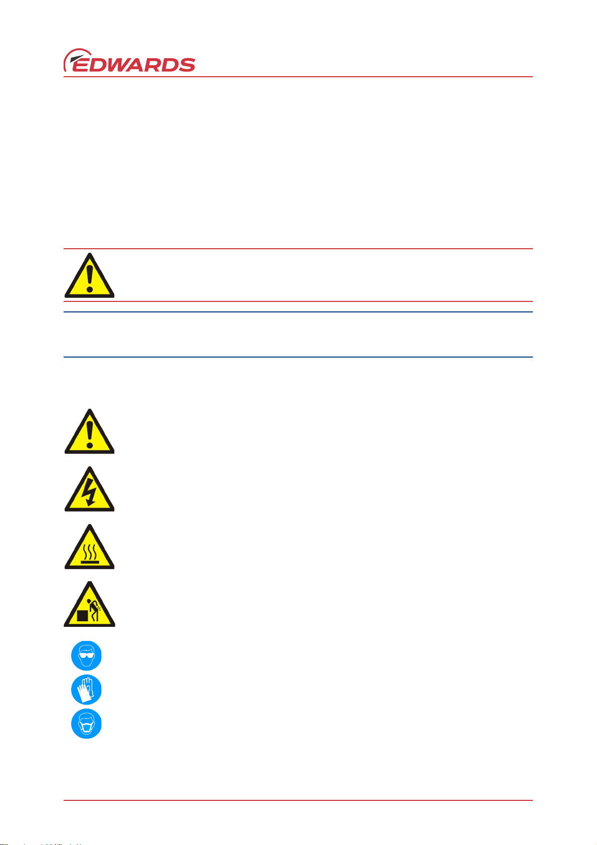
The following Warning labels may be present on the pump and used throughout the product documentation:
Warning/Caution – An appropriate safety instruction should be followed or a caution to a potential
hazard exists.
Warning – Dangerous Voltage. Indicates hazards arising from dangerous voltages.
Warning – Hot Surfaces. To indicate that the marked item can be hot and should not be touched without
taking precautions.
Warning – Heavy Object. Indicates the potential risk of physical injury and requires suitable lifting
equipment to move.
Warning - Use protective equipment. Indicates that appropriate protective equipment
must be used.
© Edwards Limited 2018. All rights reserved. Page 1
Page 10

A730-01-880 Issue L
Introduction
1.2 ATEX directive implication
This equipment is designed to meet the requirements of Group II Category 3 equipment in accordance with Directive
2014/34/EU of the European Parliament and the Council of 29th March 2014 on the approximation of the laws of the
Member States concerning equipment and protective systems intended for use in potentially explosive atmospheres.
(The ATEX Directive)
The ATEX Category 3 applies in respect of potential ignition sources internal to the equipment. An ATEX Category has
not been assigned in respect of potential ignition sources on the outside of the equipment as the equipment has not
been designed for use where there is an external potentially explosive atmosphere.
There is no potential source of ignition within the pump during normal operation but there may be potential sources
of ignition under conditions of foreseeable and rare malfunction as defined in the Directive. Accordingly, although
the pump is designed to pump flammable materials and mixtures, operating procedures should ensure that under all
normal and reasonably foreseeable conditions, these materials and mixtures are not within explosive limits.
Category 3 is considered appropriate for the avoidance of ignition in the case of a rare malfunction which allows
flammable materials or mixtures to pass through the pump whilst within their explosive limits.
Page 2 © Edwards Limited 2018. All rights reserved.
Page 11
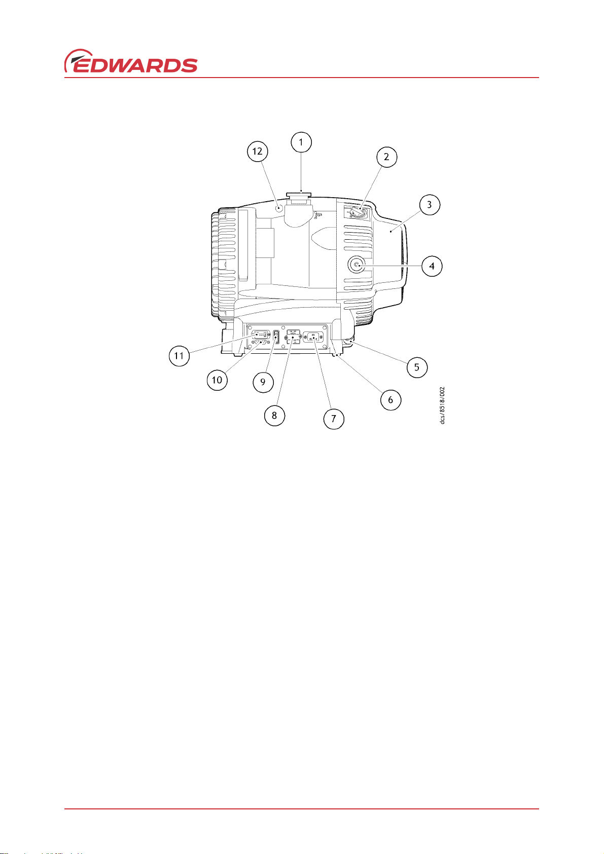
Figure 1 - General view
1. NW40 inlet port
2. Gas ballast control (not fitted on
No Gas Ballast variant)
3. Cooling fan
4. NW25 exhaust port
5. Fan connector
6. Rubber feet
7. Electrical connector
8. Voltage changeover switch cover
9. Run/Standby switch
10. 15-way connector
11. Hour counter
12. Lifting eye
A730-01-880 Issue L
Introduction
1.3 Description
Refer to Figure 1 for item numbers in brackets in the following descriptions.
The XDS pump is a compact, reliable vacuum pump which is suitable for use on vapour handling processes. It may be
used for some pumping applications involving corrosive substances and particulates; for information on pumping
flammable gases, please refer to Section 4.5 and contact Edwards for any further assistance.
The body of the pump includes a fixed scroll and an orbiting scroll. The orbiting scroll is controlled by the electric
motor through an eccentric cam on the motor drive shaft. The movement of the orbiting scroll, meshed with the
fixed scroll, forms successive crescent shaped volumes in the pump. Gas that enters the pump through the inlet is
compressed by the movement of the orbiting scroll and swept towards the centre of the fixed scroll. The compressed
gas enters the exhaust port near the centre of the stationary scroll and is exhausted from the pump through the
outlet.
The XDS is a dry vacuum pump, as all the bearings, with their hydrocarbon lubricant, are isolated from the vacuum
space.
The pump has an NW40 (item 1) inlet and inlet strainer.
© Edwards Limited 2018. All rights reserved. Page 3
Page 12

A730-01-880 Issue L
Introduction
The pump mechanism is driven directly by a three-phase electric motor. The motor is controlled by a drive, which
manages the supply of current to the motor in accordance with operating conditions and allows the pump to be
connected to a single phase supply. The voltage changeover switch beneath the voltage changeover switch cover
(item 8) must be set to the correct position in accordance with the power supply being used, refer to Section 3.5.2.
The pump is designed to run from atmospheric pressure however, if the inlet pressure exceeds 100 mbar for an
extended period, the inverter may reduce the motor speed. The pump will speed up again after the pressure is
reduced. Maximum rated continuous operating pressure at 40 °C ambient is 40 mbar.
The enhanced pump versions (XDS35iE and 35iCE) are equipped with patented technology which prevents overcompression within the scroll mechanism at high operational pressure and large throughput applications. Twin
by-pass valves release sufficiently compressed gas directly to the pump exhaust, increasing pump efficiency,
lowering power consumption and enhancing pumping speed. Valve operation occurs at inlet pressures greater than
300 mbar, meaning the pump is tailored towards applications which dwell at higher pressure. The elimination of overcompression at high operational pressure, reduces power consumption and diminishes bearing loads, extending
bearing life. Consequently, the enhanced versions are capable of operation without limitations to both the size of
vacuum chamber, or the frequency of pump down on cyclic duties.
Note: The pump modifications within the enhanced version have a small adverse effect on the ultimate vacuum
achieved however, the pump has a larger tolerance to operating altitude and ambient temperature.
The pump is air-cooled by a fan (item 3) mounted at the opposite end to the motor. The fan will continue to run for
one minute after the pump is switched off. The pump incorporates a thermal protection device that will stop the
motor in the event of thermal overload, for example, high ambient temperature. The pump will restart after cooling
down.
1.4 Gas ballast control
To pump high vapour loads, gas ballast can be delivered into the pump to prevent condensation of the vapour carried
by the pumped gases.
Air can be introduced to the low vacuum stages through the gas ballast control (item 2) (not fitted on the No Gas
Ballast variant). Alternatively, an inert gas such as nitrogen can be supplied through a suitable external valve and by
using the appropriate adaptor, available as an accessory, refer to Section 7.3.3.
The gas ballast control has three positions:
Closed (position '0')
Low flow (position 'I')
High flow (position 'II')
1.5 Construction
The pump scrolls are made of anodised aluminium. The motor housing is aluminium. All surfaces of the pump which
are exposed to the pumped gases are free from copper, zinc and cadmium.
Other materials of construction include fluorocarbon elastomer, nitrile, chemically resistant polymers, nickel,
stainless steel and a PTFE composite material.
Page 4 © Edwards Limited 2018. All rights reserved.
Page 13

A730-01-880 Issue L
WARNING
2Technical data
If the pump is operated outside the specific limits, the pump housing may become hot.
2.1 Operating and storage conditions
Table 1 - Operating and storage conditions
Ambient temperature range (operation) +10 °C to +40 °C
Maximum surface temperature of pump body under normal operating
conditions and maximum ambient temperature
Maximum humidity (operation) 90% RH
Ambient temperature range (storage) –30 °C to +70 °C
Pollution Pollution degree 2
Installation Installation category II
Altitude restriction UL/CSA approved maximum 2000 m
Area of use Indoor use
+40 °C to +65 °C
(3000 m for E variant
self certified)
Technical data
2.2 Performance
2.2.1 General
Tab l e 2 - G en eral c hara ct er is ti cs
3
Maximum pumping speed 35 m
Maximum permitted continuous inlet pressure 40 mbar
(1000 mbar for E variant)
Maximum permitted continuous exhaust pressure 0.2 barg
Maximum permitted gas ballast inlet pressure 0.5 barg
Maximum chamber volume to pump down from atmospheric pressure 100 litres
Maximum chamber volume for cyclic duty - maximum 6 cycles per hour 50 litres
Maximum initial pressure rise with no gas ballast flow 5 mbar l
Suck-back protection By exhaust valve
Leak tightness <1 x 10
Maximum displacement 44 m3/hr
Sound pressure, measured at ultimate vacuum 1 metre from the end of the
pump to ISO 3744 and ISO 4871
Vibration: measured at the inlet port (ISO 3744) Class 1C…< 4.5 mms
*
Use at higher inlet pressure speeds up the tip seal wear.
†
Enhanced version is not limited for maximum chamber volume or number of cycles per hour.
/h
-6
mbar l s
57 dB (A)
†
†
-1
–1
(rms)
*
© Edwards Limited 2018. All rights reserved. Page 5
Page 14

A730-01-880 Issue L
Technical data
2.2.2 Performance characteristics
The position of the gas ballast control defines the performance characteristics of the pump.
Note: Does not apply to No Gas Ballast variants.
Table 3 - Performance characteristics
Gas ballast
control position
0 <0.01 <0.03 –
1 <0.02 <0.04 3
2 <10.0 <10.0 12
Note: XDS35i can operate with high peak power for 90 seconds before activation of a thermal protection algorithm
which reduces rotational and pumping speed.
XDS35i Ultimate total
pressure (mbar)
Figure 2 - Performance characteristics of XDS35i
XDS35iE Ultimate total
pressure (mbar)
Gas ballast
flow (l min
–1
)
Figure 3 - Performance characteristics of XDS35iE
The power consumption of the enhanced version at high inlet pressure can be lowered by a further 100 W more with
the installation of a second exhaust silencer by an NW25 T-piece.
Page 6 © Edwards Limited 2018. All rights reserved.
Page 15

A730-01-880 Issue L
Table 4 - Typical pump down times of XDS35iE
3
Chamber size [m
114.5
343.3
10 144.3
30 432.7
The XDS35iE is suitable for regular, rapid pumping of small chambers or for evacuation of large volumes with no
maximum chamber limit.
]Pump down time [minutes]
2.3 Mechanical data
2.3.1 General
Technical data
Overall dimensions (L x W x H) 476 x 333 x 396 mm
Maximum tilt angle 10 degrees
Nominal rotational speed 1750 rpm
Mass 48 kg
Inlet connection NW40
Outlet connection NW25
Degree of protection (IEC60529) IP44
Table 5 - General mechanical data
2.4 Electrical data
Pumps are supplied set to 200 - 230 V
Table 6 - Electrical data
Supply (V) Phase Frequency (Hz) Current (A)
200 - 230 Single 50/60 6.6
100 - 120 Single 50/60 10.6
Table 7 - Recommended regional supply protection
Area Voltage Rating
UK 230 V 13 A
Europe 230 V 16 A
US 120 V 15 A
Japan 100 V 15 A
© Edwards Limited 2018. All rights reserved. Page 7
Page 16

A730-01-880 Issue L
Technical data
2.4.1 Electrical cables
Recommended cordsets and fuses for regional requirements.
Table 8 - Recommended cordsets
Description Rating Coupler type Item number
Cord set assembly, UK Cable Style = H05VV-F, 3 x 1.5 mm
70 °C, maximum length of 2.5 metres Straight entry A50505003
Plug Type = BS1363 UK plug
Appliance Coupler = IEC60320 style C19
Fuse Type = BS1362 13 Amp fuse, to an
IEC60320 style
Cord set assembly, Europe Cable Style = H05VV-F, 3 x 1.5 mm
70 °C, maximum length of 2.5 metres Straight entry A50506003
Plug Type = European Schuko VDE approved,
16 A 250 V rated with dual earthing contact
Appliance Coupler = IEC60320 style C19 Right angled entry A50506006
Cord set assembly,
USA/Canada (200 - 230 V)
Cable style = SJT, 3 x 14 AWG, 300 V, 90 °C,
VW-1 maximum length of 3 metres N/A
Plug Type = NEMA, 6-15P plug
Appliance Coupler = IEC 60320 style C19
2
, 300 V,
2
, 300 V,
Right angled entry A50505006
Page 8 © Edwards Limited 2018. All rights reserved.
Page 17

3 Installation
WARNING
WARNING
WARNING
WARNING
WARNING
3.1 Safety
Obey the safety instructions in this section and take note of appropriate precautions. Failure to
observe these instructions may result in injury to people and damage to equipment.
Do not expose any part of the human body to vacuum as it can cause injury.
The pump is not recommended for pumping explosive gases or hazardous substances.
A730-01-880 Issue L
Installation
Use suitable lifting equipment to move the pump. The mass is approximately 48 kg.
Take care when moving the pump into position. The pump's weight makes it difficult to slide and
movement should only be attempted by two people.
A suitably trained and supervised technician must install the pump.
Ensure that the installation technician is familiar with the safety procedures that relate to the products
processed by the pump.
Wear the appropriate safety clothing when coming into contact with contaminated components.
Dismantle and clean contaminated components inside a fume cupboard.
Vent and purge the vacuum system before starting installation work.
Disconnect other components in the pump from the electrical supply so that they cannot be operated
accidentally.
Refer to the Vacuum Pump and Vacuum System Safety manual (publication number P400-40-100) before
installing and using the pump to process hazardous or flammable materials.
Safely route any electrical cables and pipes to prevent a trip hazard.
Check all required components are available and are of the correct type before starting work.
Do not reuse O-rings or seals.
Leak test the system after installation is complete and seal any leaks found to prevent leakage of hazardous
substances out of the system and leakage of air into the system.
Mechanical lifting equipment should be attached to the lifting eye on the pump.
Loose slings should not be used to lift the pump.
© Edwards Limited 2018. All rights reserved. Page 9
Page 18

A730-01-880 Issue L
WARNING
Installation
3.2 System design considerations
Ensure the exhaust pipeline cannot become blocked. If an exhaust isolation valve is fitted, ensure
the pump cannot be operated with the valve closed.
Consider the following points when designing the pumping system:
Edwards recommend the use of a foreline vacuum isolation valve to allow the pump to warm up before pumping
condensible vapours or if the vacuum needs to be maintained when the pump is not running.
Avoid high levels of heat input into the pump from the process gases, otherwise the pump may overheat and cause
the thermal overload device to open.
If the pump is used in a high ambient temperature with high gas throughput, the pump body temperature may
approach 65 °C. Edwards recommends the use of additional guarding to prevent contact with hot surfaces under
these conditions.
Dilute flammable mixtures to safe concentrations by providing an inert gas dilution purge. Contact the Edwards
applications team for further advice on dilution requirements if required.
Page 10 © Edwards Limited 2018. All rights reserved.
Page 19

Figure 4 - Installation drawing (dimensions in mm)
A730-01-880 Issue L
Installation
© Edwards Limited 2018. All rights reserved. Page 11
Page 20

A730-01-880 Issue L
CAUTION
CAUTION
CAUTION
WARNING
WARNING
Installation
3.3 Unpack and inspect
Use suitable lifting equipment to move the pump. Mechanical equipment should be attached to the
lifting eyes; loose slings should not be used. Failure to do so can cause injury to people and damage
to the equipment. Refer to Table 5 for the mass of the pump.
Remove all packing materials, remove the pump from its packing box, remove the protective covers from the inlet
and outlet ports and inspect the pump.
If the pump is damaged, notify the supplier and carrier in writing within three days; state the Item Number of the
pump together with the order number and supplier's invoice number. Retain all packing materials for inspection. Do
not use the pump if it is damaged.
If the pump is not to be used immediately, replace the protective covers. Store the pump in suitable conditions, as
described in Section 6.1. Refer to Section 6.2 for disposal of materials.
3.4 Locate the pump
Route and secure cables, hoses and pipework during installation to avoid possible risk of trips.
If the pump will be located inside an enclosure, ensure there is adequate ventilation at both ends of the pump,
so that the ambient temperature of the pump does not exceed 40 °C. A minimum space of 25 mm between the
pump and the enclosure walls is required.
Provide a firm, level platform for the pump. Locate the pump so that the gas ballast control (if fitted) and the Run/
Standby switch is accessible.
3.4.1 Mechanical fixing
Use the four holes located on each corner of the pump base to secure the pump, if required. Edwards
recommends the use of M8 bolts.
3.5 Electrical installation
3.5.1 Check and configure the pump
Isolate the power supply before changing the voltage. Failure to configure the pump electrical supply correctly
can result in damage to the pump.
Ensure that the voltage shown on the voltage indicator (refer to Figure 1, item 8) on the motor cover corresponds
with the electrical supply voltage. If not, change the configuration of the pump motor to match the supply voltage
using the following procedure.
Page 12 © Edwards Limited 2018. All rights reserved.
Page 21

1. Undo the two screws and lift off the voltage indicator moulding.
WARNING
WARNING
WARNING
WARNING
WARNING
2. Rotate the voltage indicator moulding so that the correct voltage is uppermost.
3. Replace the two screws.
3.5.2 Connect the pump to the electrical supply
Ensure that the XDS pump electrical installation conforms to local and national safety
requirements. It must be connected to a suitably fused and protected electrical supply with a
suitable earth (ground) point.
For recommended regional supply protection and cordsets, refer to Section 2.4.
If using an earth leakage device, for example, an RCD, use a 30 mA rated unit at minimum to avoid
tripping during start up.
A730-01-880 Issue L
Installation
The pump will automatically restart after restoration of the power supply following power failure.
3.6 Inlet and outlet connections
If pumping dangerous gases or vapours, connect the exhaust to a suitable treatment plant to
prevent the discharge of dangerous gases and vapours to the surrounding atmosphere.
If pumping for a prolonged period above 100 mbar inlet pressure, use an exhaust silencer (refer
to Section 7.3.2) or connect to an appropriate exhaust line.
Before connecting the pump to the vacuum system, remove the plastic cap from the inlet and exhaust and ensure
the inlet strainer is fitted to the pump inlet port. Use appropriate NW40 vacuum fittings for connection to the system.
Take note of the following information when connecting the pump to the vacuum system.
To minimise noise and exhaust emissions, it is recommended that the pump is connected to an exhaust line
or a silencer (refer to Section 7.3.2).
For optimum pumping speeds, ensure that the pipeline connected to the pump inlet is as short as possible
and has a suitable internal diameter.
Support the vacuum pipeline to prevent loading of the coupling joints.
If the pump is operated with the exhaust line blocked, a pressure of 5.5 bar(a) may be generated in the
exhaust pipework. Connect the pump using appropriate pipework and fittings.
© Edwards Limited 2018. All rights reserved. Page 13
Page 22

A730-01-880 Issue L
Installation
If necessary, incorporate flexible bellows in the system pipelines to reduce the transmission of vibration and
prevent loading of the coupling joints. If using flexible bellows, ensure the use of bellows that have a
maximum pressure rating which is greater than the highest pressure that can be generated in the system.
The use Edwards bellows is recommended.
Incorporate an inlet isolation valve in the pipeline between the vacuum system and pump. This will isolate
the vacuum system from the pump when it is switched off and prevent the suck-back of process gases and
debris into the vacuum system.
Ensure that the sealing surfaces are clean and scratch-free.
Edwards recommends the use of an exhaust extraction system suitable for use with all process gases being pumped.
Ensure that the exhaust extraction system cannot become blocked or obstructed when the pump is operating.
A small amount of tip seal wear dust may collect in the exhaust duct of the pump. The dust may be blown out with
the initial burst of air after the pump has been vented. This is quite common and the amount of dust seen will reduce
over time.
3.7 Leak test the system
Leak test the system and seal any leaks found after installing the pump.
Page 14 © Edwards Limited 2018. All rights reserved.
Page 23

A730-01-880 Issue L
CAUTION
WARNING
4 Operation
4.1 Use of gas ballast control (if fitted)
The gas ballast control can be used to optimise the performance of the scroll pump for the application. The
performance characteristics of the pump with the different ballast settings are shown in Table 3. The position of the
gas ballast control can be changed when the pump is off or operating.
4.1.1 Gas ballast control
Use the gas ballast control to change the amount of air introduced into the final stage of the pump. Use of gas ballast
will reduce the condensation of vapours in the pump; the condensates would contaminate the pump. The gas ballast
control can be set to select one of three options:
To select no gas ballast, turn the control position to '0'. Use this setting:
to achieve ultimate vacuum
to pump dry gases.
To select low flow gas ballast, turn the control to position 'I'. Use this setting:
Operation
to pump low concentrations of condensable vapours
to decontaminate the pump.
To select high flow gas ballast, turn the control to position 'II'. Use this setting:
to pump high concentrations of condensable vapours
to clear excess vapours after processing.
High flow gas ballast ‘II’ is not intended for long term use as tip seal wear is accelerated. For continuous operation,
to dilute condensable vapours for example, gas ballast position ‘I’ is recommended.
4.2 Start up procedure
Ensure that the system design does not allow the exhaust pipeline to become blocked.
A fine dust may be emitted from the exhaust of the scroll pump during start up, particularly when the pump is
new or if new tip seals are fitted.
Use the procedure below to start up the pump:
1. Ensure that any vacuum system isolation valve is closed (if fitted).
2. Connect a suitable lead from the power supply to the appliance inlet at the side of the pump.
3. Switch on the electrical supply to the pump, using the Run/Standby switch Figure 1, item 9.
4. With manual operation always use the Run/Standby switch to start/stop the pump. If remote operation is used
to control the pump, refer to Section 4.6.
© Edwards Limited 2018. All rights reserved. Page 15
Page 24

A730-01-880 Issue L
WARNING
Operation
5. Open the vacuum system isolation valve (if fitted).
4.3 To achieve ultimate vacuum (if gas ballast fitted)
In order to achieve the best possible vacuum, the pump should be operated with the gas ballast control on position '0'.
However, if the pump, or elements of the vacuum system it is attached to, are new or have been newly fitted, some
atmospheric moisture may be present. If atmospheric moisture is present, run the pump with the gas ballast control
in position 'I' or 'II' for 20 minutes before switching to position '0'. If moisture is allowed to remain, the performance
of the pump will be impaired.
4.4 To pump condensable vapours (if gas ballast fitted)
Select a suitable gas ballast setting (gas ballast control in position 'I' or 'II') when there is a high proportion of
condensable vapours in the process gases. This will assist the vapours to pass through the pump without condensing
and keep the pump performance from degrading.
4.5 Implication of ATEX directive
4.5.1 Flammable/pyrophoric materials
When flammable or pyrophoric materials are present within the equipment:
Do not allow air to enter the equipment.
Ensure the system is leak tight.
Dilute any flammable gases or vapours by using an inert purge, for example nitrogen, to the pump inlet
and/or gas ballast (if fitted) to reduce the concentration of flammable gases or vapours in the pump and
exhaust line to less than one quarter of the published lower explosive limits (LEL).
Prevent the condensation of flammable vapours within the pump mechanism and exhaust line by using an
inert gas purge to the pump gas ballast connection. Note that this option is not available on the No Gas
Ballast versions. In these pumps only inlet purge can be used.
4.5.2 Gas purges
If nitrogen purges are used to dilute dangerous gases to safe levels, ensure that the system shuts
down if the nitrogen supply to the pump fails.
The following actions must be taken to ensure that the gas being pumped stays out of the flammable range:
The inert gas purge should be switched on to remove air from the pump and exhaust before the process
starts. The purge flow can be switched off at the end of the process only after any remaining flammable
gases or vapours have been purged from the pump and exhaust line.
If liquids that produce flammable vapours could be present in the pump foreline then the inert gas purge to
the pump should be left on all the time this liquid is present. Flammable liquids could be present in the
foreline as a result of condensation or may be carried over from the process.
When calculating the flow rate of inert gas required for dilution, consider the maximum flow rate for the
flammable gases/vapours that could occur. For example, if a mass flow controller is being used to supply
flammable gases to the process, assume that a flow rate for flammable gases that could arise if the mass
flow controller is fully open. The inert gas purge flow rate should be continually measured and if the flow
rate falls below that required, then the flow of flammable gases or vapours to the pump must be stopped.
The Vacuum Pump and Vacuum System Safety publication P400-40-100 is available from Edwards or the supplier.
Page 16 © Edwards Limited 2018. All rights reserved.
Page 25

A730-01-880 Issue L
WARNING
4.6 Remote operation using 15-way D connector
It is possible to operate the pump remotely using the 15-way D type connector fitted on the panel at the side of the
pump.
The 15-way D connector is insulated to ensure that it remains protected in the event of a single fault condition.
The controls available are as follows:
Run/Standby
Run (Runs pump at standard speed 100%)
Standby (Pump is not running but is ready and awaiting a remote signal for operation)
Idle (Runs pump at 67% speed)
Boost (Runs pump at 116%) intermittent use only (not for continuous operation). See note below for
further information on this mode of operation.
OK Signal
Figure 5 shows which connections to make to enable these functions.
The Run/Standby switch (Figure 1, item 9) should be in the Standby position for remote operation. The idle and boost
modes are only available with remote operation.
Operation
To completely remove electrical power from the pump, the plug should be removed from the electrical connector
(Figure 1, item 7).
Note: Boost operation is not recommended for the pump as a permanent operation mode, as increased bearing
loads will reduce the life of the pump bearings. Please consult Edwards if the boost mode is intended to be
used as the limits of operation are application dependent.
4.7 Shut down
When the pump has been switched off the fan will continue to run for 1 minute.
Use the procedure below to shut down the pump:
1. If shutting the pump down prior to a period of storage, remove any process gases by running on high flow gas
ballast for at least one hour.
2. Close any vacuum system isolation valve to prevent suck-back into the vacuum system (where fitted).
3. Switch off the pump. (When the pump is switched off the fan will continue to run for 1 minute).
4. Vent the pump by the gas ballast control (if fitted) or valve on the inlet.
© Edwards Limited 2018. All rights reserved. Page 17
Page 26

A730-01-880 Issue L
1. Speed control pins 3, 4 and 5
Maximum current per pin = 7 mA when linked to pin 1 (24 V)
2. Pump healthy signal
Signal high = normal (maximum permissible current = 100 mA)
Operation
Figure 5 - Logic interface schematic
Table 9 - Pin status on the logic interface connector
Mode
Normal 100% 35 24 V Link open open
Boost 116% 41 24 V Link Link Link
Idle 67% 23 24 V Link Link open
The tolerance of the power supply can be ±10%. Make sure all the unused pins are not connected.
Page 18 © Edwards Limited 2018. All rights reserved.
Speed
percentage
Pumping speed
3 h-1
)
(m
Pin 1Pin 3Pin 4Pin 5
Page 27

5Maintenance
WARNING
WARNING
WARNING
WARNING
5.1 Safety information
Obey the safety instructions in this section and take note of appropriate precautions. Failure to
observe these instructions may result in injury to people and damage to equipment.
Wait one minute for capacitor discharge after disconnecting the power supply before working on
the pump.
The pump may be contaminated with the process chemicals that have been pumped during
operation. If so, ensure that the pump is decontaminated before maintenance and that adequate
precautions are taken to protect people from the effects of dangerous substances if contamination
has occurred.
A730-01-880 Issue L
Maintenance
Allow the pump to cool to ambient temperature before starting any maintenance work.
The pump is designed to require little user maintenance. Observe the following guidelines when carrying out
maintenance on the pump:
A suitably trained and supervised technician must maintain the pump.
Ensure that the maintenance technician is familiar with the safety procedures that relate to the products
processed by the pumping system.
Wear the appropriate safety clothing when coming into contact with contaminated components.
Dismantle and clean contaminated components inside a fume cupboard.
Do not reuse O-rings or seals.
Isolate the pump and other components from the electrical supply so that they cannot be operated
accidentally.
After maintenance has been completed, re-check the direction of pump rotation if the electrical supply has
been disconnected.
Check all required components are available and are of the correct type before starting work.
Leak test the system after installation is complete and seal any leaks found to prevent leakage of hazardous
substances out of the system and leakage of air into the system.
Protect sealing faces from damage.
© Edwards Limited 2018. All rights reserved. Page 19
Page 28

A730-01-880 Issue L
Maintenance
Do not touch or inhale the thermal breakdown products of fluorinated materials which may be present in the
pump if the pump has been heated to 260 °C and above. Fluorinated materials are safe in normal use but can
decompose into very dangerous substances (which may include hydrofluoric acid) if they are heated to
260 °C and above. The pump may have overheated if misused or in a fire. Safety Data Sheets for fluorinated
materials used in the pump are available on request; contact the supplier or Edwards.
5.2 Maintenance plan
The plan shown in Table 10 details the routine maintenance operations necessary to maintain the pump in normal
use. Instructions for each operation are given in the section shown.
More frequent maintenance may be required if the pump is used to pump corrosive or abrasive gases and vapours.
Table 10 - Maintenance plan
Operation Frequency Refer to Section
Inspect and clean inlet strainer Annually 5.3
Inspect and clean the gas ballast control (if fitted) Annually 5.4
Clean the external fan cover Annually 5.5
Replace the tip seal and exhaust valve Annually or as required 5.6
Test the motor/drive condition 15000 hours 5.7
Replace the bearings 35000 hours Refer to Edwards
5.3 Inspect and clean the inlet strainer
Whenever disconnecting the pump from the vacuum system:
Remove any debris trapped by the inlet strainer (in the inlet port).
Inspect the inlet strainer and if necessary, clean with a cleaning solution suitable for the substances pumped.
Refit the inlet strainer before reconnecting the pump to the vacuum system.
1. Refer to Figure 6. Disconnect the vacuum system from the pump inlet port (item 3) and remove the centring ring
and strainer assembly (item 1) and the O-ring (item 2). Inspect the centring-ring and the O-ring. If clean,
continue at Step 5. If not clean, continue at Step 2.
2. Remove the O-ring (item 2) from the centring ring and strainer assembly (item 1). Do not allow the O-ring to
come into contact with the cleaning solution.
3. Wash the centring ring and strainer assembly in a suitable cleaning solution and allow it to dry.
4. If necessary, wipe the O-ring with a clean, dry, lint-free cloth.
5. Refit the centring ring and strainer assembly and the O-ring to the inlet port. Refit the vacuum system to the
pump inlet port.
Page 20 © Edwards Limited 2018. All rights reserved.
Page 29

A730-01-880 Issue L
Figure 6 - Inlet strainer assembly
1. Centring ring and strainer
2. O-ring
3. Pump inlet port
5.4 Inspect and clean the gas ballast control (if fitted)
Note: The gas ballast filter element (Figure 7, item 7) is retained in its seating with adhesive; do not try to
remove it.
Maintenance
1. Refer to Figure 7. Turn the gas ballast control to the high flow position (II).
2. Push the control down against the compression spring (item 6) as far as it will go, then turn the control anticlockwise slightly to release the bayonet lugs (item 5) and remove the control (item 1).
3. If necessary, wipe the control with a clean, dry, lint-free cloth and check that the air hole (item 3) is not
blocked.
4. Refit the control into the gas ballast inlet and ensure that the compression spring locates correctly between the
bayonet lugs.
5. Push the control down as far as it will go and then turn the control clockwise slightly until the bayonet lugs
engage correctly.
6. Reset the gas ballast control to the required position.
© Edwards Limited 2018. All rights reserved. Page 21
Page 30

A730-01-880 Issue L
1. Gas ballast control
2. O-ring
3. Air hole
4. O-ring
5. Bayonet lugs
6. Compression spring
7. Filter element
Maintenance
Figure 7 - Gas ballast control assembly
5.5 Clean the external fan cover
If the fan cover is not kept clean, the air flow over the pump can be restricted and the pump may overheat.
1. Switch off the pump and disconnect it from the electrical supply.
2. Use a dry cloth and a soft brush to remove dirt and deposits from the fan cover.
5.6 Replace the tip seals
This instruction is applicable to the replacement tip seal kit (contained in minor service kit, refer to Section 7.3.5)
that must be fitted.
Page 22 © Edwards Limited 2018. All rights reserved.
Page 31

A730-01-880 Issue L
CAUTION
5.7 Test the motor condition
Do not flash test the pump or damage to the inverter may result.
Test the earth continuity and the insulation resistance of the pump motor, in accordance with local regulations for
the periodic testing of electrical equipment.
Edwards recommends that the earth continuity is less than 0.1 and the insulation resistance is greater than 2 M.
(Reference EN61010-1).
If the pump fails these tests, contact Edwards.
5.8 Fault finding
5.8.1 The pump has failed to start or has stopped
The electrical supply fuse has blown.
The electrical supply voltage does not match that for which the inverter input has been configured.
Maintenance
The inverter drive has not reset after an over temperature event. Disconnect the mains supply and wait for
at least one minute and attempt to restart.
The motor is faulty.
Fan not working or not connected.
The ambient temperature is too high.
The cooling air supply is insufficient or is too hot.
The process gas is too hot or the throughput is too high.
5.8.2 The pump has failed to achieve the required performance
The pump gas ballast may be selected. To close the gas ballast (if fitted), turn the control to position’0’. Use
this setting in order to achieve the best possible vacuum. If the pump has been used to pump condensable
vapours or is to pump a large chamber that has been exposed to atmospheric air (water vapour), it may be
necessary to run for at least an hour on high flow gas ballast ’II’.
If the electrical supply voltage is more than 10% below the lowest voltage specified on the voltage indicator,
the pump may operate yielding a degraded vacuum performance.
There is a leak in the vacuum system.
The pressure measurement technique or gauge head is unsuitable or gives an incorrect indication of
pressure.
The vacuum fittings are dirty or damaged.
The inlet strainer is blocked.
There is a blockage or high pressure in the exhaust line.
The pump contains traces of process vapours.
The pump is outside the specified range of operating conditions.
The gas ballast control (if fitted) is not properly closed.
© Edwards Limited 2018. All rights reserved. Page 23
Page 32

A730-01-880 Issue L
Maintenance
The tip seals need replacing.
The inverter is current limiting the supply.
The pump is in idle mode.
5.8.3 The pump is noisy
The pump is contaminated with solid particles.
The bearings are worn.
Following tip seal replacement, the pump has not been vented and a build up of eroded tip seal dust is
reducing running clearances. Refer to Section 5.6 for further information.
5.8.4 The pump surface temperature is high
The ambient temperature is too high.
The cooling air supply is insufficient or is too hot.
The process gas is too hot or the maximum continuous operating pressure has been exceeded.
5.8.5 The pumping speed is poor or if pump down time is too long
The connecting pipelines are too small in diameter.
The connecting pipelines are too long.
The inlet strainer is blocked.
There is a leak in the system.
The inverter is current limiting the supply.
The pump is in idle mode.
Page 24 © Edwards Limited 2018. All rights reserved.
Page 33

A730-01-880 Issue L
WARNING
6 Storage and disposal
6.1 Storage
Use the following procedure to store the pump:
1. Shut down the pump as described in Section 4.7.
2. Disconnect the pump from the electrical supply.
3. Place and secure protective covers over the inlet and outlet ports.
4. Store the pump in cool, dry conditions until required for use. When required, prepare and install the pump as
described in Section 3.
6.2 Disposal
Do not incinerate fluoroelastomer or perfluoroelastomer seals, tip seal material or O-rings.
Storage and disposal
Dispose of the pump and any components removed from it safely in accordance with all local and national safety and
environmental requirements.
Take particular care with components and waste oil which have been contaminated with dangerous process
substances.
© Edwards Limited 2018. All rights reserved. Page 25
Page 34

A730-01-880 Issue L
This page has been intentionally left blank.
Page 26 © Edwards Limited 2018. All rights reserved.
Page 35

A730-01-880 Issue L
7 Service and spares
7.1 Introduction
Edwards products, spares and accessories are available from Edwards companies in Belgium, Brazil, China, France,
Germany, Israel, Italy, Japan, Korea, Singapore, United Kingdom, U.S.A and a world-wide network of distributors.
The majority of these centres employ Service Engineers who have undergone comprehensive Edwards training
courses.
Order spare parts and accessories from the nearest Edwards company or distributor. When ordering, state for each
part required:
Model and Item Number of the equipment.
Serial number.
Item number and description of part.
7.2 Service
Edwards products are supported by a worldwide network of Edwards Service Centres. Each Service Centre offers a
wide range of options including: equipment decontamination; service exchange; repair; rebuild and testing to factory
specifications. Equipment which has been serviced, repaired or rebuilt is returned with a full warranty.
Service and spares
The local Service Centre can also provide Edwards engineers to support on-site maintenance, service or repair of the
equipment.
For more information about service options, contact the nearest Service Centre or other Edwards company.
7.3 Accessories
Note: Accessories could affect the safety of the product. It is recommended that our standard accessories are
used.
7.3.1 Electrical cables
Electrical cables are available as accessories and should be used to connect the pump to the electrical supply:
See Section 2.4 for details.
7.3.2 Silencer
A silencer is available for the pump. The code number for the silencer is A505-97-001. A silencer spares kit, code
number A505-97-801 is also available.
The power consumption during large chamber pump down can be reduced by up to 100 W at high inlet pressures by
installation of a second silencer by an NW25 T-piece to the exhaust port.
7.3.3 Gas ballast adaptor
Fit the gas ballast adaptor in place of the gas ballast control on the pump. The adaptor allows for connecting a
controlled supply of inert gas to the pump. Gas ballast adaptor A505-02-000.
© Edwards Limited 2018. All rights reserved. Page 27
Page 36

A730-01-880 Issue L
Service and spares
7.3.4 Solenoid operated pipeline valves
Fit the pipeline valve between the vacuum system and the pump inlet to provide additional system protection when
the pump is switched off. The following valves are available as accessories and are recommended.
Table 11 - Solenoid operated pipeline valves
Product description Ordering information
PV40EK Valve, 220-240 V 50/60 Hz, Aluminium C414-01-000
PV40EK Valve, 220-240 V 50/60 Hz, Steel C414-02-000
PV40EK Valve, 110-127 V 50/60 Hz, Aluminium C414-03-000
PV40EK Valve, 110-127 V 50/60 Hz, Steel C414-04-000
7.3.5 Service kits
7.3.5.1 Tip seal and exhaust service kit
The kit, part number is A730-01-801, contains all the necessary components to replace the tip seal and exhaust valve.
Tip seals should be replaced as a pair and only simple tools are required. This kit is suitable for XDS35i and XDS35iE.
Same kit is available for chemical resistance version of pumps XDS35iC and XDS35iCE under part number A730-08-801.
A chemical resistance exhaust valve kit can be purchased separately under part number A730-01-814.
7.3.5.2 By-pass valve kit
The kit, part number A730-03-804, contains 3 sets of valve pad, spring and o-ring for replacement the by-pass valves.
This kit is suitable for XDS35iE
Same kit is available for chemical resistance version of pumps XDS35iC and XDS35iCE under part number A730-08-804.
7.3.5.3 Gas ballast kit
The kit, part number A730-01-803, contains all the necessary components for exchanging gas ballast valve. This kit
is suitable for XDS35i (Gas Ballast version)
Same kit is available for chemical resistance version of pumps XDS35iC and XDS35iCE under part number A730-01-815.
Page 28 © Edwards Limited 2018. All rights reserved.
 Loading...