

Page 1
Instruction Manual
XDD 1 MKII/115/230 V and 24 V DC Diaphragm Pumps
A746-02-885
Issue A Original
Description Item Number
XDD 1 115/230 V A746-02-983
XDD 1 24 V A746-02-991
Page 2
Page 3

A746-02-885 Issue A
Contents
Section Page
1 Introduction .......................................................................................1
1.1 Safety information ....................................................................................................... 1
2 Technical data ....................................................................................7
3 Installation ............................................... ................................... ..... 11
3.1 Electrical connection ...................................................................................................11
3.1.1 XDD1 dual-voltage motor ..............................................................................................11
3.1.2 XDD1 24 V dc ............................................................................................................12
3.2 Configure the XDD1 24V dc internal speed setting ................................................................13
3.3 Configuring the XDD1 24V dc for external analogue (0 - 10 V) speed control .................................13
3.4 Notes regarding the motor speed ....................................................................................14
4 Use and operation .............................................................................. 15
4.1 Installing in a vacuum system .........................................................................................15
4.2 Prior to use ..............................................................................................................15
4.3 During operation ........................................................................................................15
4.3.1 Pumps with dual-voltage motor ......................................................................................15
4.3.2 Pumps with 24 V dc voltage ...........................................................................................15
4.4 Shutdown ................................................................................................................. 16
4.4.1 Short term ...............................................................................................................16
4.4.2 Long term ................................................................................................................16
Contents
5 Maintenance ..................................................................................... 17
5.1 Replacing diaphragms and valves ....................................................................................17
5.1.1 Cleaning and inspecting the pump heads ...........................................................................20
5.1.2 Replacing the diaphragm ..............................................................................................22
5.1.3 Assembling pump heads ...............................................................................................24
5.1.4 Assembling fittings .....................................................................................................2 8
5.1.5 If the pump does not achieve the ultimate pressure ..............................................................28
6 Storage and disposal ....................................................... .................... 31
6.1 Storage ...................................................................................................................31
6.2 Disposal ...................................................................................................................31
7 Spares and accessories ......................................................................... 33
7.1 List of spare parts ......................................................................................................33
For return of equipment, complete the HS Forms at the end of this manual.
dcs/8515/04/10
© Edwards Limited 2010. All rights reserved. Page i
Edwards and the Edwards logo are trademarks of Edwards Limited.
Page 4

A746-02-885 Issue A
Contents
Illustrations
Figure Page
1 General view of XDD 1 with dual-voltage motor .................................................................... 4
2 General view of XDD 1 24 V DC ........................................................................................5
3 Dimensional drawing XDD 1 (dual-voltage motor) .................................................................. 9
4 Dimensional drawing XDD 1 24 V DC .................................................................................10
5 Adjust the supply voltage .............................................................................................11
6 Replacing the motor fuse (dual-voltage motor) ....................................................................12
7 Internal speed setting ..................................................................................................13
8 View of the disassembled pump head parts ........................................................................19
9 Tools required ...........................................................................................................20
10 Remove the fitting at the pump head ...............................................................................20
11 Remove the handle .....................................................................................................21
12 Remove the housing cover and head cover .........................................................................21
13 Remove the head cover from the housing cover ...................................................................22
14 Lift the diaphragm ......................................................................................................23
15 Position a new diaphragm .............................................................................................23
16 Diaphragm clamping disc ..............................................................................................24
17 Assemble the diaphragm assembly to the connecting rod .......................................................24
18 Position the diaphragm ................................................................................................25
19 Assemble the head cover and valves ................................................................................25
20 Scheme pump head with head covers ...............................................................................26
21 Scheme pump head with head covers and valves ..................................................................26
22 Position the housing cover ............................................................................................27
23 Assemble the handle ...................................................................................................27
24 Assemble the fitting at the pump head .............................................................................28
Tables
Table Page
1 Electrical data ............................................................................................................ 7
2 Performance data ........................................................................................................ 7
3 Environmental operating and storage data .......................................................................... 7
4 Mechanical data .......................................................................................................... 8
5 Materials data ............................................................................................................ 8
6 Logic interface connector pins .......................................................................................12
7 Troubleshooting ......................................................................................................... 29
8 Spare parts ...............................................................................................................33
Trademark credits
Viton® is trademark of DuPont Dow Elastomers L.L.C.
Page ii © Edwards Limited 2010. All rights reserved.
Edwards and the Edwards logo are trademarks of Edwards Limited.
Page 5
A746-02-885 Issue A
WARNING
1Introduction
1.1 Safety information
Remove all packing material, remove the product from its packing-box, remove the protective covers from the inlet
and outlet ports and keep them, inspect the equipment. If the equipment is damaged, notify the supplier and the
carrier in writing within three days; state the item number of the product together with the order number and the
supplier’s invoice number. Retain all packing material for inspection.
Do not use the equipment if it is damaged.
If the equipment is not used immediately, replace the protective covers. Store the eq uipment in suitable con ditions.
z Read and obey this manual before installing or operating the equipment.
z Transport the pump at the provided handle or the recessed grip.
The following symbols appear in this document:
Introduction
Warning - refer to accompanying documentation.
Warning - Isolate equipment from mains. - risk of electric shock.
Warning - Hot surfaces.
Warning - Use protective equipment.
Use the equipment for the intended use only, i. e. for generation of vacuum.
z Prevent any part of the human body from coming in contact with the vacuum.
z Obey notes on correct vacuum and electrical connections.
z Make sure that the individual components are only connected, combined and operated according to their
design and as indicated in the instructions for use.
© Edwards Limited 2010. All rights reserved. Page 1
Edwards and the Edwards logo are trademarks of Edwards Limited.
Page 6
A746-02-885 Issue A
WARNING
WARNING
WARNING
WARNING
Introduction
z If the equipment is brought from cold environment into a room for operation, allow the equipment to warm
up (pay attention to water condensation on cold surfaces).
z Make sure ventilation is adequate if pump is installed in a housing or if ambient temperature is elevated.
Obey all relevant safety requirements (regulations and guidelines) and adopt suitable safety measures.
z Provide a firm level platform for the equipment and check that the system to be evacuated is mechanically
stable and that all fittings are secure.
Note: Flexible elements tend to shrink when evacuated.
Due to the high compression ratio of the pumps, pressure at the outlet port might be generated being higher than
the max. permitted pressure compatible with the mechanical stability of the system.
Obey maximum permitted pressures and pressure differences, see Section 2 Technical data. Do
not operate the pump with overpressure at the inlet.
Do not permit any uncontrolled pressurizing (e. g. make sure that the exhaust pipeline cannot
become blocked). If you have an exhaust-isolation valve, make sure that you cannot operate the
equipment with the valve closed. Risk of bursting
!
Ensure that the system design does not allow the exhaust pipeline to become blocked:
z Avoid overpressure of more tha n 0.2 bar in case inert gas is connected.
z The diameter of the inlet and outlet pipeline should be at the least as large as the diameter of the pump
connection pipelines.
z Adopt suitable measures in case of differences, e. g. using the equipment outdoors, installation in altitudes
of more than 1000 m above mean sea level, conductive pollution or moisture.
Pay attention to symbol “hot surfaces” on the equipment. Adopt suitable measures to prevent any
danger arising from the formation of hot surfaces or electric sparks.
The pumps are not suitable to pump dangerous or explosive gases or explosive or flammable
mixtures. Ensure that the materials of the wetted parts are compatible with the pumped
substances, see Section 2 Technical data.
Adopt suitable measures to prevent the release of dangerous, explosive, corrosive or polluting
fluids.
Use inert gas for gas ballast or venting if necessary.
The user must take suitable precautions to prevent any formation of explosive mixtures in the
expansion chamber. In case of a diaphragm crack, mechanically generated sparks, hot surfaces or
static electricity may ignite these mixtures.
Take adequate precautions to protect people from the effects of dangerous substances (chemicals,
thermal decomposition products of fluoroelastomers), wear appropriate safety clothing and safety
glasses.
Obey applicable regulations when disposing of chemicals. Take into consideration that chemicals
may be polluted.
Page 2 © Edwards Limited 2010. All rights reserved.
Edwards and the Edwards logo are trademarks of Edwards Limited.
Page 7

A746-02-885 Issue A
WARNING
WARNING
Pumps with dual-voltage motor: The motor is shut down by a thermal cutout in the winding.
Manual reset is necessary. Switch off the pump or isolate the equipment from mains. Wait approx. five minutes
before restarting the pump.
Pumps with 24 V DC voltage: The motor is protected by a temperature sensor at the circuit board
(current limitation if the temperature at the circuit board is higher than 70°C).
Avoid high heat supply (e. g. due to hot process gases).
Ensure sufficient air admittance if pump is installed in a housing.
Due to the residual leak rate of the equipment, there may be an exchange of gas, albeit extremely slight, between
the environment and the vacuum system.
z Adopt suitable measures to prevent contamination of the pumped substances or the environment.
Ensure that in case of failure, the pump and the vacuum system turn always into a safe status.
Introduction
z In case of leaks in the manifold pumped su bstances may leak in to the environment or in the p ump housing or
the motor.
z Obey especially all notes on use and operation and on maintenance.
z Failure of the pump (e. g. due to power failure) must not lead to a critical dangerous situation under any
circumstances.
Use only genuine spare parts and accessories.
z Otherwise safety and performance of the equipment as well as the electromagnetic compatibility of the
equipment might be reduced.
© Edwards Limited 2010. All rights reserved. Page 3
Edwards and the Edwards logo are trademarks of Edwards Limited.
Page 8
A746-02-885 Issue A
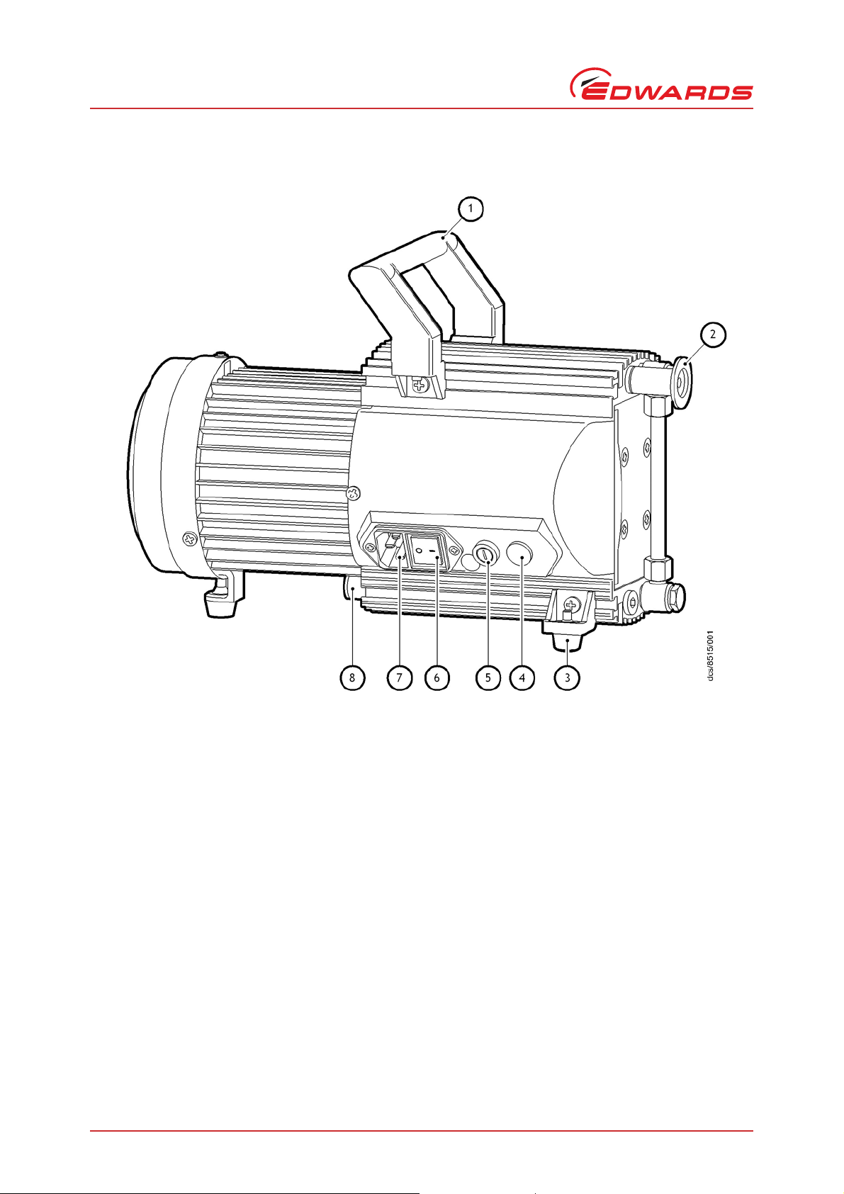
1. Handle (removable)
2. Inlet (small flange) NW16
3. Pump feet (adjustable)
4. Voltage selector switch
5. Fuse holder
6. Mains switch
7. Mains input
8. Outlet (silencer)
Introduction
Figure 1 - General view of XDD 1 with dual-voltage motor
Page 4 © Edwards Limited 2010. All rights reserved.
Edwards and the Edwards logo are trademarks of Edwards Limited.
Page 9
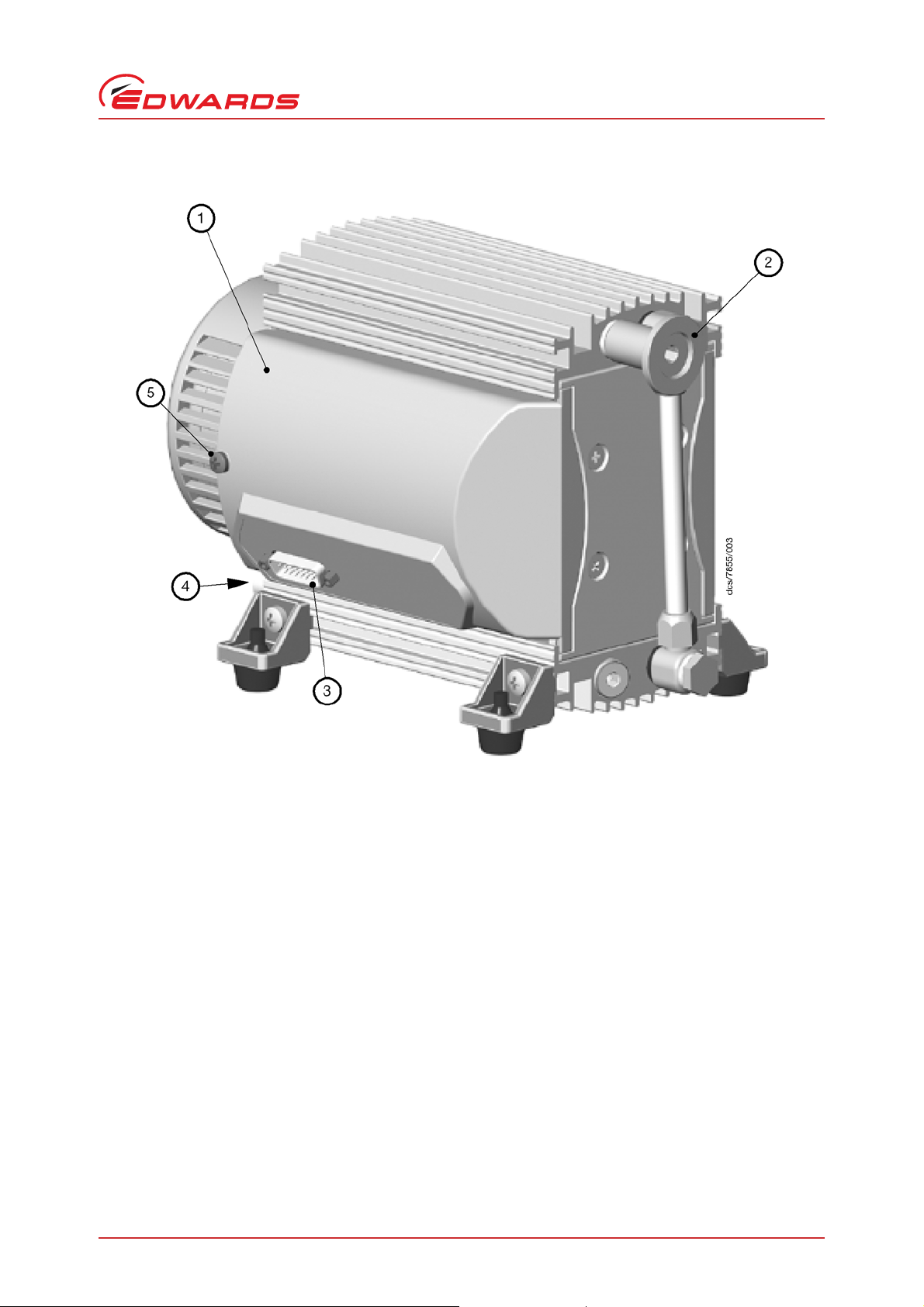
Figure 2 - General view of XDD 1 24 V DC
1. Cover of the circuit board
2. Inlet (small flange) NW 16
3. Male 15 pin D-connector
4. Outlet (silencer) at lower side
5. Screw to secure cover
A746-02-885 Issue A
Introduction
© Edwards Limited 2010. All rights reserved. Page 5
Edwards and the Edwards logo are trademarks of Edwards Limited.
Page 10

A746-02-885 Issue A
This page has been intentionally left blank.
Page 6 © Edwards Limited 2010. All rights reserved.
Edwards and the Edwards logo are trademarks of Edwards Limited.
Page 11

A746-02-885 Issue A
2Technical data
Table 1 - Electrical data
Par ameter XDD1 115/230 V 50/60 Hz XDD1 24 V DC
Motor power kW 0.08 0.064
Maximum permitted range of supply voltage
(±10%)
Maximum rated current:
100-120 V 50/60 Hz A 1.6 / 1.7 200-230 V 50/60 Hz A 0.8 / 0.85 24 V DC A - 7
Motor protection Thermal cut-out, manual reset Temperature sensor on the PCB
Fuse 20 mm x 5 mm, 250 V,
*
Voltage selection switch
Attention
100-120 V 50/60 Hz
200-230 V 50/60 Hz
2.5 A type T
*
24 V DC
(current limitation)
Technical data
Table 2 - Performance data
Parameter
3
Pumping speed (ISO 21360) m
Ultimate vacuum (absolute) mbar 1.5 < 1.0 (700 rpm)
No-load speed min
Maximum permissible outlet pressure (absolute) bar 1.1
Maximum pressure difference between inlet and outlet bar 1.1
*
Factory set
Table 3 - Environmental operating and storage data
Parameter XDD1 115/230 V XDD1 24 V DC
Degree of protection IEC 529 IP 40 IP 20
Permitted ambient temperature storage / operation °C -10 to +60 / +10 to +40
Permitted relative atmospheric moisture during
operation (no condensation)
Maximum operating altitude m 2000
IEC rated pollution degree 2
Sound level dBA 45
Area of use Indoor use only
/h 1.2 / 1.4 1.7 (2200 rpm)
%30 to 85
XDD1 115/230 V
-1
50/60 Hz
1500 / 1800 100 - 2200
XDD1 24 V DC
1.4 (1700 rpm)
*
© Edwards Limited 2010. All rights reserved. Page 7
Edwards and the Edwards logo are trademarks of Edwards Limited.
Page 12

A746-02-885 Issue A
Technical data
Table 4 - Mechanical data
Parameter XDD1 115/230 V XDD1 24 V DC
Mass kg 6.7 4.1
Overall dimensions Refer to Figure 3 Refer to Figure 4
Inlet connection Small flange NW 16
Outlet connection Silencer G 1/8 inch
Table 5 - Materials data
Components Wetted parts
Housing cover Aluminium
Head cover Aluminium
Diaphragm clamping disc Aluminium
®
Valve FPM (e.g. Viton
Diaphragm PTFE -FPM (e.g. Viton
Inlet (small flange) Stainless steel
Outlet (silencer) Aluminium / silicon caoutchouc
Hose PE
Fitting Aluminium anodized
)
®
) sandwich
Page 8 © Edwards Limited 2010. All rights reserved.
Edwards and the Edwards logo are trademarks of Edwards Limited.
Page 13

Figure 3 - Dimensional drawing XDD 1 (dual-voltage motor)
A746-02-885 Issue A
Technical data
© Edwards Limited 2010. All rights reserved. Page 9
Edwards and the Edwards logo are trademarks of Edwards Limited.
Page 14

A746-02-885 Issue A
Technical data
Figure 4 - Dimensional drawing XDD 1 24 V DC
Page 10 © Edwards Limited 2010. All rights reserved.
Edwards and the Edwards logo are trademarks of Edwards Limited.
Page 15

A746-02-885 Issue A
CAUTION
CAUTION
WARNING
1. Voltage selector switch
3 Installation
Note: A suitably trained or qualified technician must carry out the following procedures.
3.1 Electrical connection
3.1.1 XDD1 dual-voltage motor
Ensure that the motor is correctly configured for your electrical supply. If you operate the pump when the motor
is not correctly configured for the electrical supply, you will damage the motor.
Do not change the voltage selector switch while the pump is connected to the mains supply.
Figure 5 - Adjust the supply voltage
Installation
1. Selecting 115 covers a voltage supply range of 100 V to 120 V.
2. Selecting 230 covers a voltage supply range of 200 V to 240 V.
Ensure that the voltage shown on the voltage selector switch (Figure 5, item 1) corresponds with your electrical
supply voltage. If it does not, you must change the configuration of the pump motor using the voltage selector switch
to match your supply voltage. Use a screw driver to adjust the selector switch to the correct voltage.
Ensure that the electrical installation of the XDD1 mains pump conforms with your local and
national safety requirements. It must be connected to a suitably fused and protected electrical
supply and suitable earth point. For electrical data refer to Table 1.
© Edwards Limited 2010. All rights reserved. Page 11
Edwards and the Edwards logo are trademarks of Edwards Limited.
Page 16

A746-02-885 Issue A
Installation
Figure 6 - Replacing the motor fuse (dual-voltage motor)
1. Carefully remove the fuse holder at the side of the pump (refer to Figure 1, item 5).
2. Replace the defective fuse with a 2.5 A type T and secure the fuse carrier back into its holder.
3.1.2 XDD1 24 V dc
The pump has been factory set to a constant pumping speed when connected to a 24 V DC (=/-10%) supply. The pump
can also be controlled using an external analogue 0-10 V signal. Use a suitable connector mating half (not supplied)
to connect the electrical supplies and your control equipment to the connector on the logic interface cable. When
you make the electrical connections to the XDD 1, refer to Table 6 for full details of the logic interface connections.
Table 6 - Logic interface connector pins
Pin number Signal Use
2 Control / monitor: 0 V signal 4 XDD 1 identity
9 Speed (0-10 V) To control motor speed
8, 13, 14 Electrical supply: 0 V Use all pins for connection!
1, 6, 11 Electrical supply 24 V Use all pins for connection!
Page 12 © Edwards Limited 2010. All rights reserved.
Edwards and the Edwards logo are trademarks of Edwards Limited.
Page 17

Figure 7 - Internal speed setting
1. Potentiometer setting
A746-02-885 Issue A
Installation
3.2 Configure the XDD1 24V dc internal speed setting
There are two internal speed settings, use the following procedure to adjust the internal speed control (refer to
Figure 7).
Remove the screw which secures the cover to the circuit board (refer to Figure 2, item1) Move the cover carefully
and only as far as necessary. Using a screw dr iver, turn the potentiom et er t o one of tw o posi ti ons . Set t o posi ti on 2
for normal speed or position 3 if maximum throughput is required (refer to Figure 7). Assemble the cover in reverse
order.
3.3 Configuring the XDD1 24V dc for external analogue (0 - 10 V) speed control
Remove the screw which secures the cover to the circuit board (refer to Figure 2, item1) Move the cover carefully
and only as far as necessary. Using a screw driver turn the potentiometer anti-clockwise to position 1 (refer to
Figure 7). Assemble the cover in reverse order. Apply external analogue 0-10 V signal for motor speed control.
Voltage input: analogue 0 V....10 V
<0.5 V : Pump stopped
0.5 V to 10 V : Linear increase of the motor speed (~100 rpm to 2200 rpm)
Note: Pump runs smoothly only at speeds > 200 rpm ( > ~0.9 V).
© Edwards Limited 2010. All rights reserved. Page 13
Edwards and the Edwards logo are trademarks of Edwards Limited.
Page 18

A746-02-885 Issue A
Installation
3.4 Notes regarding the motor speed
Operating the pump at high motor speeds increases the pump throughput, this will also cause the pump to generate
more heat. Ensure there is adequate ventilation especially when using the pump within confined spaces or
enclosures.
Operating the pump at low motor speeds increases the ultimate vacuum performance, this will also increase the
lifetime of the diaphragm and valves.
Page 14 © Edwards Limited 2010. All rights reserved.
Edwards and the Edwards logo are trademarks of Edwards Limited.
Page 19

A746-02-885 Issue A
CAUTION
4Use and operation
4.1 Installing in a vacuum system
The pump can be mounted in any orientation.
Avoid throttling losses by using connecting pipes with large diameter and keep them as short as possible.
Reduce the transmission of vibration and prevent loading due to rigid pipelines. Insert elastic hoses or flexible
elements as couplings between the pump and rigid pipes.
Note: Flexible elements tend to shrink when evacuated.
Use a suitable valve to isolate the pump from the vacuum system to allow the pump to warm up before condensable
vapours are pumped or to clean the pump before it is switched off.
Connect the exhaust to a suitable treatment plant to prevent the discharge of dangerous gases and vapours to the
surrounding atmosphere. Use a catchpot to prevent the drainage of contaminated condensate back into the pump.
4.2 Prior to use
Use and operation
Note: Max. ambient temperature: 40 °C.
Make sure ventilation is adequate if pump is installe d in a housing or if ambient temperature is elevated. Keep a
distance of min. 20 cm between fans and ambient parts.
When assembling, ensure vacuum-tightness. After assembly, check the complete system for leaks.
4.3 During operation
Do not start or operate the pump if pressure at the outlet is higher than 1.1 bar absolute. Attempts to start or
operate the pump at higher pressure may cause blockade and damage of the motor.
The pump achieves its pumping speed, ultimate total vacuum and vapour pumping rate only at operating
temperature (after approx. 15 minutes).
Prevent internal condensation, transfer of liquids or dust. The diaphragm and valves will be damaged, if liquids are
pumped in significant amounts.
4.3.1 Pumps with dual-voltage motor
Motor is shut down by a thermal cutout in the winding. Manual reset is necessary. Switch off the pump or isolate the
equipment from mains. Wait approx. five minutes before restarting the pump. Identify cause of failure and eliminate.
Note: Pump starts again after power failure.
4.3.2 Pumps with 24 V dc voltage
The motor is protected by a temperature sensor at the circuit board (current limitation if the tempera t ure at t he
circuit board is higher than 70°C).
© Edwards Limited 2010. All rights reserved. Page 15
Edwards and the Edwards logo are trademarks of Edwards Limited.
Page 20

A746-02-885 Issue A
Use and operation
4.4 Shutdown
4.4.1 Short term
Fault Action
Has the pump been exposed to condensate? Allow the pump to continue to run at atmospheric
pressure with inlet open for a few minutes.
Has the pump been exposed to media which may
damage the pump materials or forms deposits?
4.4.2 Long term
z Take measures as described in section short-term shutdown.
z Separate pump from the apparatus.
z Close inlet and outlet port (e. g. with transport caps).
z Store the pump in dry conditions.
Check and clean pump heads if necessary.
Page 16 © Edwards Limited 2010. All rights reserved.
Edwards and the Edwards logo are trademarks of Edwards Limited.
Page 21

A746-02-885 Issue A
CAUTION
WARNING
WARNING
WARNING
5Maintenance
Ensure that maintenance is done only by suitably trained and supervised technicians. Ensure that the maintenance
technician is familiar with the safety procedures which relate to the product processed by the vacuu m s ystem and
that the equipment, if necessary, is appropriately decontaminated before starting maintenance. Obey local and
national safety regulations.
Before starting maintenance vent the system, isolate the pump and other components from the
vacuum system and the electrical supply, drain condensate and allow sufficient cooling of the
pump.
Before starting maintenance, wait two minutes after isolating the equipment from mains to allow
the capacitors to discharge.
In order to comply with law (occupational, health and safety regulations, safety at work law and regulations for
environmental protection) vacuum pumps, components and measuring instruments returned to the manufacturer can
be repaired only when certain procedures (see section Return of Edwards Equipment - Procedure
(Forms HS 1 and HS 2) are followed.
5.1 Replacing diaphragms and valves
Maintenance
Please read section Replacing diaphragms and valves completely before starting maintenance.
Note: The images of the pumps may differ slightly, this does not influence replacing the diaphragm and valves.
All bearings are encapsulated and are filled with long-life lubricant, under normal operating conditions these parts
are maintenance free.
The valves and the diaphragms are wear parts. If the rated ultimate vacuum is no longer achieved, the pump interior,
the diaphragms and the valves must be cleaned and the diaphragms and valves must be checked for cracks or other
damage.
Depending on individual cases it may be efficient to check and clean the pump heads on a regular basis. In case of
normal wear the lifetime of the diaphragms and valves is > 10000 operating hours.
Prevent internal condensation, transfer of liquids or dust. The diaphragm and valves will be damaged, if liquids
are pumped in significant amount.
If the pump is exposed to corrosive gases or vapour or in case of deposits, maintenance should be carried out
frequently.
Note: Regular maintenance will improve the lifetime of the pump and also protect both man and environment.
Before starting maintenance vent the system, isolate the pump and other components from the
vacuum system and the electrical supply.
Drain condensate if applicable, avoid the release of pollutants. Allow sufficient cooling of the pump.
© Edwards Limited 2010. All rights reserved. Page 17
Edwards and the Edwards logo are trademarks of Edwards Limited.
Page 22

A746-02-885 Issue A
CAUTION
WARNING
WARNING
Maintenance
Ensure that the pump cannot be operated accidentally. Never operate the pump if covers or other parts of the
pump are disassembled. Never operate a defective or damaged pump.
Ensure that the maintenance technician is familiar with the safety procedures which relate to the products proc essed
by the pumping system. The pump might be contaminated with the process chemicals that have been pumped during
operation. Ensure that the pump is decontaminated before maintenance and take adequate precautions to protect
people from the effects of dangerous substances if contamination has occurred.
Wear appropriate safety-clothing when you come in contact with contaminated components.
For cleaning or removing deposits of the valves and diaphragms, use a suitable solvent. The use of
any solvents must be used in accordance with your local health and safety regulations.
Page 18 © Edwards Limited 2010. All rights reserved.
Edwards and the Edwards logo are trademarks of Edwards Limited.
Page 23

Figure 8 - View of the disassembled pump head parts
1. Housing cover
2. VS seal
3. Bearing flange
4. Housing
5. Rod
6. Diaphragm support disc
7. Diaphragm
8. Diaphragm clamping disc with connecting screw
9. Head cover
10.Valve
11.VS seal
A746-02-885 Issue A
Maintenance
© Edwards Limited 2010. All rights reserved. Page 19
Edwards and the Edwards logo are trademarks of Edwards Limited.
Page 24

A746-02-885 Issue A
1. Diaphragm key SW 46 (included in service kit)
2. Open-ended wrench w/f 14
3. Hex key w/f 4/5
4. Phillips screw driver size 2
1. Bearing flange
Maintenance
Figure 9 - Tools required
5.1.1 Cleaning and inspecting the pump heads
Use open-ended wrench to remove fitting at the pump head and remove together with connecting hose.
Note: Do not remove bearing flange (1).
Figure 10 - Remove the fitting at the pump head
Page 20 © Edwards Limited 2010. All rights reserved.
Edwards and the Edwards logo are trademarks of Edwards Limited.
Page 25

Remove two screws at the handle and remove together with handle.
WARNING
Figure 11 - Remove the handle
Never remove parts by using a spiky or sharp-edged tool (e. g. screw driver), we recommend to
use a rubber mallet or compressed air (to be blown carefully into port).
A746-02-885 Issue A
Maintenance
Use hex key to remove six socket head screws from pump head and remove upper housing (housing cover and head
cover).
Figure 12 - Remove the housing cover and head cover
© Edwards Limited 2010. All rights reserved. Page 21
Edwards and the Edwards logo are trademarks of Edwards Limited.
Page 26

A746-02-885 Issue A
WARNING
Maintenance
1. Remove head cover from housing cover and check valves. Note position of valve s and remove.
2. Replace valves if necessary.
3. If necessary, use a suitable solvent to remove deposits.
4. Check diaphragm for damage and replace if necessary.
Figure 13 - Remove the head cover from the housing cover
5.1.2 Replacing the diaphragm
Never use a spiky or sharp-edged tool to lift the diaphragm.
1. Lift diaphragm carefully.
2. Apply pressure to the clamping disc beside the diaphragm to bring connecting rod into upper turning point
position if necessary.
3. Use diaphragm key to grip under the diaphragm to the diaphragm support disc.
4. Apply pressure to the diaphragm clamping disc to bring the diaphragm into lower turning point position. Press
diaphragm key against diaphragm clamping disc and unscrew diaphragm support disc with diaphragm.
5. If the old diaphragm is difficult to separate from the support disc, immerse the assembly in a suitable solvent in
order to aid separation of the two parts.
Page 22 © Edwards Limited 2010. All rights reserved.
Edwards and the Edwards logo are trademarks of Edwards Limited.
Page 27

Figure 14 - Lift the diaphragm
CAUTION
CAUTION
A746-02-885 Issue A
Maintenance
Check for washers under clamping disc. Do not mix the washers from the different heads. Make sure that the
original number is reassembled at the individual pump head.
6. Position new diaphragm between diaphragm clamping disc with square head screw and diaphragm support disc.
Note: Position diaphragm with white PTFE side to diaphragm clamping disc (to pump chamber).
Figure 15 - Position a new diaphragm
7. Lift diaphragm at the side and position carefully together with diaphragm clamping disc and diaphragm support
disc in the diaphragm key.
Avoid damage of the diaphragm: Do not crack diaphragm in a way that light lines at the diaphragm upper side
occur.
8. Smaller number of washers: The pump will not attain final vacuum. More washers: Clamping disc will hit head
cover; noise or even blockage of the pump.
© Edwards Limited 2010. All rights reserved. Page 23
Edwards and the Edwards logo are trademarks of Edwards Limited.
Page 28

A746-02-885 Issue A
WARNING
Maintenance
Figure 16 - Diaphragm clamping disc
5.1.3 Assembling pump heads
Do not turn or change housing covers!
1. Make sure that the square head screw of the diaphragm clamping disc is correctly se ated in the guide hole of the
diaphragm support disc.
2. Assemble diaphragm clamping disc, diaphragm and diaphragm support disc to co nnecting rod.
3. Position washers if available between diaphragm support disc and rod.
Figure 17 - Assemble the diaphragm assembly to the connecting rod
4. Bring diaphragm into a position in which diaphragm is in contact with housing and centred with respect to bore.
Page 24 © Edwards Limited 2010. All rights reserved.
Edwards and the Edwards logo are trademarks of Edwards Limited.
Page 29

Figure 18 - Position the diaphragm
CAUTION
5. Assemble head cover and valves. Check for correct position (refer to Figure 19 below).
Figure 19 - Assemble the head cover and valves
A746-02-885 Issue A
Maintenance
Obey position and orientation of the head covers and the valves definitely.
© Edwards Limited 2010. All rights reserved. Page 25
Edwards and the Edwards logo are trademarks of Edwards Limited.
Page 30

A746-02-885 Issue A
1. Valves at the outlet (round
centred opening under valve)
2. Valves at the inlet
(kidney-shaped opening beside valve)
Maintenance
Figure 20 - Scheme pump head with head covers
Figure 21 - Scheme pump head with head covers and valves
6. Position housing cover.
7. Move housing cover slightly to make sure that the head covers are correctly positioned.
8. Screw in six socket head screws fixing housing cover crosswise first slightly, then tighten.
Note: Do not tighten until head cover is in contact with housing, max. torque 6 Nm.
Page 26 © Edwards Limited 2010. All rights reserved.
Edwards and the Edwards logo are trademarks of Edwards Limited.
Page 31

Figure 22 - Position the housing cover
A746-02-885 Issue A
Maintenance
9. Assemble handle with screws and tighten.
Note: Check for correct position of the handle over the centre of gravity of the pump. The handle is in correct
position if the end of the handle is positioned over the end of the housing cover.
Figure 23 - Assemble the handle
© Edwards Limited 2010. All rights reserved. Page 27
Edwards and the Edwards logo are trademarks of Edwards Limited.
Page 32

A746-02-885 Issue A
Maintenance
5.1.4 Assembling fittings
1. Use open ended wrench to reconnect fittings with connection hose to pump heads.
2. Fix the ring nut when tightening the hollow bolt.
Figure 24 - Assemble the fitting at the pump head
5.1.5 If the pump does not achieve the ultimate pressure
In case the diaphragms and valves have been re placed, a run-in per iod of several hours is required before the pump
achieves its ultimate vacuum.
If pump does not achieve the ultimate total pressure:
z Check hose connectors between pump heads and manifolds for leaks.
z If necessary recheck pump chamber.
Page 28 © Edwards Limited 2010. All rights reserved.
Edwards and the Edwards logo are trademarks of Edwards Limited.
Page 33

Table 7 - Troubleshooting
Fault Possible cause Remedy
Pump fails to start or stops
immediately.
Pump does not achieve
ultimate total pressure or
normal pumping speed.
Pump too noisy. Atmospheric or high pressure
Pump seized. Contact your supplier.
Supply voltage is missing or
too low?
Only 24 V DC version:
Control signal for motor
speed is missing?
Pressure in outlet pipeline too
high?
Only pumps with dualvoltage motor: Motor
overloaded?
The motor fuse has blown Replace fuse (refer to Table 1).
Centring ring not correctly
positioned or leak in the
pipeline or vacuum system?
Long narrow line? Use line with larger diameter,
Pump has been exposed to
condensate?
Deposits have been formed
inside the pump?
V alves or diaphragm
damaged?
Outgasing substances or
vapour generated in the
process?
Only 24 V DC version:
Pump temperature too high
(reduced motor speed)?
at inlet port?
Diaphragm clamping disc
loose?
None of above mentioned
causes?
Check or connect supply
voltage.
Check control signal.
Remove blockade in line,
open valve.
Manual reset is necessary.
Switch off the pump or
isolate the equipment from
mains. Wait approx. five
minutes before restarting the
pump. Identify cause of
failure and eliminate.
Identify and eliminate cause of failure.
Check pump with a vacuum
gauge directly at pump inlet
port, check connections and
line.
length as short as possible.
Run pump at atmospheric
pressure for a few minutes.
Clean and inspect pump
heads.
Replace valves and/or
diaphragms.
Check process parameters.
Ensure sufficient cooling of
the pump or reduce inlet
pressure.
Connect hose to pump outlet.
Perform maintenance.
Contact your supplier.
A746-02-885 Issue A
Maintenance
© Edwards Limited 2010. All rights reserved. Page 29
Edwards and the Edwards logo are trademarks of Edwards Limited.
Page 34

A746-02-885 Issue A
This page has been intentionally left blank.
Page 30 © Edwards Limited 2010. All rights reserved.
Edwards and the Edwards logo are trademarks of Edwards Limited.
Page 35

A746-02-885 Issue A
6 Storage and disposal
6.1 Storage
Use the following procedure to store the pump:
Close the vacuum system isolation valve to prevent suckback into the vacuum system. Switch off the pump using the
on/off switch on the motor. Disconnect the pump from the electrical supply. Purge your vacuum system and the pump
with dry nitrogen and disconnect the pump from your vacuum system. Place and secure protective covers over the
inlet and outlet ports.
Store the pump in cool, dry conditions until required for use.
6.2 Disposal
Dispose of the pump and any components from it safely in accordance with all local and national safety and
environmental requirements. Particular care must be taken with components which have been contaminated with
dangerous process substances.
Do not incinerate fluoroelastomer seals and O-rings.
Storage and disposal
© Edwards Limited 2010. All rights reserved. Page 31
Edwards and the Edwards logo are trademarks of Edwards Limited.
Page 36

A746-02-885 Issue A
This page has been intentionally left blank.
Page 32 © Edwards Limited 2010. All rights reserved.
Edwards and the Edwards logo are trademarks of Edwards Limited.
Page 37

A746-02-885 Issue A
7 Spares and accessories
7.1 List of spare parts
Table 8 - Spare parts
Item number Description
A746-01-700 Inlet flange spare XDD1
A746-01-701 VS seal spare XDD1
A746-01-702 Exhaust silencer spare XDD1
A746-01-800 Diaphragm service kit XDD1
A746-01-703 Fan cover white, XDD 1, 115/230 V, 50/60 Hz
A746-01-704 Motor cover white, XDD 1, 24 V DC
A746-01-705 Anti-vibration mount
Spares and accessories
© Edwards Limited 2010. All rights reserved. Page 33
Edwards and the Edwards logo are trademarks of Edwards Limited.
Page 38

A746-02-885 Issue A
This page has been intentionally left blank.
Page 34 © Edwards Limited 2010. All rights reserved.
Edwards and the Edwards logo are trademarks of Edwards Limited.
 Loading...