

Page 1
W959-000-01
Revision
F
October,
96
Instruction
Manual
TCU
40/80
Single
Channel
Temperature
Control
Unit
EDWARDS
Edwards
High
Vacuum
International
One
Edwards
Park
301
Ballardvale
Street
Wilmington,MA01887
Telephone:
(508)
658-5410
Telex:
710-347-7672
Fax:
(508)658-7969
Page 2
Declaration
of
Conformity
We,
Edwards
High
Vacuum
International,
One
Edwards
Park
301
Ballardvale
St.
Wilmington,MA01887
declare
under
our
sole
responsibility
that
the
product(s)
TCU
40/80
Temperature
Control
Unit
W95000000
to
which
this
declaration
relatesisin
confonnity
with
the
following
standard(s)
or
other
normative
document(s)
BSIEC1010-1
BS
EN50O81-1
BSEN50082-1
following
the
provisions
of
89/392/EEC
89/336/EEC
73/023/EEC
Safety
Requirements
for
Electrical
Equipment
for
Measurement,
Control
and
Laboratory
Use.
Electromagnetic
Compatibility,
General
Emission
Standard.
Generic
Standard
Class:
Domestic,
Commercial&Light
Industry.
Electromagnetic
Compatibility,
General
Immunity
Standard.
Generic
Standard
Class:
Domestic,
Commercial&Light
Industry
Machinery
Safety
Directive
Electromagnetic
Compatibility
Directive
Low
Voltage
Directive
0
Dr.A.P.
Troup,
DirectorofTechnology
Date
and
Place
This
product
has
been
manufactured
underaquality
system
registered
to
ISO900I
EDWARDS
Page 3
CONTENTS
Section
Title
Page
1
PREFACE
1
1.1
Safety
considerations
1
2
TCU
40/80
3
2.1
Scopeofthe
manual
3
2.2
Descriptionofthe
TCU
40/80
3
2.3
Lockout
procedure
3
2.4
Safety
features
4
3
QUICK
START
PROCEDURE
5
3.1
Power
up
5
3.2
Sctpoint
verification
5
4
PRODUCT
DESCRIPTION
6
4.1
Refrigeration
and
coolant
circuits
6
4.2
Refrigeration
9
4.2.1
If
coolingisrequired:
9
4.2.2
If
coolingisnot
required:
10
4.3
Coolant
circuit
10
4.4
Temperature
monitoring
10
4.5
Front panel
1
]
4.6
Rear
panel
13
4.7
Specifications
14
4.8
Dimensions
15
5
INSTALLATION
]6
5.1
Receiving
and
unpacking
16
5.2
Location
16
5.2.1
Securing
the
unit
16
5.2.2 Installing
the
secondary
containment
receptacle
16
5.2.3
Floor
levclers
16
5.3
Stacking
17
5.3.1
Tie-bolts
17
5.4
Facilities
17
5.4.1
Water
and
coolant
connections
18
5.4.2
Water
19
5.4.3
Coolant
19
5.4.4
Remote
connections
19
6
OPERATION
20
6.1
Preparation
20
6.2
Poweringupthe
TCU
40/80
20
6.3
Changing
the
setpoint
value
(SV1)
21
6.4
Temperature
controller
Pid
settings
21
6.5
Remote
set-point
22
6.6
Flow
rate
adjustment
22
/?^v
TCU
40/80
Temperature
Control
Unit
Page 4
7
MAINTENANCE
23
7.1
Hazard
warnings
23
7.2
Hazards
25
7.3
Filling
the
reservoir
26
7.4
Draining/bleeding
the
coolant
reservoir
26
7.5
Temperature
probe
calibration
27
7.6
Preventive
maintenance
schedule
27
7.7
Semi-annual
preventative
maintenance
28
7.7.1
Required
equipment
28
7.7.2
Preparation
28
7.7.3
Verify
system
status
28
7.7.4
Refrigeration
leak
check
28
7.7.5
Fluorinert
leak
check
28
7.7.6
Water
leak
check
28
7.7.7
Insulation repair
28
7.7.8
Lamp
check/replacement
29
7.8
Annual
preventative
maintenance
30
7.8.1
Required
equipment
30
7.8.2
Required
supplies
30
7.8.3
Solenoid
valve
coil
replacement
30
7.8.4
System
check
32
7.9
Preventive
maintenance
checklist
41
8
TROUBLESHOOTING
42
9
ACCESSORIES
AND
SPARE
PARTS
52
APPENDIX
54
ReturnofEdwards
Equipment-Procedure
(Form
HS1)
58
ReturnofEdwards
Equipment-
Declaration
(FormHS2)
59
Legal
notices,
limitations
and
disclaimers
60
MSDS
(material
safety
data
sheet)-
"SUVA"
HP62
61
'-""5\
TCU
40/80
Temperature
Control
Unit
Page 5
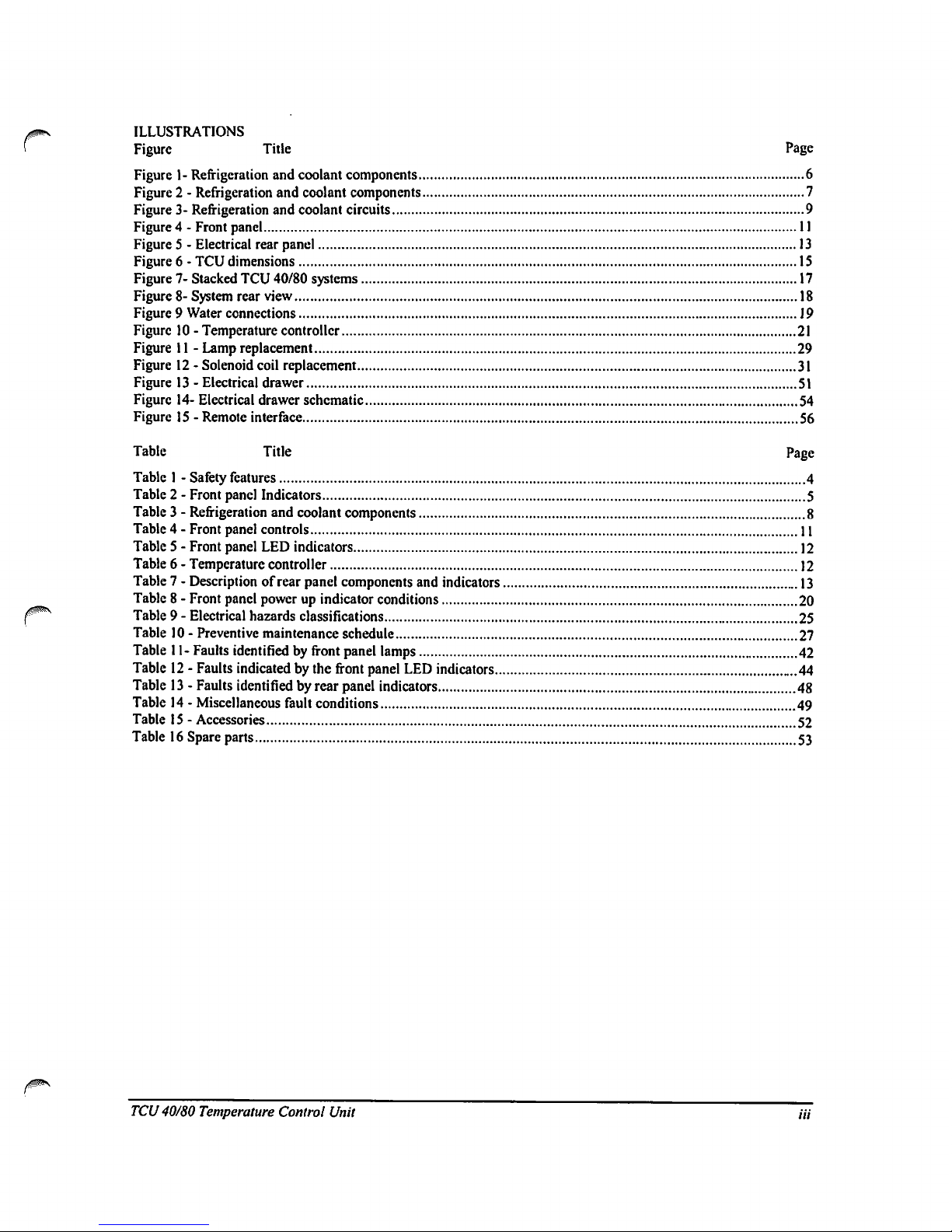
ILLUSTRATIONS
Figure
Title
Page
Figure1-Refrigeration
and
coolant
components
6
Figure2-
Refrigeration
and
coolant
components
7
Figure3-Refrigeration
and
coolant
circuits
9
Figure4-
Front panel
11
Figure5-
Electrical
rear
panel
13
Figure6-
TCU
dimensions
15
Figure7-Stacked
TCU
40/80
systems
17
Figure
8-System
rear
view
18
Figure9Water
connections
J9
Figure10-
Temperature
controller
21
Figure11-
Lamp
replacement
29
Figure12-
Solenoid
coil
replacement
31
Figure13-Electrical
drawer
51
Figure
14-Electrical
drawer
schematic
54
Figure15-
Remote
interface
56
Table
Title
Page
Table1-
Safety
features
4
Table2
-Frontpanel
Indicators
5
Table3-
Refrigeration
and
coolant
components
8
Table4-
Front
panel
controls
11
Table5-
Front
panel
LED
indicators
12
Table6-
Temperature
controller
12
Table7-
Description
of
rear
panel
components
and
indicators
13
Table8-
Front panel
powerupindicator
conditions
20
Table9-
Electrical
hazards
classifications
25
Table10-
Preventive
maintenance
schedule
27
Table
11-
Faults
identified
by
front
panel
lamps
42
Table12-
Faults
indicated
by
the
front
panel
LED
indicators
44
Table13-Faults
identified
by
rear
panel
indicators
48
Table14-
Miscellaneous
fault
conditions
49
Table15-Accessories
52
Table16Spare
parts
53
TCU
40/80
Temperature
Control
Unit
Hi
Page 6
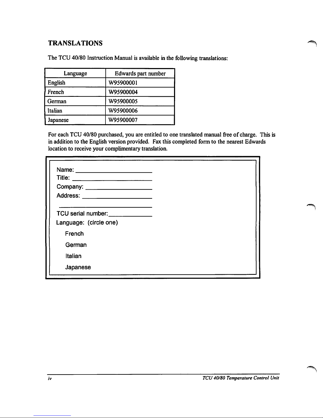
TRANSLATIONS
The
TCU
40/80
Instruction
Manualisavailable
in
the
following
translations:
Language
English
French
German
Italian
Japanese
Edwards
part
number
W95900001
W95900004
W95900005
W95900006
W95900007
For
each
TCU
40/80
purchased,
you
are
entitledtoone
translated
manual
freeofcharge.
This
is
in
additiontothe
English
version
provided.
Fax
this
completed
formtothe
nearest
Edwards
locationtoreceive
your
complimentary
translation.
Name:
Title:
Company:
Address:
TCU
serial
number:
Language:
(circle
one)
French
German
Italian
Japanese
TCU
40/80
Temperature
Control
Unit
Page 7
1
PREFACE
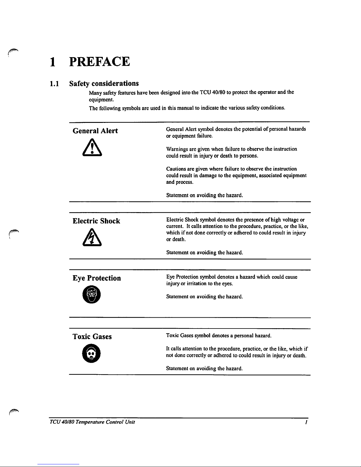
1.1
Safety
considerations
Many
safety features
have
been
designed
into
the
TCU
40/80toprotect
the
operator
and
the
equipment.
The
following
symbols
are
usedinthis
manualtoindicate
the
various
safety
conditions.
General
Alert
General
Alert
symbol
denotes
the
potential
of
personal
hazards
or
equipment
failure.
Warnings
are
given
when
failuretoobserve
the
instruction
could
resultininjuryordeathtopersons.
Cautions
are
given
where
failuretoobserve
the
instruction
could
resultindamagetothe
equipment,
associated
equipment
and
process.
Statementonavoiding
the
hazard.
Electric
Shock
Electric
Shock
symbol
denotes
the
presenceofhigh
voltage
or
current.Itcalls
attentiontothe
procedure,
practice,orthe
like,
whichifnot
done
correctlyoradheredtocould
resultininjury
or
death.
Statementonavoiding
the
hazard.
Eye
Protection
Eye
Protection
symbol
denotesahazard
which
could
cause
injuryorirritation
to
the
eyes.
Statementonavoiding
the
hazard.
Toxic
Gases
Toxic
Gases
symbol
denotesapersonal
hazard.
It
calls
attentiontothe
procedure,
practice,orthe
like,
which
if
not
done
correctly
or
adheredtocould
resultininjury or death.
Statementonavoiding
the
hazard.
TCU
40/80
Temperature
Control
Unit
Page 8
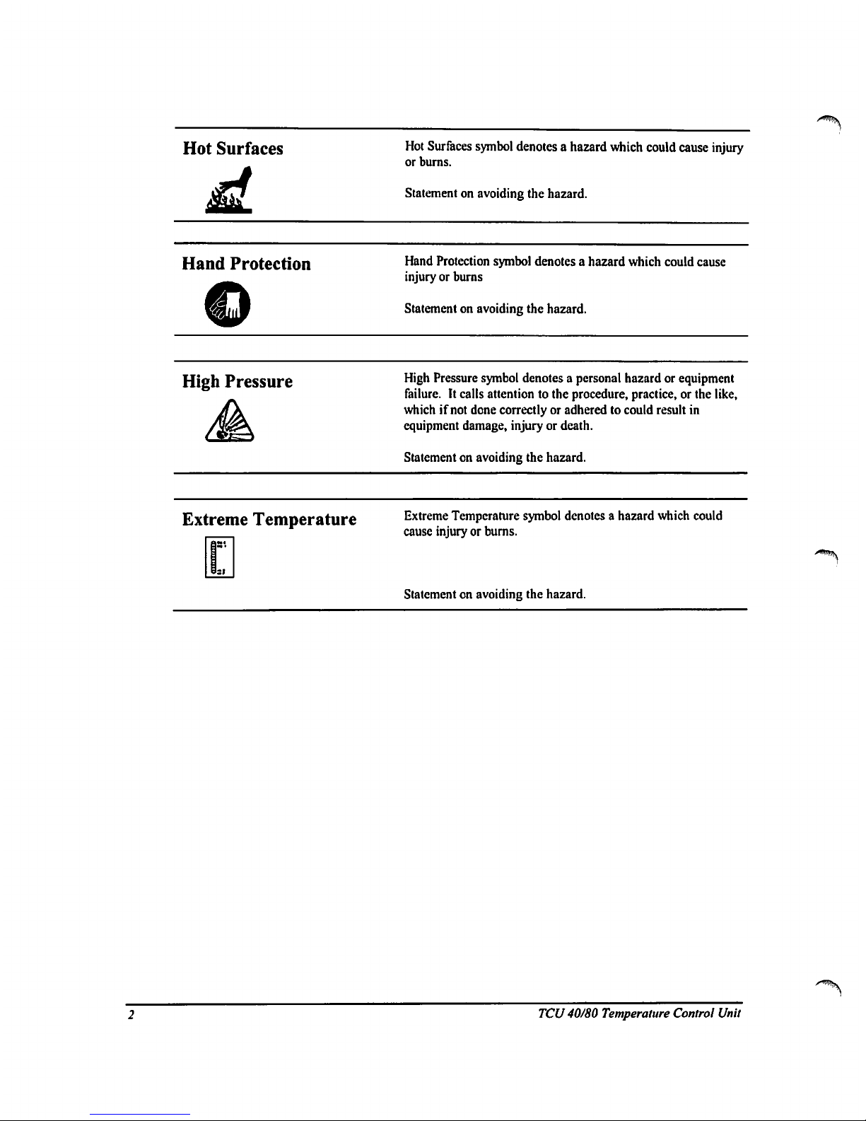
Hot
Surfaces
Hot
Surfaces
symbol
denotes a
hazard
which
could
cause
injury
or burns.
Statementonavoiding
the
hazard.
Hand
Protection
Hand
Protection
symbol
denotes a
hazard
which
could
cause
injuryorburns
Statementonavoiding
the
hazard.
High
Pressure
High
Pressure
symbol
denotesapersonal
hazardorequipment
failure.
It
calls
attention
to
the
procedure,
practice,
or
the
like,
whichifnot
done
correctlyoradheredtocould
result
in
equipment
damage,
injury
or death.
Statementonavoiding
the
hazard.
Extreme
Temperature
Extreme
Temperature
symbol
denotesahazard
which
could
cause
injuryorburns.
Statementonavoiding
the
hazard.
^
TCU
40/80
Temperature
Control
Unit
Page 9
2
TCU
40/80
2.1
Scopeofthe
manual
This
manual
provides
informationonthe
installation,
start-up
and
operationofEdwards
High
Vacuum
Model
40/80
Temperature
Control
Unit
(TCU
40/80).
The
Quick
Start
Procedureonpage5isastepbystep
guide
for
the
startupand
use
of an
installed,
working
system.
Installation,
startingonpage
16,
provides
instructions
and
information
for
installing
the
system.
The
installer
must
have
sufficient
technical
understanding
of
electrical
and
mechanical
systemstoproperly
use
this
information.
Operation,
starting
on page
20,
provides
more
complete
instructions
on
the
preparation
and
useofthe
system.
2.2
Description
of
the
TCU
40/80
The
TCU
40/80isa
single-channel
temperature
control
unit
engineered
for
temperature
controlofremote
heat
loads.
From
distancesuptoSOfeet,
the
TCU
40/80
can
cool
the
heat
load
generatedbythe
process
equipment.
The
coolant
circulates
through
the
TCU
40/80,
whereitis
cooledorheatedasrequired,
thenistransferred
to
the
process
equipment,
and
returnsina closed
loop.
The
TCU
40/80
maintains
supply
coolantata
temperature
between
-40°Cand
+80
°C,
selectable
in
0.1°Cincrements,
withatoleranceof±1.0
°C.
2.3
Lockout
procedure
To
prevent
accidental
or
unauthorized
startingofthe
TCU
40/80
during
maintenance,
disconnect
the
power
cord
from
the
receptacle
and
installanappropriate
lock-out
device
(Hubbell
Small
Plugout™
or
equivalent)
on
the
endofthe
power
cord.
0
TCU
40/80
Temperature
Control
Unit
Page 10
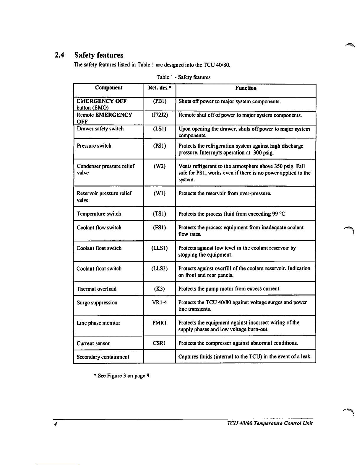
2.4
Safety
features
The
safety
features
listedinTable1are
designed
into
the
TCU
40/80.
TableI-
Safety
features
Component
EMERGENCY
OFF
button
(EMO)
Remote
EMERGENCY
OFF
Drawer
safety
switch
Pressure
switch
Condenser
pressure
relief
valve
Reservoir
pressure
relief
valve
Temperature
switch
Coolant
flow
switch
Coolant
float
switch
Coolant
float
switch
Thermal
overload
Surge
suppression
Line
phase
monitor
Current
sensor
Secondary
containment
Ref.
des.*
(PB1)
(J72J2)
(LSD
(PS1)
(W2)
(Wl)
(TS1)
(FS1)
(LLS1)
(LLS3)
(K3)
VR1-4
PMR1
CSR1
Function
Shuts
off
powertomajor
system
components.
Remote
shut
offofpowertomajor
system
components.
Upon
opening
the
drawer,
shuts
off
powertomajor
system
components.
Protects
the
refrigeration
system
against
high
discharge
pressure.
Interrupts
operationat300
psig.
Vents
refrigerant
to
the
atmosphere
above
350
psig.
Fail
safe
for
PS1,
works
evenifthereisno
power
appliedtothe
system.
Protects
the
reservoir
from
over-pressure.
Protects
the
process
fluid
from
exceeding99°C
Protects
the
process
equipment
from
inadequate
coolant
flow
rates.
Protects
against
low
levelinthe
coolant
reservoir
by
stopping
the
equipment.
Protects
against
overfill
of
the
coolant
reservoir.
Indication
on
front
and
rear
panels.
Protects
the
pump
motor
from
excess
current.
Protects
the
TCU
40/80
against voltage
surges
and
power
line
transients.
Protects
the
equipment
against
incorrect
wiringofthe
supply
phases
and low
voltage
burn-out.
Protects
the
compressor
against
abnormal
conditions.
Captures
fluids
(internaltothe
TCU)inthe
eventofa
leak.
•
See
Figure3on
page
9.
TCU
40/80 Temperature
Control
Unit
Page 11

3
QUICK
START
PROCEDURE
This
Quick
Start
procedureisfor
easy
start
up
and
operation
of an
installed
and
fully
working
TCU
40/80.Ifyour
TCU
40/80
is
not
installed,
gotoInstallation
on
page
16.
Detailed
operating
instructions
are
in
Operation
on page
20.
Ifatany
time an
alarm
occurs,
press
STOP
and
correct
the
fault
indicatedbythe
display
as
directedinthe
Troubleshooting
Guide
on
page
42.
Press
RESET
and
START
to
continue
operation.
3.1
Power
up
Before
applying
power,
verify
that
all
water
and
coolant
lines
are
connectedtothe
system.
The
handlesonboth
coolant
line
valves
shouldbein
the
open
position.
For
the
locationofthese
connections,
refer
to
Figure8on
page
18.
To
power up
the
TCU
40/80:
1.
READY
light
shouldbeon.Ifthe
ready
lightisnotonsee
Powering
Up
the
TCU
40/80onpage
20.
2.
Press
RESET.
Verify
that
front
panel
indicators
areasshowninthe
Reset
columnofTable2on
this
page.
3.
Press
START.
Verify
that front
panel
indicators
areasshowninthe
Start
Condition
columnofTable2on
this
page.
If in
steps
twoorthree
any
front
panel
indicators
do
not
match
Table2,refertothe
Troubleshooting
Guideonpage42for
corrective
action.
4.
Verify
that
the
coolant
pressure
gauge
(locatedonthe
front
access
panel)
reads
less
than
100
psig.
Table 2-Front
panel
Indicators
Indicator
POWER
ON
RESET
FACILITY
POWER
FACILITY
WATER
CIRCUIT
BREAKERS
COMPRESSOR
TEMPERATURE
FLOW
NORMAL
LEVEL
LOW
LEVEL
REMOTE
RTD
(optional)
Reset
Condition
Green
White
Green
Green
Green
Off
Green
Off
Green
OfT
Green
(if
used)
Start
Condition
Green
White
Green
Green
Green
Green
Green
Green
Green
Off
Green
(if
used)
3.2
Setpoint
verification
Verify
that
the
manual
mode
setpoint
value
(SV1)
displayedonthe
temperature
control
is
the
value
desired.Tochange
the
Setpoint
value
see
Changing
the Setpoint
Value
(SVl)onpage21.
Do
nottoexceed
the
normal
operating
parameters.
The
systemisdesigned
to
operate
from
-40°Cto
+80
°C.
TCU
40/80
Temperature
Control
Unit
Page 12
4
PRODUCT
DESCRIPTION
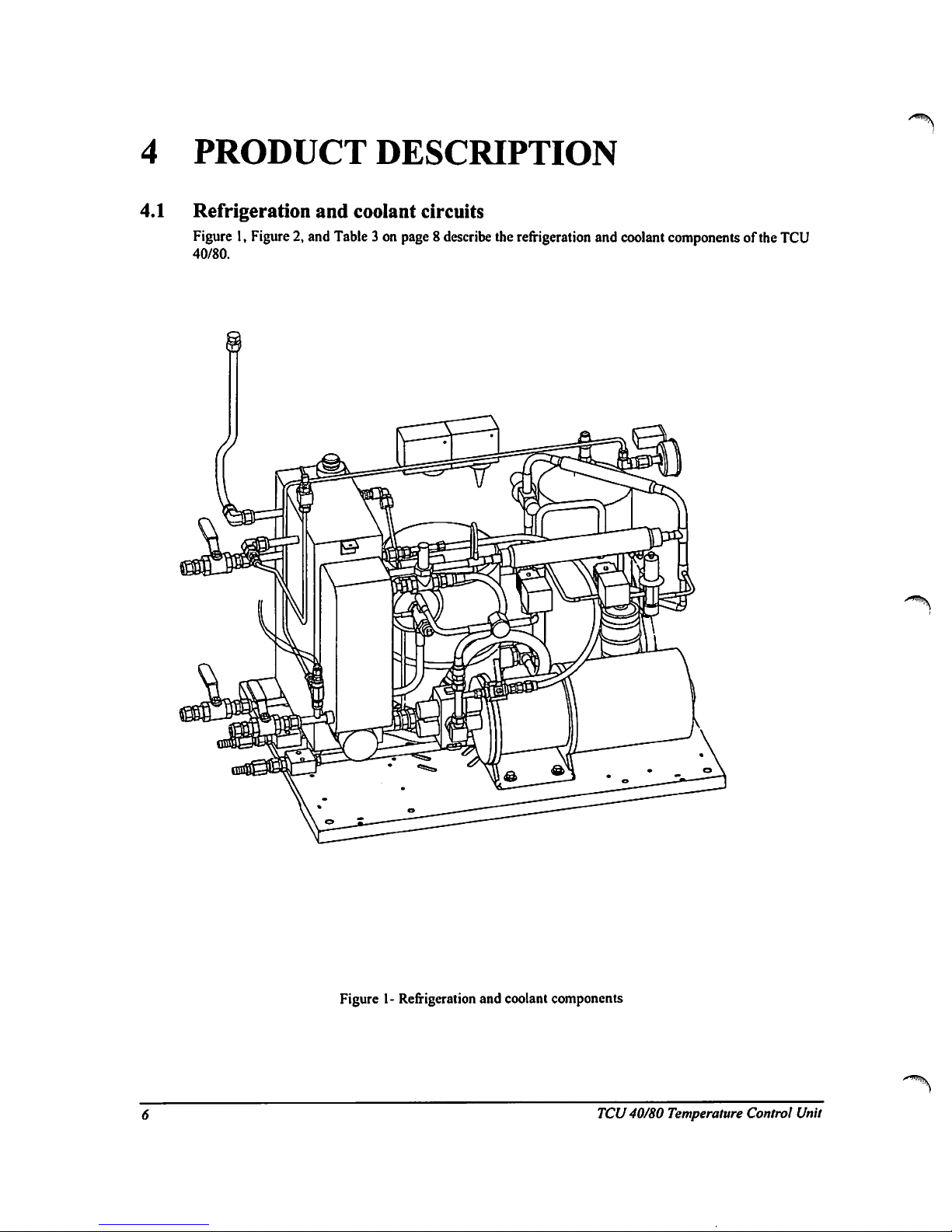
4.1
Refrigeration
and
coolant
circuits
Figure1,Figure2,and
Table3on page8describe
the
refrigeration
and
coolant
componentsofthe
TCU
40/80.
Figure1-Refrigeration
and
coolant
components
TCU40/80
Temperature
Control
Unit
Page 13
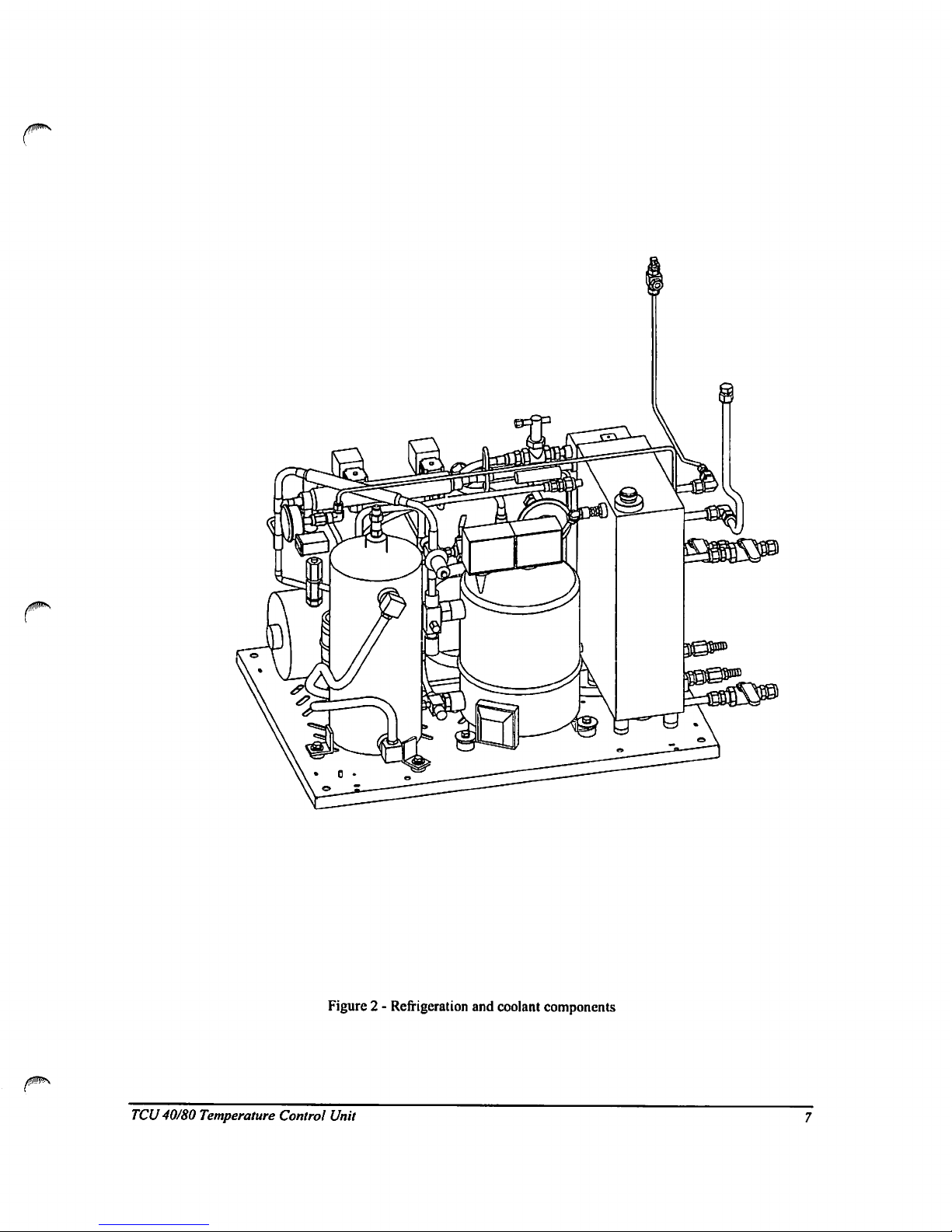
Figure2-
Refrigeration
and
coolant
components
TCU
40/80
Temperature
Control
Unit
Page 14
/^\
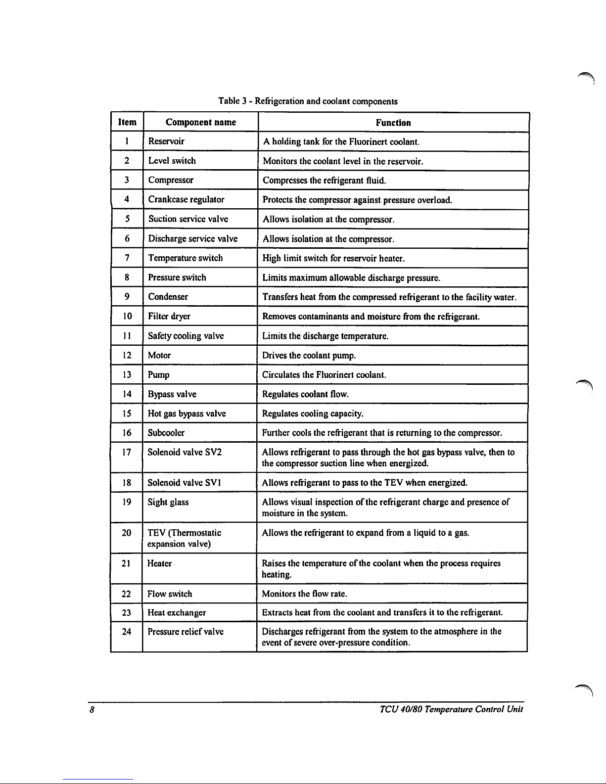
Table3-
Refrigeration
and
coolant
components
Item
I
2
3
4
5
6
7
8
9
10
11
12
13
14
15
16
17
18
19
20
21
22
23
24
Component
name
Reservoir
Level
switch
Compressor
Crankcase
regulator
Suction
service
valve
Discharge
service
valve
Temperature
switch
Pressure
switch
Condenser
Filter
dryer
Safety
cooling
valve
Motor
Pump
Bypass
valve
Hot
gas
bypass
valve
Subcooler
Solenoid
valve
SV2
Solenoid
valve
SV1
Sight
glass
TEV
(Thermostatic
expansion
valve)
Heater
Flow
switch
Heat
exchanger
Pressure
relief
valve
Function
A
holding
tank
for
the
Fluorinert
coolant.
Monitors
the
coolant
levelinthe
reservoir.
Compresses
the
refrigerant
fluid.
Protects
the
compressor
against
pressure
overload.
Allows
isolation
at
the
compressor.
Allows
isolationatthe
compressor.
High
limit
switch
for
reservoir
heater.
Limits
maximum
allowable
discharge
pressure.
Transfers
heat
from
the
compressed
refrigerant
to
the
facility
water.
Removes
contaminants
and
moisture
from
the
refrigerant.
Limits
the
discharge
temperature.
Drives
the
coolant
pump.
Circulates
the
Fluorinert
coolant.
Regulates
coolant
flow.
Regulates
cooling
capacity.
Further
cools
the
refrigerant
thatisreturningtothe
compressor.
Allows
refrigerant
to
pass
through
the
hot
gas bypass
valve,
then
to
the
compressor
suction
line
when
energized.
Allows
refrigerant
to
passtothe
TEV
when
energized.
Allows
visual
inspectionofthe
refrigerant
charge
and
presence
of
moistureinthe
system.
Allows
the
refrigerant
to
expand
fromaliquidtoa
gas.
Raises
the
temperature
of
the
coolant
when
the
process
requires
heating.
Monitors
the
flow
rate.
Extracts
heat
from
the
coolant
and
transfers
ittothe
refrigerant.
Discharges
refrigerant
from
the
systemtothe
atmosphereinthe
eventofsevere
over-pressure
condition.
TCU
40/80
Temperature
Control
Unit
Page 15
/
Bypass
vaSn
Oran
valve
I
RID
temperature
probe
Profisure
Gwlttfc
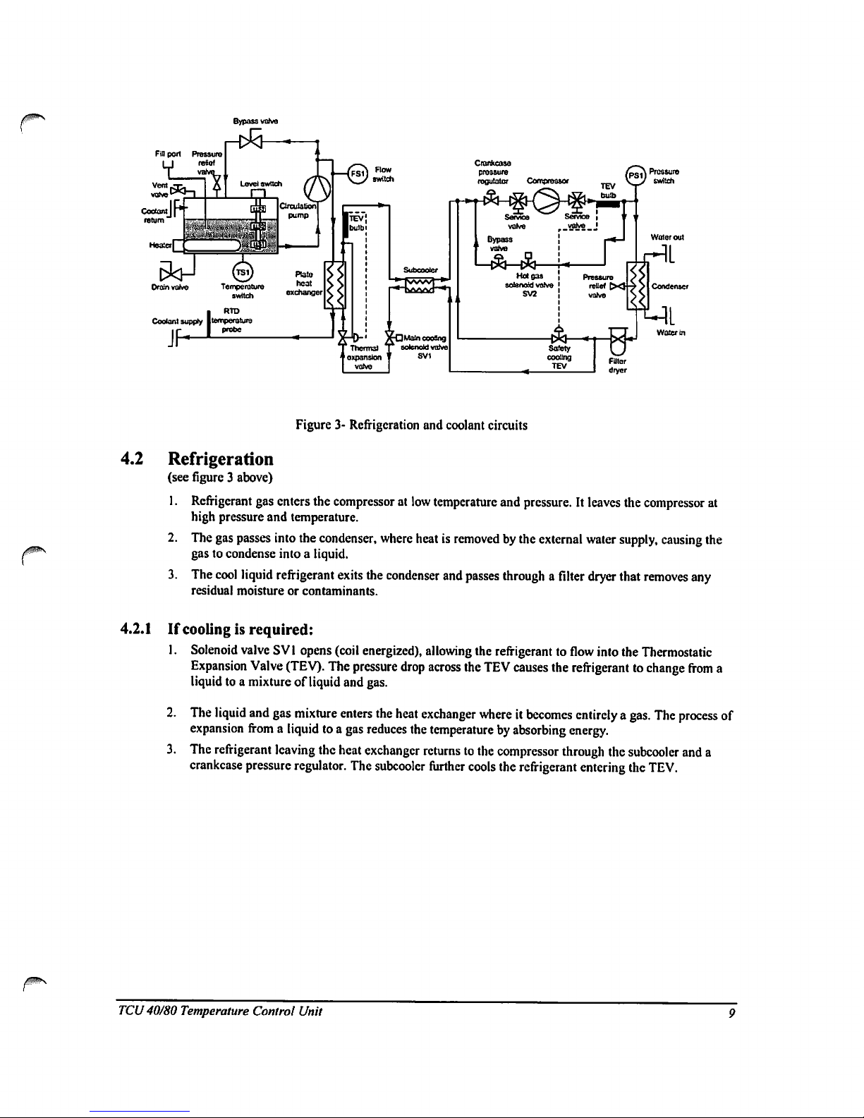
Figure3-Refrigeration
and
coolant
circuits
4.2
Refrigeration
(see
figure3above)
1.
Refrigerant
gas
enters
the
compressor
at
low
temperature
and
pressure.
It
leaves the
compressor
at
high
pressure
and
temperature.
2.
The
gas
passes
into
the
condenser,
where
heatisremovedbythe
external
water
supply,
causing
the
gastocondense
intoaliquid.
3.
The
cool
liquid
refrigerant
exits
the
condenser
and
passes
throughafilter
dryer
that
removes
any
residual
moistureorcontaminants.
4.2.1Ifcoolingisrequired:
1.
Solenoid
valve
SV1
opens
(coil
energized),
allowing
the
refrigerant
to
flow
into
the
Thermostatic
Expansion
Valve
(TEV).
The
pressure
drop
across
the
TEV
causes
the
refrigerant
to
change
from
a
liquidtoa
mixtureofliquid
and
gas.
2.
The
liquid
and
gas
mixture
enters
the
heat
exchanger
whereitbecomes
entirely
a
gas.
The
process
of
expansion
fromaliquidtoa
gas
reduces
the
temperature
by
absorbing
energy.
3.
The
refrigerant
leaving
the
heat
exchanger
returnstothe
compressor
through
the
subcooler
and
a
crankcase
pressure
regulator.
The
subcoolcr
further
cools
the
refrigerant
entering
the
TEV.
TCU
40/80
Temperature
Control
Unit
Page 16
4.2.2Ifcoolingisnot
required:
1.
Solenoid
valve
SVl
closes
(coil
de-energized).
2.
Hot
refrigerant
from
the
compressor
is
passed
through
SV2
(coil
energized)
andahot
gas
bypass
valve
before
returning
to
the
compressor
suction
line.
This
bypassing
allows
the
compressor
to
run
continuously.
3.
Cooling,
requiredtoprevent
the
compressor
from
overheating,
is
providedbyallowing
someofthe
liquid
from
the
condensertopass
through
the
safety
cooling
automatic
expansion
valve
into
the
suction
line,
thus
maintaining
the
discharge
gas
temperature
below99°C.
4.3
Coolant
circuit
Coolantispulled
from
the
reservoir
by
the
circulation
pump
and
transferred
to
the
heat
exchanger
where
itiscooledbythe
refrigeration
systemasrequired.
It
then
flowstothe
process
equipmentbymeansofthe
coolant
supply
hose.
The
coolant
returnstothe
TCU
40/80
reservoirbymeansofthe
coolant
return
hose.
The
coolant
system
requires8litersofcoolant
for
the
reservoir,
plus
the
volumeofthe
circulation
lines
and
any
other
spaces
filled
with
coolant
that
are
attachedtothe
TCU
40/80.
To
increase
the
coolant
temperature,
the
reservoir
usesanelectrical
resistance
heater
thatiscontrolled
by
the
temperature
controller.
The
heater
mustbefully
submergedatall
times,
andifthe
coolantinthe
reservoir
falls
below
3.S
liters,alevel
switch causes
the
status
alarm
signaltoautomatically
shut
down
the
TCU
40/80.
A
three-float
level
switch,athermostat,
andaflow
sensor
provide
coolant
status
signalstothe
TCU
40/80
control
system.
4.4
Temperature
monitoring
A
Resistance
Temperature
Device
(RTD)
monitors
the
temperatureofthe
coolant
leaving
the
TCU
40/80
and
transmits
this
information
to
the
temperature
controller.
The
TCU
40/80
compares
the
outputofthe
RTDtothe
selected
process
temperature
(SVl)
and
determines
if
the
coolant
needstobe
cooledorheated.
The
temperature
controller
then
operates
the
main
cooling
solenoid
valveorheater.
The
coolant
temperature
at
the
supply
portonthe
rear
panelismeasuredbya
local,
internally
connected
RTD.Ifsensingofprocess
equipment
temperature
is
needed,
connectanRTDtoJ72J3atthe
rear
panel
(see
Figure5on page
13).
For
remote
connection
schematic
details,
see
FigureISon
page
56.
^WIITV
10
TCU
40/80
Temperature
Control
Unit
Page 17
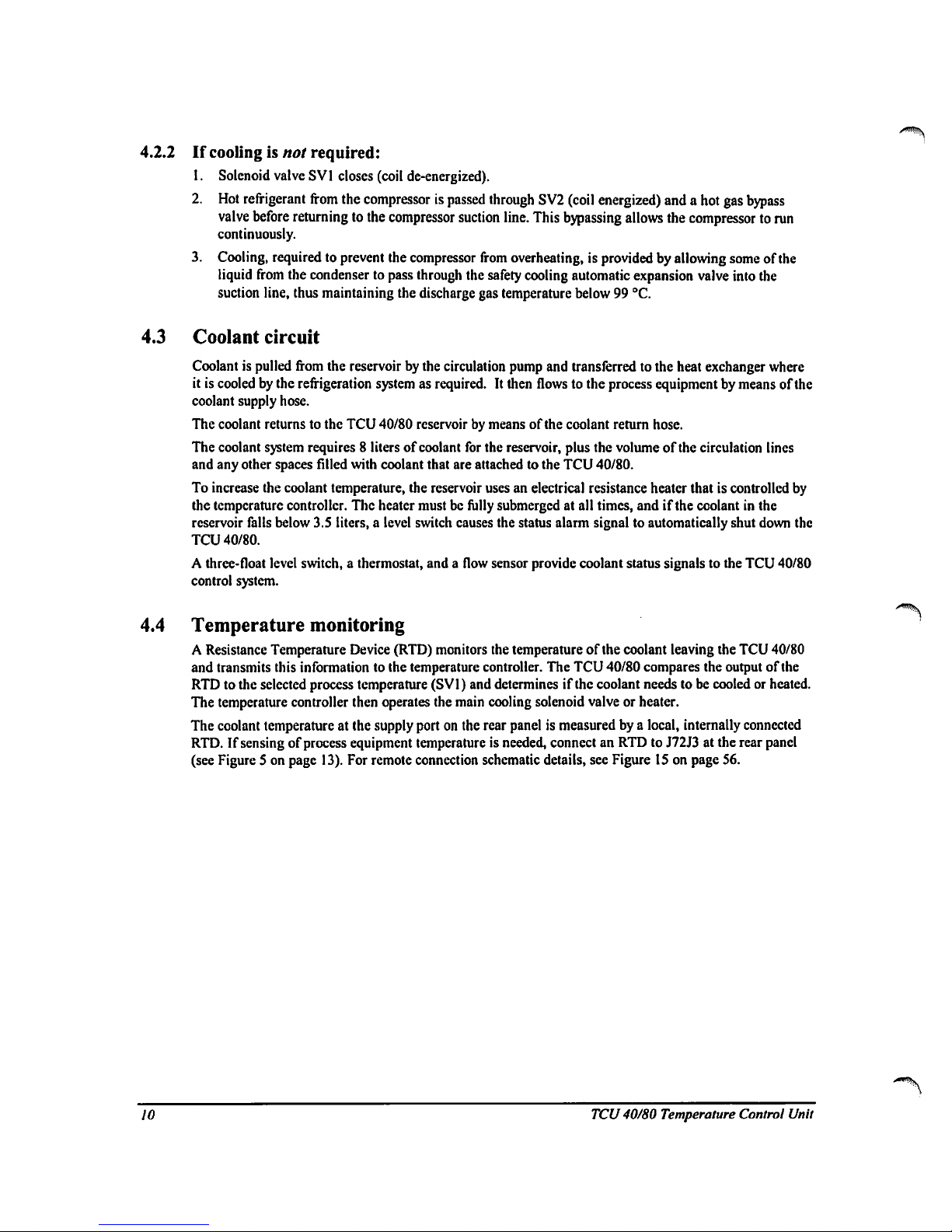
4.5
Front
panel
Figure
4 shows
the
Front
Panel.
Table4,Table5and
Table6identify
its
controls
and
indicators.
|MO<
?
5
>
mat
mu
0
aw-"
Figure4-
Front panel
Table4-
Front panel
controls
Control
name
POWER
ON
RESET
EMERGENCY
OFF
START/STOP
ALARM
MUTE
Description
Lights
green
when
powerisbeing
suppliedtothe
TCU
40/80.
Resets
alarms
and
makes
the
TCU
40/80
readytooperate.
The
white
light
indicates
that
the
TCU
40/80isreadytooperate.
Removes
power
from
all
TCU
40/80
circuits
except
the
EMERGENCY
OFF
circuit.Toshut
off
power,
push
EMERGENCY
OFF
(EMO).Toreset,
rotate
the
EMERGENCY
OFF
button
clockwiseasshownonthe
switch.
Starts
and
stops
the
operationofthe
TCU
40/80.
Emitsahigh
pitched
sound
when
thereisa
fault
condition
which
has
caused
the
TCU
40/80tostop operation.
Silences
the
audible
alarm.
TCU
40/80
Temperature
Control
Unit
II
Page 18
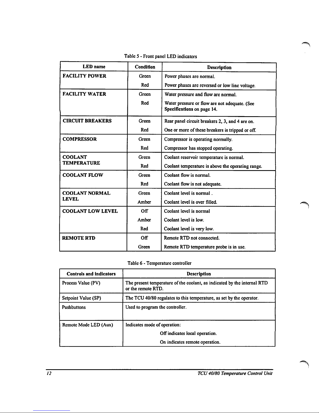
Table5-
Front
panel
LED
indicators
LED
name
FACILITY
POWER
FACILITY
WATER
CIRCUIT
BREAKERS
COMPRESSOR
COOLANT
TEMPERATURE
COOLANT
FLOW
COOLANT
NORMAL
LEVEL
COOLANT
LOW
LEVEL
REMOTE
RTD
Condition
Green
Red
Green
Red
Green
Red
Green
Red
Green
Red
Green
Red
Green
Amber
Off
Amber
Red
Off
Green
Description
Power
phases
are
normal.
Power
phases
are
reversedorlow
line
voltage.
Water
pressure
and
flow
are
normal.
Water
pressureorflow
are
not
adequate.
(See
Specifications
on page
14.
Rear
panel
circuit
breakers
2, 3,
and4are
on.
Oneormoreofthese
breakersistrippedoroff.
Compressorisoperating
normally.
Compressor
has
stopped
operating.
Coolant
reservoir
temperature
is
normal.
Coolant
temperature
is
above
the
operating
range.
Coolant
flowisnormal.
Coolant
flowisnot
adequate.
Coolant
levelisnormal.
Coolant
levelisover
filled.
Coolant
levelisnormal
Coolant
levelislow.
Coolant
levelisvery
low.
Remote
RTD
not
connected.
Remote
RTD
temperature
probeisin
use.
Table6-
Temperature
controller
Controls
and
indicators
Process
Value
(PV)
Setpoint
Value
(SP)
Pushbuttons
Remote
Mode
LED
(Aux)
Description
The
present
temperature
of
the
coolant,asindicatedbythe
internal
RTD
or
the
remote
RTD.
The
TCU
40/80
regulates
to this
temperature,
as
setbythe
operator.
Usedtoprogram
the
controller.
Indicates
modeofoperation:
Off
indicates
local
operation.
On
indicates
remote
operation.
12
TCU
40/80
Temperature
Control
Unit
Page 19
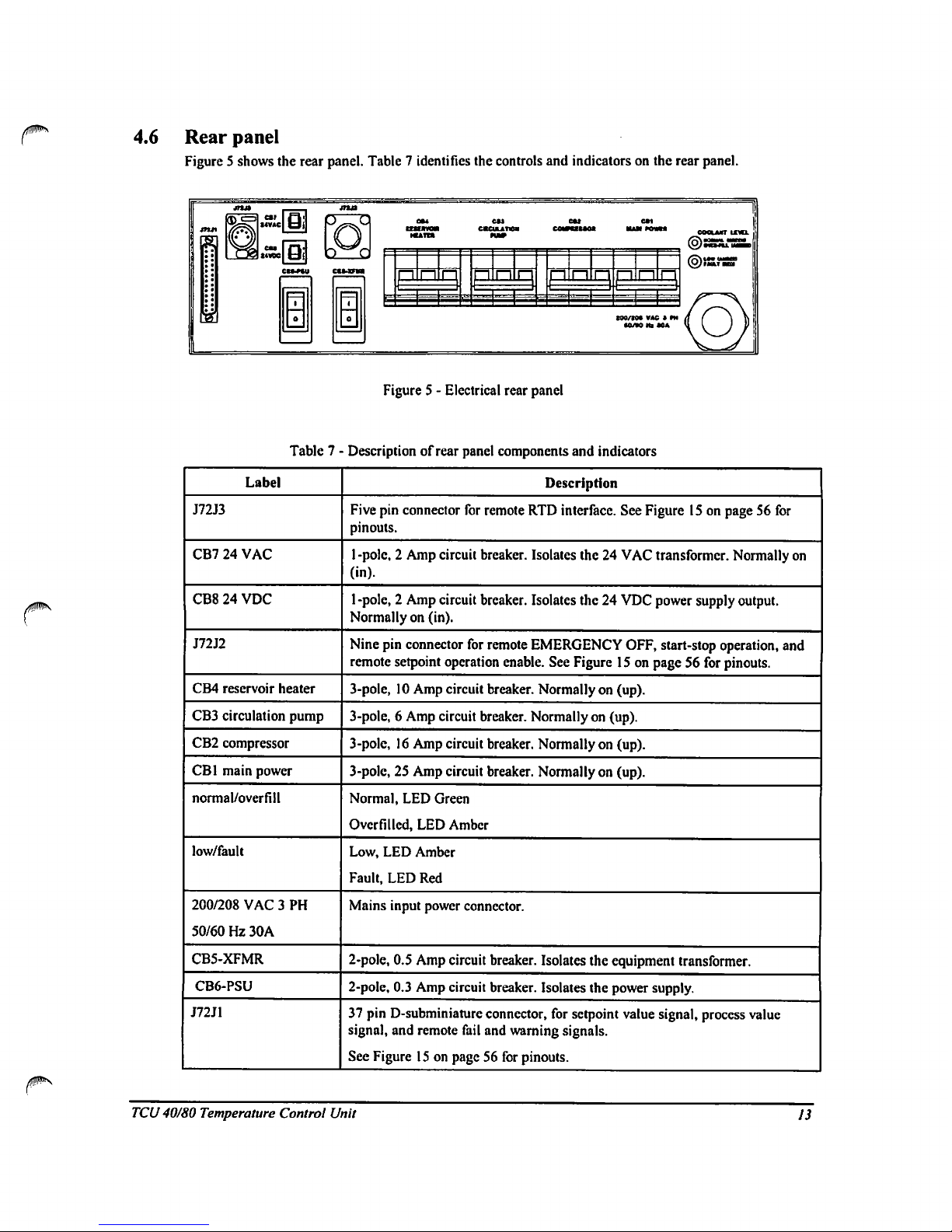
4.6
Rear
panel
Figure5shows
the
rear
panel.
Table7identifies
the
controls
and
indicators
on
the
rear
panel.
D
G
t
Fj
cocuurr
iml
p
n
n
pi
n
p!
=
H
t90/t0*
VAC
» *M
•0/WHi*0A
Figure5-
Electrical
rear
panel
Table7■
Label
J72J3
CB724VAC
CB824VDC
J72J2
CB4
reservoir
heater
CB3
circulation
pump
CB2
compressor
CB1
main
power
normal/overfill
low/fault
200/208
VAC3PH
50/60Hz30A
CB5-XFMR
CB6-PSU
J72J1
■
Description
of
rear
panel
components
and
indicators
Description
Five
pin
connector
for
remote
RTD
interface.
See
Figure15on
page56for
pinouts.
1
-pole,2Amp
circuit
breaker.
Isolates
the24VAC
transformer.
Normally
on
(in).
l-pole,2Amp
circuit
breaker.
Isolates
the24VDC
power
supply
output.
Normallyon(in).
Nine
pin
connector
for
remote
EMERGENCY
OFF,
start-stop
operation,
and
remote
setpoint
operation
enable.
See
Figure15on
page56for
pinouts.
3-pole,10Amp
circuit
breaker.
Normallyon(up).
3-pole,6Amp
circuit
breaker.
Normallyon(up).
3-pole,16Amp
circuit
breaker.
Normallyon(up).
3-pole,25Amp
circuit
breaker.
Normallyon(up).
Normal,
LED
Green
Overfilled,
LED
Amber
Low,
LED
Amber
Fault,
LED
Red
Mains
input
power
connector.
2-pole,
0.5
Amp
circuit
breaker.
Isolates
the
equipment
transformer.
2-poIe,
0.3
Amp
circuit
breaker.
Isolates
the
power
supply.
37
pin
D-subminiature
connector,
for
setpoint
value
signal,
process
value
signal,
and
remote
fail
and
warning
signals.
See
Figure15on
page56for
pinouts.
TCU
40/80
Temperature
Control
Unit
13
Page 20
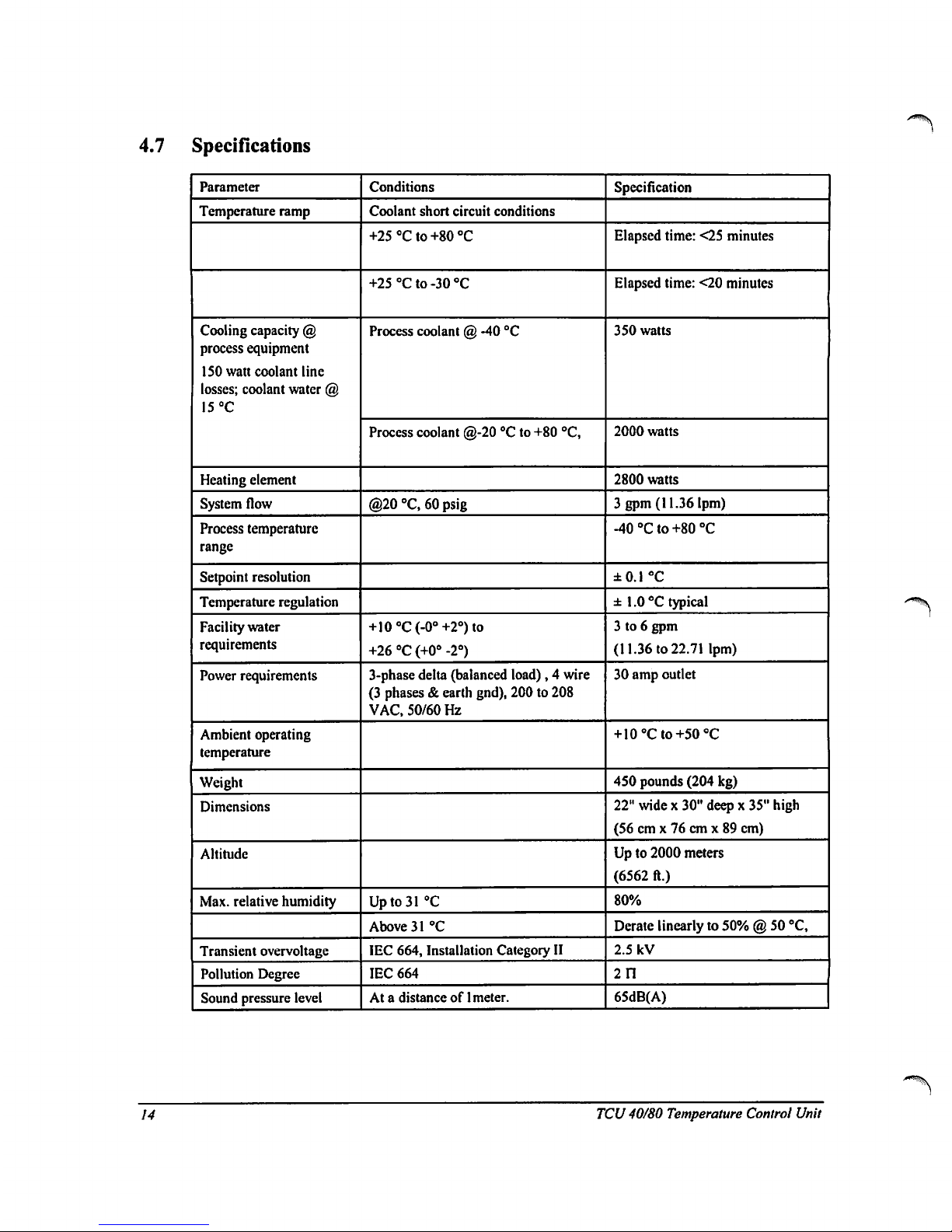
4.7
Specifications
Parameter
Temperature
ramp
Cooling
capacity
@
process
equipment
ISO
watt
coolant
line
losses;
coolant
water
@
15
°C
Heating element
System
flow
Process
temperature
range
Setpoint
resolution
Temperature
regulation
Facility
water
requirements
Power
requirements
Ambient
operating
temperature
Weight
Dimensions
Altitude
Max.
relative
humidity
Transient
overvoltage
Pollution
Degree
Sound
pressure
level
Conditions
Coolant
short
circuit
conditions
+25°Cto+80°C
+25°Cto-30°C
Process
coolant@-40
°C
Process
coolant
@-20°Cto
+80
"C,
@20
°C,60psig
+10oC(-0°+2°)to
+26"C(+0°
-2°)
3-phase
delta
(balanced
load),4wire
(3
phases&earth
gnd),
200to208
VAC,
50/60
Hz
Upto31
"C
Above31°C
IEC
664,
Installation
Category
II
IEC
664
Atadistanceof1
meter.
Specification
Elapsed
time:
<25
minutes
Elapsed
time:
<20
minutes
350
watts
2000
watts
2800
watts
3
gpm
(11.36
lpm)
-40°Cto+80°C
±0.1
°C
±
1.0°Ctypical
3to6
gpm
(11.36to22.71
lpm)
30
amp
outlet
+
10°Cto+50°C
450
pounds
(204
kg)
22"
widex30"
deepx35"
high
(56cmx76cmx89
cm)
Upto2000
meters
(6562
ft.)
80%
Derate
linearlyto50%@50
°C,
2.5
kV
211
65dB(A)
14
TCU
40/80
Temperature
Control
Unit
Page 21
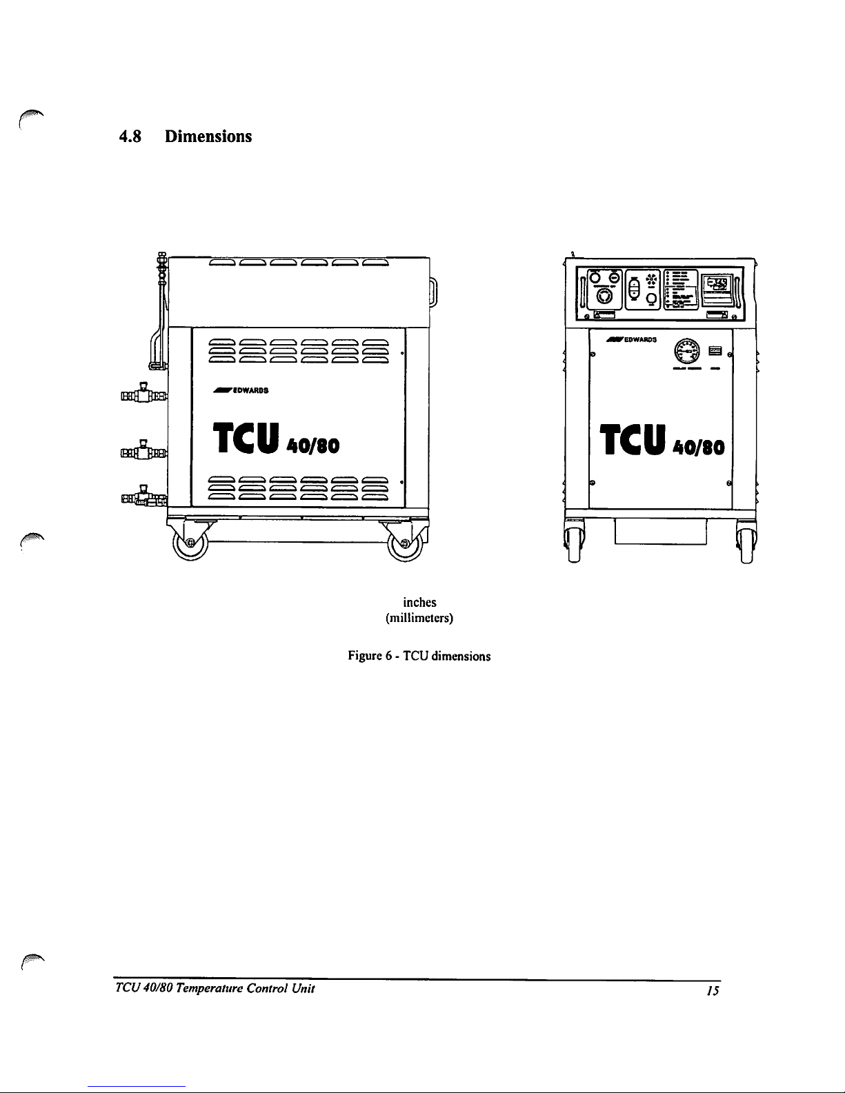
4.8
Dimensions
TCU
40/80
TCU
40/80
inches
(millimeters)
Figure6-
TCU
dimensions
TCU
40/80
Temperature
Control
Unit
15
Page 22
5
INSTALLATION
5.1
Receiving
and
unpacking
Doacomplete
visual
inspection
of
the
TCU
40/80
for
any
damage.Donot
use
the
TCU
40/80ifphysical
damageisevident.Ifthereisany
damage,
notify
your
supplier
and
the
carrierinwriting
within
three
days;
state
the
item
numberofthe
TCU
40/80
together
with
your
order
number
and
supplier's
invoice
number.
Retain
all
packing
materials
for
inspection.
Caution
When
usingaforklift
to
moveorposition
the
TCU
40/80,donot
install
the
secondary
containment
receptacle
until
the
TCU
40/80isin
position.
Failuretofollow
these
instructions
may
lead
to
damageofthe
secondary
containment
receptacle
causedbythe
forksofthe
forklift.
5.2
Location
Allowaspace
46"
widex54"
deep
for
the
TCU
40/80
cable
and
coolant
connections.
The
TCU
40/80
should
haveatleast
two
feetofclearance
at
the
rear
and
one
foot
along
the
sidesofthe
unit.Besure
that
the
mounting
surface
can
safely
support
the
weightofthe
TCU
40/80
(450
pounds
evenly
distributed).
The
centerofgravityisapproximately
the
centerofthe
refrigeration
compartment.
When
usingafork-lift
to
move
the
TCU
40/80,
position
the
forks
from
the
sideofthe
unit.
The
TCU
40/80
weighs
450
pounds
(204
kg).
Failuretotake
proper
careinmovingorlifting
these
units
can
resultinserious
bodily
injury.
A3foot
(1m)
service
lengthofthe
power
cableisrequiredtofully
open
the
electrical
drawer.
Therefore,
do
not
install
the
TCU
40/80
further
than7feet
(2.1m)from
the
power
source.
5.2.1
Securing
the
unit
The
four
lockable
castersofthe
TCU
40/80
swiveltoprovide
maximum
maneuverability.
Make
sure
that
all
four
casters
are
turned
inward
and
lockedinposition
once
Ihe
TCU
40/80issituated.
5.2.2
Installing
the
secondary
containment
receptacle
The
secondary
containment
receptacle
slides
into
the
base
from
the
rearofthe
unit.
5.2.3
Floor
levelers
An
optional
floor
leveler
kitisavailable
to
compensate
for
uneven
surfaces.
See
Table15on
page52for
ordering
information.
16
TCU
40/80
Temperature
Control
Unit
Page 23
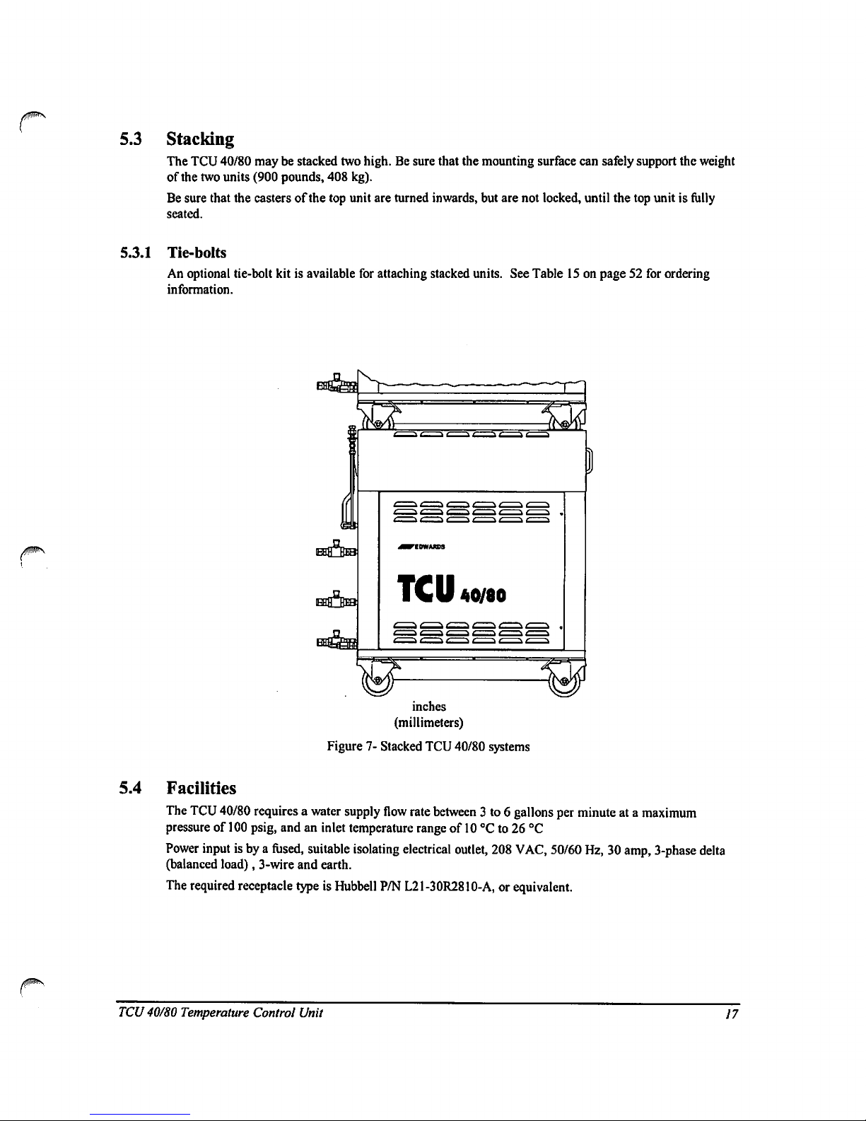
5.3
Stacking
The
TCU
40/80
maybestacked
two
high.Besure
that
the
mounting
surface
can
safely
support
the
weight
of
the
two
units
(900
pounds,
408
kg).
Be
sure
that
the
castersofthe
top
unit
are
turned
inwards,
but
are
not
locked,
until
the
top
unitisfully
seated.
5.3.1
Tie-bolts
An
optional
tie-bolt
kitisavailable
for
attaching
stacked
units.
See
Table15on
page52for
ordering
information.
TCU
40/80
inches
(millimeters)
Figure7-Stacked
TCU
40/80
systems
5.4
Facilities
The
TCU
40/80
requires
a
water
supply
flow
rate
between
3 to6gallons
per
minuteata
maximum
pressureof100
psig,
andaninlet
temperature
rangeof10°Cto26°C
Power
inputisbyafused,
suitable
isolating
electrical
outlet,
208
VAC,
50/60
Hz,30amp,
3-phase
delta
(balanced
load),
3-wire
and
earth.
The
required
receptacle
typeisHubbell
P/N
L21-30R2810-A,
or
equivalent.
TCU
40/80
Temperature
Control
Unit
17
Page 24

5.4.1
Water
and
coolant
connections
Figure8showsarear
viewofthe
TCU
40/80
with
its
water
and
coolant
connections.
inches
(millimeters)
Figure8-System
rear
view
18
j
TCU
40/80
Temperature
Control
Unit
Page 25

5.4.2
Water
/JWN
Connections
to
the
water
supply
and
return
are
madetoeither
Vi"
brass
barb
fittingsorVi"
compression
fittings.
For
bare
hose
connections
("A"
nominal
I.D.):
1.
Slip
the
hose
over
the
barb
fitting
and
tighten
the
hose
clamp.
2.
Turnonthe
water
supply
and
check
for
leaks.
For
connections
using
hose
with
tube
adaptersortubing
('/i"
nominal
O.D.):
1.
Remove
the
adapter
coupledtothe
hose
barb.
2.
Insert
the
tube
adapterortubing
with
the
appropriate
ferrule
and
compression
nut.
3.
Tighten
the
compression
nut,
turnonthe
water
supply,
and
check
for
leaks.
Rear
Acctii
Pantl
F»rrulo
•
1/2'
Compr.jslon
Nut
•
1/2"
O.O.
Tubing
or
Hose
Tuba
Adaptor
Supplied
Adaptor
With
Hoie
Barb
♦NOT
INCLUDED
Figure 9
Water
connections
5.4.3
Coolant
Note:Ifthis
TCU
40/80isbeing
installed
on
process
equipment
that
has
been used
mthacoolant
other
than
Fluorinert.
contact
process
equipment
supplier
for
retrofit
instructions.
Connections
to
the
coolant
supply
and
return
are
madeonthe
rear
panel
(see
Figure8on
page
18).
The
maximum
distance
between
the
process
equipment
and
the
TCU
40/80is50
feet
(100
feet
total
hose
length).
1.
Attach
the
hosestothe
supply
and
return
compression
fittings.
Follow
the
hose
manufacturers
recommendations
for
appropriate
adapters.
2.
Insulate
the
hoses
with
closed
cell
insulation
in
ordertominimize
heat
loss.
3.
Tape
and
glue
the
insulated
jointstoavoid
condensation
and
icing.
5.4.4
Remote
connections
Wiring
details
for
remote
connections
are
showninFigure15on
page
56.
Remote
connections
should
not
be
run nearorparalleltoa.c.
power
linesorin
the
vicinity
of
equipment
that
generates
large
electric
fields.
TCU
40/80
Temperature
Control
Unit
19
Page 26

6
OPERATION
6.1
Preparation
Verify
that
water
and
coolant
connections
are
madeatboth
ends,
that
the
drain
valveisclosed
and
the
coolant
supply
and
return
valves
are
open.
Connect
the
remote
interfaces
if
required.
1.Touseanexternal
RTD
probe,
attachitto
connector
J72J3.
RefertoFigure15on
page
56.
Verify
that
the
plug
J72J2isinstalled.
2.
Press
the
EMERGENCY
OFF
buttononthe
front
panel.
3.
Plug
the
TCU
40/80
power
cord
intoafused,
switchable,
30
amp,
3-phase,
208
VAC
outlet.
4.
Ensure
that
all
circuit
breakersonthe
rear
panel
areintheONposition.
CB7
and
CB8
are
non-
switchable
circuit
breakers
and
will
trip
when
thereisa
problem.
They
cannotbeturnedonor
off,
but
they
are
re-settablc.
6.2
Poweringupthe
TCU
40/80
1.
Verify
that
the
POWERONlamponthe
front
panelisilluminated.
2.
Release
the
EMERGENCY
OFF
button.
If
the
Facility
Power
LED
illuminates,
the
line
voltageislow,
or the
phaseofthe
main
power
supplyisreversed.
Adjust
the
line
voltage,ifitislow.
Correct
the
phasesbyswapping
two
phasesinthe
electrical
outlet.
3.
Press
the
RESET
button
and
verify
the
front
panel
indicators
are asinthe
Reset
Condition
column
of
Table
8.
Table8-
Front
panel
power up
indicator
conditions
Indicator
POWER
ON
RESET
FACILITY
POWER
FACILITY
WATER
CIRCUIT
BREAKERS
COMPRESSOR
TEMPERATURE
FLOW
NORMAL
LEVEL
LOW
LEVEL
REMOTE
RTD
(if
used)
Reset
condition
Green
Off
Green
Green
Green
Off
Green
Off
Off
Red
Green
Start
condition
Green
White
Green
Green
Green
Green
Green
Green
Green
Off
Green
20
TCU
40/80
Temperature
Control
Unit
Page 27

4.
Press
MUTEtosilence
the
alarm.
The
TCU
40/80isshipped
without
coolant.
The
coolant
level
alarm
will
sound
and
the
front
panel
Reservoir
Coolant
Low
Level
LED
willbered
indicating
that
the
reservoir
mustbefilled.
5.
Fill
the
coolant
reservoir
using
the
procedure
Filling
the
Reservoir
on page
26.
6.
Press
the
START
button
and
verify
the
front
panel
indicators
areasin
the
Start
Condition
column
of
Table
8.
7.
Useahalogen
leak detectortocheck
all
supply
and
return
line
connections
at
both
the
TCU
and
process
equipment,
around
the
pump
head
assembly,
drain
valve,
heater,
flow
switch,
vent
line,
fill
line,
and
reservoir
pressure
relief
valve.
6.3
Changing
the
setpoint
value
(SV1)
The
following
instructions
are
for
local
temperature
control
only.
Do
not
exceed
the
temperature
range
of-40°Cto
+80
Thisisthe
normal
operating
rangeofthe
TCU
40/80.
To
change
the
temperature
settings
press
pageupor
page
downtocither
increaseordecrease
the
temperature.
The
red
display
"PV"
indicates
the
process
value.
The
green
display
"SP"
indicates
the
current
setpoint.
Note:
The
temperature
controller
has
been
programmedtoprevent
the
setpoint
from
exceeding
the
normal
operating
rangeofthe
TCU
40/80.
The
controller
is
also
protected
from
unauthorized
changes
to
the
Pid
and
other
settings,
Contact
the
process
equipment
supplier
for
accesstothese
settings
and
other
information.
'P
EDWARDS
0UT1O
OUT
tO
OUH.
F-j-71
-■
HUBI
MB
4
:
mb
Figure10-
Temperature
controller
6.4
Temperature
controller
Pid
settings
Edwards
default
settings
are:
PID1-heating
Pbl
Arl
rAtl
dbl
value
8.0
0.43
7.0
1.0
PID2-cooling
Pb2
Ar2
rAt2
db2
value
12.5
0.7
9.0
1.0
parameter
proportional
band
automatic
reset
rate
deadband
TCU
40/80
Temperature
Control
Unit
21
Page 28

6.5
Remote
set-point
To
use
the
remote
set-point,
wire
the
J72J2
mating
connectorasillustrated
on
page
56.
24vac
mustbeappliedtopins3and
4.
The
AUX
LEDonthe
temperature
controller
will
illuminate
indicating
remote
setpoint
enable
mode
as
soonasthe
mating
connectorisinstalled.
6.6
Flow
rate
adjustment
Caution
Do
not
exceed
coolant
pressureof100
psi.
Exceeding
the
coolant
pressure
may
resultindamage
to
the
pump.
The
Fluorinert
flow
rateofthe
TCU
40/80isfactory
settoprovide
approximately
3
gpmat60
psig/20°C
foraunit
operatingat208vac/3-ph/60Hz.
If
the
flow
rate
requires
adjustmenttoaccommodate
the
process
equipment
suppliers
recommendations,
follow
the
steps
below.
The
flow
rate
maybemeasured
usingaflow
meter
externaltothe
TCU
40/80.
1.
Open
the
left
side
access
door.
2.
Peel
back
the
insulation
covering
the
by-pass
valve.
RefertoFigure1on
page
6.
3.
The
valve
handle
canbefoundinthe
plastic
bag
securedtothe
pump.
Reduce
the
flowbyturning
the
valve
stem
clockwise.Toincrease
the
flow,
turn
the
stem
counter
clockwise.
The
valveisa
1/4
turn
valve.
4.
Once
the
required
flow
rate
has
been
achieved,
return
the
valve
handletothe
bag
for
future
use,
glue
the
insulation
backinplace,
and
secure
the
access
door.
22
TCU40/80
Temperature
Control
Unit
Page 29

7
MAINTENANCE
This
section
contains
information
that
will
allow
youtosafely
keep
your
TCU
40/80inworking
order.
It
contains
important
Hazard
Warnings,aPreventive
Maintenance
Scheduleonpage
27,
and
a
Troubleshooting
Guideonpage
41.
Maintenance
to
the
electrical
systemofthe
TCU40/80
shouldbeperformedbyqualified
personnel
only.
Warning
The
refrigeration
units
are
scaled
and
are
not
user
serviceable.
Only
trained
and
licensed
refrigeration
personnel
should
perform
repairs
on
this
equipment.
All
applicable
EPA
regulations
apply.
7.1
Hazard
warnings
High
Pressure
Water and
the
coolant
arc
pressurized
within
this
equipment.
Water
pressure
will
depend
upon
utility
supply,
but
usuallyisupto60
psig.
The
coolant
canbeat
pressuresupto
100
psig.
Refrigerant
pressures
canbeupto300
psig.
Do
not
open
lines
with
pressure
present.
Toxic
Gases
The
coolant
breaks
down
above
215
°C.Ifthe
coolantisallowedtoreach
these
temperatures,
toxic
gasses
maybedischarged
from
the
unit.
Refertothe
Appendix
for
Material
Safety
Data
Sheets
for
the
coolant
and
refrigerant
usedinthis
system.
High
Pressure
The
reservoir
may
become
pressurized
due
to
changesintemperature.
Undernocircumstances
should
the
reservoir
pressure
relief
valveberemovedorcapped
off.
TCU
40/80
Temperature
Control
Unit
23
Page 30

High
Pressure
The
refrigerant
lines
areathigh
pressure.
Undernocircumstances
should
the
refrigerant
pressure
relief
valveberemovedorcapped
off.
Eye
Protection
Hand
Protection
Leakageorfailureofhigh
pressure
circuits
may
cause
injuryorirritation
of
the
eyes.
Eye
protection
shouldbeworn
when
working
with
fluid
systems.
Hotorcold
fluids
and
surfaces
can
cause
injury or
irritation
of
the
hands.
Hand
protection
shouldbeworn
when
working
with
these
fluid
systems.
Electric
Shock
Ensure
that
all
electrical
power
has
been
removed
and
the
main
circuit
breaker
has
been
turned
off
priortoopening
the
electrical
drawer.
The
EMERGENCY
OFF
circuit
(EMO)
does
not
disconnect
all
power
from
the
electrical
drawer.
Extreme
caution
mustbeobservedifperforming
maintenance
operations
with
the
drawer
open.
Hot
Surface
Refrigeration
and
circulating
fluid lines
can
attain
temperatures
as
highas110
°C.
Caution
mustbeobserved.
24
TCU
40/80
Temperature
Control
Unit
Page 31

7.2
Hazards
Table9gives
the
classifications
of
electrical
hazards.
This
number
indicates
the
severityofthe
hazard
as
definedbySEMI
S2-93.
Table9-
Electrical
hazards
classifications
Classification
Typel
Type
2
Type
3
Type
4
Type
5
Description
Equipmentisfully
de-energized.
Equipmentisenergized.
Live
circuits
are
covered
or
insulated.
Workisperformedata
remote
location
to
preclude
accidental
shock.
Equipmentisenergized.
Live
circuits
are
exposed
and
accidental
contactispossible.
Potential
exposures
are
less
than30volts
RMS,
42.2
volts
peak,
240
volt-amps,
20
Joules.
(See
NFPA
79-14.3,
IEC
204,UL1950&1262,
IEC
950.)
Equipmentisenergized.
Live
circuits
are
exposed
and
accidental
contactispossible.
Potential
exposures
are
greater
than30volts
RMS,
42.2
volts
peak,
240
volt-amps,
20
Joulesorradio
frequency
(rf)ispresent.
Equipmentisenergized
and
measurements
and
adjustments
require
physical
entry
into
the
equipment,
or
equipment
configuration
will
not
allow
the
useofclamp-on
probes.
Comment
None
called
out.
None
called
out.
Called
out as
Type
3.
Called
outasType
4.
None
called
out.
TCU
40/80
Temperature
Control
Unit
25
Page 32

7.3
Filling
the
reservoir
Warning
When
retrofitting
a
TCU
40/80inplaceofa
water/glycol
unit,
the
coolant
lines
mustbeflushed
with
nitrogentoremove
moisture
prior
to
installation.
1.
Open
the
vent
port
valve
(see
Figure8on
page
18)toavoid
air
locks
that
may
slow
filling.
2.
Remove
the
plug
and
fasten
the
funnel
accessory
to
the
Vi"
fill
port
locatedatthe
rearofthe
unit (see
Figure8on
page
18).
3.
Fill
the
reservoir
with
Fluorinert
heat
transfer
fluid.
The
amount
needed
foranew
installation
is
approximately
44
pounds
for
the
TCU
andanadditional
amount
for
process
lines
(approx.
.15
lbs/ft.;
1/2"
tube)
and
other
external
volumes.
Fill
the
reservoir
until
the
Coolant
Normal
Level
LEDonthe
rear
electrical
panel
turns
green.
4.Inthe
eventofover-filling,
the
Coolant
Normal
LED
will
change
from
greentoamber.
Drain
excess
fluid
until
the
Coolant
Normal
Level
LED
turns
green.
RefertoDraining/Bleeding
the
Coolant
Reservoir,
below.
7.4
Draining/bleeding
the
coolant
reservoir
It
maybenecessarytodrain
the
coolant
reservoir
for
storageofthe
TCU
40/80orduetomoisture
contamination
of
the
coolant.
v
It
maybenecessarytobleed
the
coolant
reservoir
to
correctanoverfill
condition.
Note:
The
unit
may
continue
running
during
this
procedure.
Follow
the
procedure
below
wheneveritbecomes
necessarytodrainorbleed
the
system.
Firtreme
Temnerature
Hot
or
cold
coolant
may
reach
"40
°C
t0
+80
°C
during
UXtreme1emperature
operation.
Hot
or
cold
fluid
can
cause
burns.
Coolant
shouldbeat
ambient
temperature
before
handling.
1.
Open
the
vent
valve
locatedatthe
topofthe
unit.
2.
Placeanappropriate
container
beneath
the
drain
valve.
The
capacityofthe container
used
needstobe
10
liters
plus
the
volumeofthe
hoses
and
the
volumeofthe
process
equipment.
3.
Remove
the
cap
fitting
from
the
endofthe
drain
valve.
4.
Open
the
reservoir
drain
valve.
5a.Tocorrectanoverfill
condition,
drain
the
reservoir
until
the
Coolant
Level
Normal
LEDonthe
rear
electrical
panel
turns
green.
Close
the
reservoir
drain
and
vent
valves
when
the
LED
turns
green.
5b.Toempty
the
reservoir,
remove
powertothe
TCU
and
allow
the
unittodrain
until
all
coolant
has
been
removed.
6.
Close
the
reservoir
drain
and
vent
valves.
7.
For
proper
disposalofthe
coolant,
follow
the
manufacturers
recommendations.
Note:
Uncontaminated
Fluorinert
maybereused.
The
Fluorinert
shouldbestoredina
compatible
and
sealed
container.
26
TCU
40/80
Temperature
Control
Unit
Page 33

7.5
Temperature
probe
calibration
The
Edwards
Temperature
Controller
comes
equipped
withafactory
calibrated
internal
+10V
remote
input/output
option
making
calibration
unnecessary.
7.6
Preventive
maintenance
schedule
Table10shows
the
maintenance
requiredtokeep
the
TCU
40/80ingood
working
order.
Failuretofollow
this
schedule
may
resultindegradationofsystem
performance.
Table10-
Preventive
maintenance
schedule
Frequency
Semi
annual
ly
Annually
Operation
Verify
system
status
Check
coolant
level
Check
lamps
Coolant
leak
check
Refrigeration
leak
check
Insulation
repair
Water
leak
check
Replace
solenoid
coils
SV1
and
SV2
System
check
Lamp
replacement
Hazard
(Type
3)
(Type
3)
(Type
3)
(Type
3)
(Type
3)
(Type
3)
(Type
3)
(Type
3)
Note:
All
maintenance
should be
recordedonthe
Preventative
Maintenance
Record
label
locatedonthe
insideofthe
left-hand
side
access
panel.
TCU
40/80
Temperature
Control
Unit
27
Page 34

1
7.7
Semi-annual
preventative
maintenance
Refertothe
Troubleshooting
sectiononpage42when
results
for
anyofthe
following
checkpoints
are
notasexpected.
7.7.1
Required
equipment
•
12"
slotted
screwdriver
•
Spare
lamps
(24
vac/60
mA)
•4"slotted
screwdriver
•
Fluorinert
•
Two
10"
adjustable
wrenches•Insulation
Tape
•
Halogen
leak
detector
7.7.2
Preparation
•
Locate
the
two
screws
securing
eachofthe
side
access
panels
and
loosentoopen
doors.
•
Listen
for
excessiveorquestionable
noiseorsounds
coming
from
the
pump
assembly, motor,
compressor,orsolenoid
valves
(SV1
and
SV2).
7.7.3
Verify
system
status
•
Verify
system
status
led
indicators
on
the
front
electrical
panel.
(See-Front
panel
power
up
indicator
conditions
tableonpage
20.)
7.7.4
Refrigeration
leak
check
•
Visually
check
for
signsofcompressor
oilonthe
base,
insulation,
andonall
refrigeration
pipework.
•
Usingahalogen
leak
detector
check around
the
discharge
and
suction
service
valvesofthe
compressor,
and
all
accessible
refrigeration
pipework.
7.7.5
Fluorinert
leak
check
•
Useahalogen
leak
detectortocheck
all
supply
and
return
line
connections
at
both
the
TCU
and
process
equipment,
around
the
pump
head
assembly,
drain
valve,
heater,
flow
switch,
vent
line,
fill
line,
and
reservoir
pressure
relief
valve.
7.7.6
Water
leak
check
•
Visually
check
for
signsofwater
leaksatall
water
line
connections
externaltothe
TCU
andatthe
condenser
connections
inside
the
unit.
7.7.7
Insulation
repair
Note:Ifice
formationisexcessive,
it
maybenecessarytocorrect
this
condition
before
insulation
can
be
repaired.
•
Visually
inspect
refrigeration
and
process
fluid
lines
both
inside
the
TCU
cabinet
andatthe
supply
and
return
line
connections
for
signsofice
formation.
Correct
insulation
as
necessary.
28
TCU
40/80 Temperature
Control
Unit
Page 35

7.7.8
Lamp
check/replacement
Electric
Shock
Ensure
all
electrical
power
has
been
removed
and
the
main
circuit
breaker
has
been
turned
off
due
to
the
presenceofhigh
voltageorcurrent.
Caution
Shouldalamp
require
replacement,
notify
the
appropriate
personnel
thatanEMO
condition
will
occur.
Failuretofollow
these
instructions
may
result
in
the
shut-downofthe
process
tool
and
associated
equipment.
Visually
verify
that
the
POWERONand
RESET
lamps
are
working.
If either
lamp
needs
replacement
and
the
proper
authorization
has
been
obtained:
1.
Press
STOP.
2.
Turn
off
the
main
circuit
breaker
(CB1).
3.
Disconnect
power
cord
from
mains
power
supply.
4.
Locate
the
two
securing
screwsonthe
front
electrical
panel
and
loosen.Open
the
electrical
drawer.
5.Ifreplacing
the
POWERONlamp,
locate
contactor
block
(LPl)onthe
back
sideofthe
front
electrical
panel.Ifreplacing
the
RESET
lamp,
locate
contactor
block
(PBl)onthe
back
sideofthe
front
electrical
panel.
6.
Pryupthe
metal
retaining
ring attachedtothe
coupling
plate.
Remove
the
contact
block
assembly.
7.
Replace
the
defective
lamp.
8.
Reinstall
the
contact
block
assemblybysnappingitback
onto
the
front
clement.
9.
Close
the
electrical
drawer
and
tighten
securing
screws.
10.
Reconnect
mains
power
and
turnonthe
main
circuit
breaker
(CBI)..
The
POWERONlamp
should
be
illuminated.
11.
Press
RESET.
The
lamp
should
illuminate.
Press
STARTtoreactivate
the
TCU.
Figure11-
Lamp
replacement
TCU40/80
Temperature
Control
Unit
29
Page 36

7.8
Annual
preventative
maintenance
Refertothe
Troubleshooting
sectiononpage42when
results
for
anyofthe
following
check
points
are
notasexpected.
7.8.1
Required
equipment
12"
slotted
screwdriver
4"
slotted
screwdriver
7"
slotted
screwdriver
8"
phillips
screwdriver
Two
10"
adjustable
wrenches
Wire
strippers
(14
AWG)
Two
test
clips
w/12"
leads
Miniature
diagonal
cutters
Halogen
leak
detector
3\8"
open-ended
wrench
1\4"
open-ended
wrench
Wire
crimpers-Insulated
terminal
Digital
multimeter
(DMM)
Remote
RTD
connector
plug
(J72J3)
7.8.2
Required
supplies
•
Preventative
Maintenance
Kit
(P60153005)
•
Fluorinert
•
Insulation
Tape
7.8.3
Solenoid
valve
coil
replacement
Electric
Shock
Ensure
all
electrical
power
has
been
removed
and
the
main
circuit
breaker
has
been
turned
off
due
to
the
presence
of high
voltageorcurrent.
Caution
Shouldasolenoid
valve
coil
require
replacement,
notify
the
appropriate
personnel
thatanEMO
condition
will
occur.
Failuretofollow
these
instructions
may
result
in
the
shut-downofthe
process
tool
and
associated
equipment.
30
1.
Press
STOP..
Turn
off the
main
circuit
breaker
(CB1).
2.
Disconnect
the
power
cord
from
the
mains power
supply.
3.
Locate
the
main
cooling
solenoid
valve
(SV1)
from
the
left
side
access
door.
4.
Remove
the
junction
box
attachment
screw.
Slide
off the
junction
box
cover.
5.
Back
off the
strain relief
retaining
nut.
6.
Unfasten
the
ground
screw.
Cut
off the
wire
butt
splices
(ensuring
that
the
wire
labels
remain
attachedtothe
base
assembly)
and
pull
the
wires
through
the
junction
box.
7.
Remove
the
solenoid
valve
coil
lock
nut.
Lift
off
the
spacer
cup.
Separate
the
coil
from
the
solenoid
valve
bodybygently
pullingupon
the
coil.
8.
Remove
replacement
solenoid
valve
coil
from
packaging.
9.
Remove
the
junction
box.
10.
Note
the
locationofthe
conduit
holeonthe
coil
removed
and
remove
the
appropriate
"knock-out"
on
the
replacement
coil.
TCU
40/80 Temperature
Control
Unit
Page 37

11.
Gently
slip
the
replacement
coil
onto
enclosing
tubeofsolenoid
valve
body.
12.
Pull
the
base
assembly
wiring
through
conduit
hole
and
sliponthe
strain
relief
retaining
nut.
13.
Attach
the
ground
wiretocoil.
14.
Strip
the
endsofall
wiresonbase
assembly
and
solenoid
valve
coils.
15.
Crimponthe
butt
wire
splices.
16.
Tighten
the
strain relief
retaining
nut.
17.
Install
the
original
junction
box
cover
and
fasten
attachment
screw.
18.
Install
the
spacer
cup.
19.
Install
and
tighten
the
lock
nut.
20.
Verify
the
coil
junction
boxislabeled
SV1.
21.
Repeat
the
procedure
for
Hot
Gas
Bypass
solenoid
valve
coil
(SV2).
22.
Discard
the old
solenoid
coils.
23.
Perform
the
System
Check
procedure.
Retaining
nut
Junction
box
cover
Ground
screw
Lock
nut
Spacer
cup
Figure 12-Solenoid
coil
replacement
TCU
40/80
Temperature
Control
Unit
31
Page 38

7.8.4
System
check
Component
settings
Motor
overload
setting
(K3)
Current sensing
relay
setting
(CSR)
Thermostat
setting
(TS1)
High
pressure
switch
setting
(PS1)
3.S
amps
25
amps
210°F
(Differential
setat10°F)
300
psig.
(Differential
setat40
psig)
Power-up
conditions
•
Power
cord
connectedtomains power
supply.
•
All
circuit
breakers
on.
•
EMO
released.
•
Drawer
interlock
switchinmaintenance
position.
•
Host
connector
J72J2
installed
(pins5&6shorted).
•
READY
lamp
on.
Indicator
Relays
LEDs
Power
Reset
PMR
Current
sensing
relay
Condition
All
off
All
off
On
Off
Green
Off
Note:
REMOTE
RTDisoptional.
LED
willbegreenifused.
Reset
button
1.
Press
RESET.
2.
Verify
contactorKlengages.
3.
Verify
LED
indicatoronPMRisgreen.
\
Indicator
Relays
LEDs
Power
Reset
PMR
Current
sensing
relay
Condition
CR4on
all
others
off
FACILTITY
POWER,
FACILITY
WATER,
CIRCUIT
BREAKERS,
COOLANT
TEMPERATURE,
COOLANT
NORMAL
LEVEL,
green
COMPRESSOR,
COOLANT
FLOW,,
COOLANT
LOW
LEVEL,
REMOTE
RTD
off
On
On
Green
Off
Note:
REMOTE
RTDisoptional.
LED
willbegreenifused.
32
TCU
40/80 Temperature
Control
Unit
Page 39

Temperature
controller
1.
2.
All
control
parameters
and
selections
procedures
for
the
temperature
controller
are
accomplished
through
simple
MENU
selections.
These
MENU
selections
are
organized
into
PAGES.Oneach
page
you
will
findaspecific
setofrelated
functions.
The
PAGES
setup
structureisas
follows:diSP
PAGE,
Ctrl
PAGE,
inPt
PAGE, ScAL
PAGE,
Outl
PAGE
and Out2
PAGE.
To
selectaPAGE
:
Press
and
hold
the
RESET
key,
while
pressing
the^otW
keys.
The
upper
display
of
the
temperature
controller
will
incrementordecrement
through
the
PAGEs,
and
PAGE
willbedisplayed
in
the
lower
display.
To
selectaMENU
:
After
reaching
the
correct
page,
press
resettomove
through
MENUs.
The
alpha cue
for
the
MENU
will
appearonthe
upper
display
and
the
current
value
will
appearinthe
lower
display.
To
changeaMENU
value
:
After
the
MENUisselected
and
displayed,
use
the^
and*Vkeystochange
the
value.
To
enter
the
SetUp
Mode,
press
the
controller
RESET
key
and
holditfor
about3seconds.
The
controller
will
display
LocH
XXX
where
XXXisthe
security
code.
The
security
code
number
should
be
458.Ifnot,
press
either
the
JLot^
keys
until
the
display
reads
458.
Thisisthe
first
menuinthe
Ctrl
PAGE.
Verify
that
the
menu
settings
for
the
Ctrl
PAGE
are as follows
:
PID1
-heatinR
Pbl
Arl
rAtl
dbl
value
8.0
0.43
7.0
1.0
PID2-cooling
Pb2
Ar2
rAt2
db2
value
12.5
0.7
9.0
1.0
parameter
proportional
band
automatic
reset
rate
deadband
OFst
=
CooL
=
0.0FL=
=
PID2
On
Orng
rSP
=
=
0.0OnLooP
Enti
=
=
OFF
rSP
Auto=4
Au=none
rrAt
Aout
=
OFF
=
Proc
Cont
rSEn
=
HtCI
=
OFF
4.
Select
the
next
page
whichisthe
InPT
PAGE.
Verify
that
the
menu
settings
for
the
InPt
PAGE
are
as
follows:
I
SEnS=rtdt
unit=°C
CoFF=.01SPLL =
-40.0|SPUL=80.0
5.
Select
the
next
page
whichisthe
ScAL
PAGE.
Verify
that
the
menu
settings
for
the
ScAL
PAGE
areasfollows:
DP=
1
rSPH
=
AinL
=
100.0
-50.0
AinH
=
100.0
AotL
=
-100.0
AotH=100.0
rSPL=-
100.0
6.
Select
the
next
page
whichisthe
Outl
PAGE.
Verify
that
the
menu
settings
for
the
Outl
PAGE
are
as
follows:
Cycl=16
OL1=100.0
HoFF=.0
7.
Select
the
next
page
whichisthe
Out2
PAGE.
Verify
that
the
menu
settings
for
the
Out2
PAGE
arc
as
follows:
Cyc2
=16
OL2=100.0
CoFF=.0
8.
Press
START.
To
returntoOperating
Mode,
press
and
hold
the
RESET
key
for
more
than3seconds.
The
controller
will
automatically
returntooperating
mode
after10minutesofno
pushbutton
activity.
9.
Press
START.
TCU
40/80
Temperature
Control
Unit
33
Page 40

EMO
circuit
Do
not
perform
the
EMO
circuit
check
while
the
TCUison-line
with
the
process
tool.
Failuretofollow
these
instructions
will
leadtothe
shut-downofthe
process
tool
and
other
associated
equipment.
1.
Press
the
EMO
button
and
check
that
the
following
occur.
•
READY
lamp
goes
out.
•
All
front
panel
LED
indicatorsgoout.
•
Temperature
controller
shuts
off.
•
Kl
contactor
opens.
2.
Release
the
EMO
button
and
press
RESET.
Perform
the
following:
•
Remove
rear
panel
connector
J72J2.
The
READY
lamp
shouldgoout.
ContactorKlshould
open,
the
temperature
controller
and
the
front
panel
LED
indicators
shouldgoout.
Replace
J72J2
connector
and
press
RESET.
3.
Pressinthe
interlock
switch
then
release
it.
The
READY
lamp
shouldgoout.
ContactorKlshould
open,
the
temperature
controller
and
the
front
panel
LED
indicators
shouldgoout.
Place
the
drawer
interlock
switchinthe
maintenance
position.
•
Press
RESET
•
Press
START
PMR
1.Onthe
PMR
rotate
the
adjustment
knob
completely
clockwise.
2.
Verify
the
unit
shuts
down,
LED1(Facility
Power)
illuminates
red,
and
that
the
alarm
sounds.
3.
Press
MUTE.
Indicator
Relays
LEDs
Power
Reset
PMR
Current
sensing
relay
Condition
CR4,CRll,CRI3on
all
others off
FACILITY
WATER,
CIRCUIT
BREAKERS,
COOLANT
TEMPERATURE,
COOLANT
NORMAL
LEVEL
green
COMPRESSOR,
COOLANT
FLOW,
COOLANT
LOW
LEVEL,
REMOTE
RTD.off
FACIL1TY
POWER
red
On
Off
Red
Off
Note:
REMOTE
RTDisoptional.
LED
willbegreenifused.
4.
Return
the
PMR
adjustment
controltothe
original
position.
5.
Press
RESET
then
START
34
TCU
40/80
Temperature
Control
Unit
Page 41

Current
sensing
relay
1.
Set
CSRItoSO
amps.
The
indicator
LEDonCSRI
shouldgofrom
greentored.
2.
Aftera5
second
time
delay,
verily
that
the
unit
shuts
down,
COMPRESSOR
illuminates
red
and
the
alarm
sounds.
3.
Press
MUTE.
Indicator
Relays
LEDs
Power
Reset
PMR
Current
sensing
relay
Condition
CR4.CR8.CRll.CR13
on
alt
others off
FACILITY
POWER,
FACILITY
WATER,
CIRCUIT
BREAKERS,
COOLANT
TEMPERATURE,
COOLANT
NORMAL
LEVEL
green
COOLANT
FLOW,
COOLANT
LOW
LEVEL,
REMOTE
RTD
off
COMPRESSOR
red
On
Off
Green
Off
Note:
REMOTE
RTDisoptional.
LED
willbegreenifused.
4.
Reset
CSRIto25
amps.
5.
Press
RESET.
6.
Press
START.
Circuit
breaker
1.
Power
off
CB4.
The
TCU
will
shut
down,
alarm
will
sound
and
CIRCUIT
BREAKER
LED
should
be
red.
2.
Press
MUTE.
3.
PoweronCB4,
press
START.
4.
Repeat
steps1thru3for
CB3
and
CB2.
Indicator
Relays
LEDs
Power
Reset
PMR
Current
sensing
relay
Condition
CRI,CR4,CRH,CR13on
all
others
off
FACILITY
POWER,
FACILITY
WATER,
COOLANT
TEMPERATURE,
COOLANT
NORMAL
LEVEL
green
COMPRESSOR,
COOLANT
FLOW,
COOLANT
LOW
LEVEL,
REMOTE
RTD,
off
CIRCUIT
BREAKERS
RED
On
Off
Green
Off
Note:
REMOTE
RTDisoptional.
LED
willbegreenifused.
TCU
40/80
Temperature
Control
Unit
35
Page 42

Water
supply
1.
Short
wire
#23
(TBl)towire
#54
(relay
board
J3-13)
The
TCU
will
shut
down,
alarm
will
sound,
and
FACILITY
WATER
LED
should
illuminate
red.
2.
Press
MUTE.
■^"^V
Indicator
Relays
LEDs
Power
Reset
PMR
Cuirait
sensing
relay
Condition
CR2.CR4,CRll,CR13on
all
others
off
FACILITY
POWER,
CIRCUIT
BREAKERS,
COOLANT
TEMPERATURE.
COOLANT
NORMAL
LEVEL
green
COMPRESSOR.
COOLANT
FLOW,
COOLANT
LOW
LEVEL,
REMOTE
RTD
off
FACILITY
WATER
red
On
Off
Green
Off
Note:
REMOTE
RTDisoptional.
LED
willbegreenifused.
3.
Remove
short.
4.
Press
RESET.
5.
Press
START.
Reservoir
over-temperature
1.
Short
wire
#23
(TBl)towire
#56
(relay
board
J3-3)).
The
TCU
will
shut
down,
alarm
will
sound
and
COOLANT
TEMPERATURE
LED
shouldbered.
2.
Press
MUTE.
Indicator
Relays
LEDs
Power
Reset
PMR
Current
sensing
relay
Condition
CR4,CR6.CRll,CRI3on
all
others
off
FACILITY
POWER,
FACILITY
WATER,
CIRCUIT
BREAKERS,
COOLANT
NORMAL
LEVEL
green
COMPRESSOR.
COOLANT
FLOW,
COOLANT
LOW
LEVEL,
REMOTE
RTD
off
COOLANT
TEMPERATURE
red
On
Off
Green
Off
Note:
REMOTE
RTDisoptional.
LED
willbegreenifused.
3.
Remove
short.
4.
Press
RESET.
5.
Press
START.
36
TCU
40/80 Temperature
Control
Unit
Page 43

Coolant
flow
1
Short
wire
#57
(Relay
board
J2-5)towire
#58
(Relay
board
J3-9).
After5second
delay,
the
TCU
will
shut
down,
alarm
will
sound
and
COOLANT
FLOW
LED
shouldbered.
2.
Press
MUTE.
Indicator
Relays
LEDs
Power
Reset
PMR
Current
sensing
relay
Condition
CR4,CR7,CRll,CR13on
all
others
off
FACILITY
POWER,
FACILITY
WATER,
CIRCUIT
BREAKERS,
COOLANT
TEMPERATURE,
COOLANT
NORMAL
LEVEL
green
COMPRESSOR,
COOLANT
LOW
LEVEL,
REMOTE
RTD
off
COOLANT
FLOW
red
On
Off
Green
Off
Note:
REMOTE
RTDisoptional.
LED
willbegreenifused.
3.
Remove
short.
4.
Press
RESET
5.
Press
START.
Compressor
1.
Short
wire
#57
(Relay
board
J2-5)towire
#60
(Relay
board
J3-1).
After5second
delay,
the
TCU
will
shut
down,
alarm
will
sound
and
COMPRESSOR
LED
willbered.
2.
Press
MUTE.
Indicator
Relays
LEDs
Power
Reset
PMR
Current
sensing
relay
Condition
CR4,CR8,CRll,CR13on
all
others
off
FACILITY
POWER,
FACILITY
WATER,
CIRCUIT
BREAKERS,
COOLANT
TEMPERATURE,
COOLANT
NORMAL
LEVEL
green
COOLANT
FLOW,
COOLANT
LOW
LEVEL,
REMOTE
RTD
off
COMPRESSOR
red
On
Off
Green
Off
Note:
REMOTE
RTDisoptional.
LED
willbegreenifused.
3.
Remove
short.
4.
Press
RESET.
5.
Press
START.
/0
TCU
40/80
Temperature
Control
Unit
37
Page 44

Circulation
pump
1.
Adjust
overload
triponK3tothe
minimum
setting.
Within
three
minutes
the
overload
will
trip.
Afterafive
second
time
delay,
the
TCU
will
shut
down,
the
alarm
will
sound
and
the
COOLANT
FLOW
LED
should
illuminate
red.
2.
Press
MUTE.
Indicator
Relays
LEDs
Power
Reset
PMR
Current
sensing
relay
Condition
CR4,CR7,CRU,CRI3on
all
others
off
FACILITY
POWER,
FACILITY
WATER,
CIRCUIT
BREAKERS,
COOLANT
TEMPERATURE,
COOLANT
NORMAL
LEVEL
green
COMPRESSOR,
COOLANT
LOW
LEVEL,
REMOTE
RTD
off
COOLANT
FLOW
red
On
Off
Green
Off
Note:
REMOTE
RTDisoptional.
LED
willbegreenifused.
3.
Reset
overload
tripto3.5
amps.
4.
Press
RESET.
5.
Press
START.
Reservoir
overfill
1.
Short
wire
#23
(TBl)towire#63
(Relay
board
J3-4).
COOLANT
NORMAL
LEVEL
LED
will
go
from
greentoamber.
Indicator
Relays
LEDs
Power
Reset
PMR
Current
sensing
relay
Condition
CR4,CR5,CR10,CRI2on
all
others ofT
FACILITY
POWER,
FACILITY
WATER,
CIRCUIT
BREAKERS,
COMPRESSOR,
COOLANT
TEMPERATURE,
COOLANT
FLOW
COOLANT
NORMAL
LEVEL
green
COOLANT
LOW
LEVEL,
REMOTE
RTD
off
COOLANT
NORMAL
LEVEL
amber
On
On
Green
Green
Note:
REMOTE
RTDisoptional.
LED
willbegreenifused.
38
TCU
40/80
Temperature
Control
Unit
Page 45

Remote
start/stop
1.
Remove
jumper
from
terminal
strip
(TB1
).The
TCU
will
shut
down.
2.
Press
RESET.
3.
Press
START.
Remote
temperature
probe
1.
Install
connector
J72J3
and
verify
REMOTE
RTD
illuminates
green.
Indicator
Relays
LEDs
Power
Reset
PMR
Current
sensing
relay
Condition
CR4,CR9,CRI0on
all
others
off
FACILITY
POWER,
FACILITY
WATER,
CIRCUIT
BREAKERS,
COMPRESSOR,
COOLANT
TEMPERATURE,
COOLANT
FLOW,
COOLANT
NORMAL
LEVEL,
REMOTE
RTD
green
COOLANT
LOW
LEVEL,
off
On
On
Green
Green
2.
Remove
connector
J72J3.
Cooling
1.
Change
the
temperature
controller
set
pointto-40°C.
2.
Verify
CR15onthe
relay
board
illuminates.
3.
Verify
main
solenoid
valve
(SVl)
has
opened by
confinning
that
the
sight glass
has
filled
with
refrigerant.
4.
Verify
OUT2LEDonthe
temperature
controller
is
on.
Indicator
Relays
LEDs
Power
Reset
PMR
Current
sensing
relay
Condition
CR4,CR10,CRI5on
all
others
off
FACILITY
POWER,
FACILITY
WATER,
CIRCUIT
BREAKERS,
COMPRESSOR,
COOLANT
TEMPERATURE.
COOLANT
FLOW,
COOLANT
NORMAL
LEVEL,
REMOTE
RTD
green
COOLANT
LOW
LEVEL,
REMOTE
RTD
off
On
On
Green
Green
Note:
REMOTE
RTDisoptional.
LED
willbegreenifused.
TCU
40/80
Temperature
Control
Unit
39
Page 46

Heating
1.
Change
the
temperature
controller
set
pointto80°C.
2.
Verify
contactorK4pulls
in.
3.
Verify
CR15
goes
out.
Verify
OUT1on
the
temperature
controller
isonand
OUT2is
off.
4.
Verify
hot
gas
bypass
solenoid
(SV2)isenergized.
Indicator
Relays
LEDs
Power
Reset
PMR
Current
sensing
relay
Condition
CR4,CRI0on
all
others
off
FACILITY
POWER,
FACILITY
WATER,
CIRCUIT
BREAKERS,
COMPRESSOR,
COOLANT
TEMPERATURE,
COOLANT
FLOW,
COOLANT
NORMAL
LEVEL,
REMOTE
RTD
green
COOLANT
LOW
LEVEL,
REMOTE
RTD
off
On
On
Green
Green
Note:
REMOTE
RTDisoptional.
LED
willbegreen
(fused
Process
value
setting
1.
Set the
temperature
controller
to
the
proper
process
set
value.
2.
Verify
all
the host
interface
connections
are
mated
properly.
40
TCU
40/80 Temperature
Control
Unit
Page 47

7.9
Preventive
maintenance
checklist
Record
date:
Customer
name:
Checked
by:
Serial
no:
Line/area:
Tool
name:
System
status
Timer
hours:
Coolant
pressure:
Process
temperature:
Fluonnert
type:
QuantityofFluonnert
added:
Operation
mode:
Utilities
water
temperature:
Leak
check
results:
FC8270
Remote
Pass
Hours
psig
°C
FC77
lbs.
Local
°C
Fail
Other:
liters
Remarks:
Parts
replaced
Quantity
Cause/reason
Actions/concerns
TCU
40/80
Temperature
Control
Unit
41
Page 48

8
TROUBLESHOOTING
>*%k
Table
11,
Table
12,
Table13and
Table14identify
fault
conditions
that
you
may
encounter
with
the
TCU
40/80.
For
additional
assistance
contact
the
Edwards
Service
Department.
Table
11-
Faults
identified
by
front
panel
lamps
Indicator
POWERONlamp
is
not
illuminated.
Possible
causes
No
powertothe
TCU
40/80.
The
main
power
circuit
breaker
(CB1)isoff.
POWERONlamp
requires
replacement.
The
transformer
isolating
circuit
breaker
CBS
may
be
off.
The
transformer
isolating
circuit
breaker
CB7
may
be
tripped.
Oneofthe
following
circuit
breakers
may
not
be
functional:
•
main
power
circuit
breaker
(CB1)
•
transformer
isolating
circuit
breaker
CB5
•
transformer
isolating
circuit
breaker
CB7
Action
Verify
that
the
power
cordisplugged
in.
Verify
that
outlet's
circuit
breakerison.
Verify
that
the
outlet's
EMOisnot
activated.
Verify
that
the
main
power
circuit
breaker
(CB1)
is
on.
Verify
that
the
POWER
ON
lamp
assembly
is
receiving24VAC.Todo
this,
openingofthe
electrical
drawerisnecessary.
This
will
activate
the
drawer
interlock
switch
and
shut
the
TCU
40/80
down.
Notify
the
tool
operator
priortoopening
the
electrical
drawer.
Checktosee
that24VACispresent
across
the
lamp
assembly
terminal
block
(LPI),\
terminalsXIand
X2.If24
VACispresent,
then
replace
the
POWER
ON
lamp.
(EHVI
part
no.
P23247900).
Refertothe
"Lamp
Check/Replacement
Procedure"on
page
29.
Verify
that
the
transformer
isolating
circuit
breaker
CBSison.
Verify
that
the
transformer
isolating
circuit
breaker
CB7isnot
tripped.
Resetifnecessary.
Verify
that
the
main
power
circuit
breaker
CB1
is
functional.
Replaceifnecessary.
(EHVI
part
no.
P43I26700).
Verify
that
the
transformer
circuit
breaker
CBS
is
functional.
Replaceifnecessary.
(EHVI
part
no.
P43129500).
Verify
that
the
transformer
circuit
breaker
CB7
is
functional.
Replaceifnecessary.
(EHVI
part
no.
P43129100).
Hazard
Type
4
Type
4
Type
4
42
TCU
40/80 Temperature
Control
Unit
Page 49

Table
11-
Faults
identified
by
front
panel
lamps
(continued)
Indicator
POWERONlamp
is
illuminated,
but
when
RESETispressed,
it
does
not
illuminate.
The
front
panel
LEDs
are not
illuminated,
and
the
temperature
controller
is off.
POWER
ON
lamp
is
illuminated.
When
RESETispressed
it
does
not
illuminate.
The
audible
alarm
is
sounding,
the
front
panel
LEDs
are
illuminated,
and
the
temperature
controller
is
on.
POWERONlamp
is
illuminated.
When
RESETispressed,
it
does
not
illuminate.
Thereisno
audible
alarm
sounding.
The
front
panel
LEDs
are
illuminated
anddonot
indicate
the
presence
of
a
failure
mode.
The
temperature
controller
is
on.
Possible
causes
Local
EMERGENCY
OFF
circuit
(EMO)isengaged.
Electrical
drawer
safety
interlock
switchisnot
engaged.
Remote
EMERGENCY
OFF
circuit
(EMO)
is
engaged.
Remote
EMERGENCY
OFF
circuit
(EMO)isnot
wired
properlytointerface
connector
J72J2.
A
failure
condition
exists
that
mustbesatisfied.
RESET
lamp
requires
replacement.
Action
Verify
the
front
panel
EMERGENCY
OFF
(EMO)isengaged.
Ensure
that
the
interface
connector
J72J2
is
installed
with
pins5and6linked.
Refertothe
"Remote
Interface
wiring
schematic"
on
page
56.
Ensure
the
electrical
drawerisfully
closed
and
that
the
securing
screws
are
tightened.
Verify
that
the
remote
EMERGENCY
OFF
(EMO)isnot
engaged.
Verify
the
correct
wiringtothe
interface
connector
J72J2.
Refertothe
"Remote
Interface
wiring
schematic"
on page
56.
Review
the
front
panel
status
indicatorstoidentify
the
failure
mode.
Refertothe
"Faults
indicatedbyfront
panel
lamps"onpage
42.
Verify
that
the
RESET
lamp
assemblyisreceiving
24
VAC. Todothis,
openingofthe
electrical
drawerisnecessary.
This
will activate
the
drawer
interlock
switch
and
shut
the
TCU
40/80
down.
Notify
the
tool
operator
priortoopening
the
electrical
drawer.
Checktosee
that24VACispresent
across
the
lamp
assembly
terminal
block
(LP2),
terminals
XI
and
X2.If24
VACispresent,
then
replace
the
RESET
lamp.
(EHVI
part
no.
P23247900).
Refertothe
"Lamp
Check/Replacement
Procedure"
on page
29.
Hazard
Type
3
Type
3
Type
4
TCU
40/80
Temperature
Control
Unit
43
Page 50

Table12-
Faults
indicatedbythe
front
panel
LED
indicators
t
Indicator
FACILITY
POWER
LEDisred;
audible
alarmissounding;
TCU
will
not
start
or
has
stopped
operation.
FACILITY
WATER
LEDisred;
audible
alarmissounding;
TCU
has
stopped
operation.
CIRCUIT
BREAKER
LED
is
red;
audible
alarm
is
sounding;
TCU
has
stopped
operation.
Possible
causes
Phasingofthe
incoming
powerisreversed.
Line
voltageislow
(below
177
VAC).
The
phase
monitor
relay
(PMR)isnot
set
properly
to
177
VAC.
Water
supplyisoff
or not
connected.
Water
supplyisbelow
3
gpm.
Wateristoo
warm.
Pressure switch
(PS1)
has
tripped.
Oneofthe
following
circuit
breakersastripped:
•
Compressor
circuit
breaker
(CB2)
•
Circulation
pump
circuit
breaker
(CB3)
•
Heater
circuit
breaker
(CB4)
Action
Swap
any twoofthe
three
power
line
supply
phases
in
the
outlet
box.
Correct
low
line
voltage
condition.
Refertothe
"Specifications
Table"
on page
14.
The
adjustment
knobofthe
PMR
should
be
positioned
such
that
the
arrowispointing
towards
the
calibration
mark(ablack
ink
marking)onthe
PMR.
The
PMRiscalibrated
to
tripat177
VAC.
If
necessary
replace
the
PMR
withaknown
calibrated
PMR.(EHVJ
part
no.
P60056100).
Verify
that
the
water
supply
lines
are
connected
properlytothe
unit.
Verify
wateristurned
on.
Refertothe
"Water
and
coolant
connections"
instructions
on
page
IS.
Verify
that
water
supply
valves
are
open
and
that
the
water
flowisbetween
3-6
gpm.
Refertothe
"Specifications
Table"onpage
14.
Verify
facilities
water
supply
meets
the
temperature
specification
of10-
26°C.
Refertothe
"Specifications
Table"onpage
14.
Verify
that
the
pressure
switch
(PS1)issetto300
psig.
Examine
the
rear
electrical
panelofthe
unit
to
determine
which
circuit
breaker
has
tripped.
Refertothe
description
of
the"Rear
panel"
on
page
13.
Reset
the
tripped
circuit
breaker.Torestart
the
unit
press
the
RESET
buttontoclear
the
alarm
condition,
then
press
START.Ifthe
circuit
breaker
trips
again,
monitor
the
current
draw
from
the
proper
corresponding
component.
The
maximum
current
drawisas
follows:
•
Compressor:
7
amps
per
leg
•
Circulation
Pump:
3.S
amps
per
leg
•
Heater3amps
per
leg
If
the
current
drawisin
excessofthe
values
noted
above,
remove
powertothe
unit
and
contact
an
Edwards
service
representative.
Hazard
Type
4
Type 4
Type
2
Type
4
44
TCU
40/80
Temperature
Control
Unit
Page 51

Table12-
Faults
indicatedbythe
front
panel
LED
indicators
(continued)
Indicator
COMPRESSOR
LEDisred;
audible
alarmissounding;
TCU
has
stopped
operation.
Possible
causes
The
circuit
breaker
may
not
be
functioning
properly.
Current
sensing
relay
(CSRI)
has
tripped.
Refrigerant
leak.
Hot
gas
bypass
solenoid
valve
(SV2)
fail.
Main
cooling
solenoid
valve
(SVI)
fail.
Action
Verify
that
the
circuit
breaker
whichistripping
is
functioning
properly.
Replaceifnecessary.
Compressor
circuit
breaker:
EHVI
part
no.
P43129400
Circulation
pump
circuit
breaker:
EHVI
part
no..
P43129300
Heater
circuit
breaker:
EHVI
part
no.
P43129200
Verify
that
the
current
sensing
relay
(CSRI)isset
to25amps.Todo
this,
openingofthe
electrical
drawerisnecessary.
This
will
activate
the
drawer
interlock
switch
and
shut
the
TCU
40/80
down.
Notify
the
tool
operator
priortoopening
the
electrical
drawer.
Visually
check
for
signsofcompressor
oilonthe
base,
insulation,
around
the
compressor
service
valves,
andonall
refrigeration
pipework.
Useahalogen
leak detectortoleak
check
all
accessible
refrigeration
pipework
and
the
compressor
service
valves.
If
compressor
oilisnoted
or a
leakislocated
remove
all
powertothe
unit
and
contact
an
Edwards
service
representative.
Verify24VACispresent
between
wire
#15
(J4-5)
on
the
relay
board
and
wire#4(TBI).Todo
this
opening of
the
electrical
drawerisnecessary.
This
will
activate
the
drawer
interlock
switch
and
shut
the
TCU
40/80
down.
Notify the
tool
operator
priortoopening
the
electrical
drawer.
Verify
current
drawofthe
solenoidisnot
above
1
amp.
Verify
that
the
resistance
of
the
coilisabout8Cl.
If
necessary,
replace
the
coil
(EHVI
part
no.
P33030300).
Verify24VACispresent
between
wire
#16
(J4-5)
on
the
relay
board
and
wire#4(TBI).Todo
this,
openingofthe
electrical
drawerisnecessary.
This
will
activate
the
drawer
interlock
switch
and
shut
the
TCU
40/80
down.
Notify
the
tool
operator
priortoopening
the
electrical
drawer.
Verify
current
drawofthe
solenoidisnot
above
1
amp.
Verify
that
the
resistance
of
the
coilisabout8Cl.
If
necessary,
replace
the
coil
(EHVI
part
no.
P33O3O3OO).
Hazard
Type
4
Type
4
Type
2
Type
4
Type
4
TCU
40/80
Temperature
Control
Unit
45
Page 52

Table12-
Faults
indicated
by
the
front
panel
LED
indicators
(continued)
'■V
Indicator
Coolant
TEMPERATURE
LEDisred;
audible
alarm;
system
shut
down.
Coolant
FLOW
LED
is
red;
audible
alarm;
system
shut
down.
Possible
causes
Compressor
tripped
on
thermal
over-load.
Incorrect
line
voltagetothe
compressor.
An
excessive
heat load
is
causing
the
coolant
temperaturetoexceed
90
°C.
The
temperature
switch
(TSI)isnot
set
correctly.
Coolant
supply
shut-off
valvesatthe
rearofTCU
are
closed.
Supply
flowisinadequate.
Circulation
pump
thermal
over-load
protector
(K3)
is
set
improperly.
Circulation
pump
thermal
over-load
protector
(K3)
is
tripped.
Action
Verify
that
the
temperature
of
the
discharge
line
of
the
compressor
has
not
exceeded
195°F.Ifthe
temperatureisabove
195°F,
remove
powertothe
unit
and
contactanEdwards
service
representative.
Warning:
Ensure
all
electrical
power
has
been
removed
and
the
main
circuit
breaker
has been
turned
off
priortochecking
the
compressor
motor
winding
resistance.
Verify
compressor
motor
winding
resistance.
The
resistance
between
any two
terminalsofthe
compressor
motor
shouldbe1.4ft(±
0.3
fl).
Verify
all
three
phases
are
within
specification.
If
the
motor
winding
resistance
are
outoftolerance
contactanEdwards
service
representative.
Verify
that
the
compressorisreceiving
all
three
phases
(208
VAC)atthe
compressor
terminals.
Ensure
the
heat
load
power
does
not
exceed
2000
watts.
Refertothe
"Specifications
Table"onpage
14.
Verify
that
the
temperature
switch
(TSI)isset
at
210
°F.
Verify
coolant
line
valves
are
open.
Verify
adequate
supply
flow.
Eliminate
possible
coolant
line
restrictions.
Refertothe
"Specifications
Table"
on page
14.
Verify
that
the
circulation
pump
thermal
over-load
protector
(K3)issetto3.SA.Todo
this,
opening
of
the
electrical
drawerisnecessary.
This
will
activate
the
drawer
interlock
switch
and
shut
the
TCU
40/80
down.
Notify
the
tool
operator
priortoopening
the
electrical
drawer.
Press
the
"reset"
buttononthe
circulation
pump
thermal
over-load
protector
(K3)toensure
thatitis
not
tripped.Todo
this,
openingofthe
electrical
drawerisnecessary.
This
will
activate
the
drawer
interlock
switch
and
shut
the
TCU
40/80
down.
Notify
the
tool
operator
priortoopening
the
electrical
drawer.
Hazard
Type
4
Type
4
Type
2
Type
4
Type
4
46
TCU
40/80 Temperature
Control
Unit
Page 53

Table12-
Faults
indicatedbythe
front
panel
LED
indicators
(continued)
Indicator
Coolant
NORMAL
LEVEL
LED
is
amber.
Coolant
LOW
LEVEL
LED
is
amber.
Possible
causes
Flow
switch
may
notbeset
properly.
Excessive
current
draw
from
the
circulation
pump
motor.
Reservoirisover-filled.
Fluid
volumeislow
(less
than8liters).
There
maybea
leak.
Action
Monitor
the
voltage
between
wire
#57
(J2-S)
and
wire
#58
(J3-9)
locatedonthe
relay
board.Todo
this,
openingofthe
electrical
drawerisnecessary.
This
will
activate
the
drawer
interlock
switch
and
shut
the
TCU
40/80
down.
Notify
the
tool
operator
priortoopening
the
electrical
drawer.
Place
the
drawer
interlock
switchinthe
maintenance
position.
Press
the
RESET
button
to
clear
the
alarm
condition,
then
press
START.
There
shouldbe24
VDC
present.Ifnot,aminor
adjustmentofthe
reed
contactofthe
flow
switch
is
required.
Remove
the
insulation
from
the
enclosing
tube
of
the
flow
switch.
Loosen,
butdonot
remove,
the
two
locking
plate
securing
screwsonthe
topofthe
flow
switch.
This
will
allow
movementofthe
reed
contact.
Make
minor
adjustments
to
the
reed
contact
until
0
VDCisseenat"no
flow"
and24VDCispresent
when
the
unitisrunning.
After
the
proper
adjustmenttothe
reed
contact
is
complete,
tighten
the
locking
plate
securing
screws
and
re-attach
the
insulation.
Verify
current
draw
from
each
phaseofthe
circulation
pump
motor
does
not
exceed
3.5
Amps.
Drain
the
reservoir
until
the
LED
turns
green.
Refer
to"Draining/bleeding
the
coolant
reservoir"
on
page
26..
Add
fluidtoreservoir
until
LED
turns
green.
Refer
toTilling
the
reservoir"
on page
26.
Visually
check
for
signsofleaks
inside
the
unit
and
at
all
connections
between
the
TCU
40/80
and
the
process
tool.
Check
all
process
line
connections
for
leaks.
Refertothe
"Fluorinert
leak
check"on
page
28.
Hazard
Type
4
Type
4
Type
2
TCU
40/80
Temperature
Control
Unit
47
Page 54

Table12-
Faults
indicatedbythe
front
panel
LED
indicators
(continued)
Indicator
Coolant
LOW
LEVEL
LEDisred.
REMOTE
RTDisin
use
but
LEDisoff.
Possible
causes
Coolant
levelisvery
low;
less
than
3.5
liters.
Reservoir
drain
valve
is
open.
There
maybea
leak.
Terminals
4 and5on
the
interface
connector
J72J3
are
not
linked.
Action
Reservoir
needstobe
filled.
Referto"Filling
the
reservoir"onpage
26.
Close
the
drain
valve.
Visually
check
for
signsofleaks
inside
the
unit
and
at
all
connections
between
the
TCU
40/80
and
the
process
tool.
Check
all
process
line
connections
for
leaks.
Referto"Fluoriaert
leak
check"onpage
28.
Verify
that
terminals4and5on
interface
connector
J72J3
are
linked.
Refertothe
"Remote
Interface
wiring
schematic"
on page
56.
Hazard
Type
2
Type
3
Table13-
Faults
identified
by
rear
panel
indicators
Indicator
Coolant
NORMAL
LEVEL
LED
is
amber.
Coolant
LOW
LEVEL
LED
is
amber.
Coolant
LOW
LEVEL
LEDisred.
Possible
causes
Reservoirisover-filled.
Fluid
volumeislow;
less
than8liters.
There
maybea
leak.
Coolant
levelisvery
low;
less
than
3.5
liters.
Reservoir
drain
valve
is
open.
There
maybea
leak.
Action
Drain
the
reservoir
until
the
LED
turns
green.
Refer
to"Draining/bleedlng
the
coolant
reservoir
"
on page
26.
Add
fluidtoreservoir
until
LED
rums
green.
Refer
touFilling
the
reservoir"on
page
26.
Visually
check
for
signsofleaks
inside
the
unit
and
at
all
connections
between
the
TCU
40/80
and
the
process
tool.
Check
all
process
line
connections
for
leaks.
Referto"Fluorinert
leak
check"on
page
28.
Reservoir
needstobe
filled?
Refer
to"Filling
the
reservoir"on
page
26.
Close
the
drain
valve.
Visually
check
for
signsofleaks
inside
the
unit
and
at
all
connections
between
the
TCU
40/80
and
the
process
tool.
Check
all
process
line
connections
for
leaks.
Referto"Fluorinert
leak
check"onpage
28.
Hazard
Type
2
Type
2
48
TCU
40/80 Temperature
Control
Unit
Page 55

Table14-
Miscellaneous
fault
conditions
Indicator
Host
fail
signal.
Supplies
fail
signal
to
the
host
interface
when
anyofthe
following
occur:
Host
wam
signal.
Supplies
wam
signal
to
the
process
tool
when
anyofthe
following
occur:
Temperature
controller
process
value
blinks.
Failuretocool.
Possible
causes
UnitinSTOP
mode
FACILITY
POWER
Fail
FACILITY
WATER
Fail
CIRCUIT
BREAKER
Fail
COMPRESSOR
Fail
TEMPERATURE
Fail
FLOW
Fail
Coolant
LOW
LEVEL
FAULT
Coolant
NORMAL
LEVEL
OVER-FILL
Coolant
LOW
LEVEL
RTD
wired
incorrectly
to
the
interface
connector
J72J3.
Terminals4and
5 are
not
linkedonthe
interface
connector
J72J3.
Incorrect
RTD
type
being
utilized.
Temperature
controller
parameters
are
not
set
to
factory
defaults.
Main
cooling
solenoid
valve
(SVl)fail.
Relay
board
failure.
Moistureisin
the
system.
Action
Refertothe
"Faults
indicatedbythe
front
panel
LED
indicators"onpage
44.
Refertothe
"Faults
indicatedbythe
front
panel
LED
indicators"onpage
44
Verify
that
the
remote
RTDiswired
correctly.
Refertothe
"Remote
Interface
wiring
schematic"
on page
56.
Verify
that
terminals
4 and5on
connector
J72J3
are
linked.
Refertothe
"Remote
Interface
wiring
schematic"onpage
56.
Verily
that
the
RTDis100
ohm
European.
Verify
temperature
controller
PID
settings.
Refertothe
"Temperature
controller"
portion
of
the
System
Checkonpage
21.
Verify24VACispresent
between
wire
#16
(J4-5)
on
the
relay
board
and
wire#4(TB1).Todo
this,
openingofthe
electrical
drawerisnecessary.
This
will
activate
the
drawer
interlock
switch
and
shut
the
TCU
40/80
down.
Notify
the
tool
operator
priortoopening
the
electrical
drawer.
Verify
current
drawofthe
solenoidisnot
above
1
amp.
Verify
that
the
resistance
of
the
coilisabout8Q.
If
necessary,
replace
the
coil
(EHVI
part
no.
P3303O3OO).
Verify
that
the
main
cooling
relay
(CR15)
comes
on
when
the
unitisin
cooling
mode.
Verify
that
the
moisture
indicatorinthe
sight
glass
is
green.Ifit
appears
yellowincolor
remove
power
from
the
unit
and
notifyanEdwards
service
representative.
Hazard
Type
3
Type
3
Type
2
Type
4
Type
3
Type
2
TCU
40/80
Temperature
Control
Unit
49
Page 56

Table14-
Miscellaneous
fault
conditions
(continued)
Indicator
Remote
START/STOP
fail.
Hour
counter
fail.
Remote
setpoint
enable
fail.
Possible
causes
Refrigerant
leak.
Temperature
controller
parameters
are
not
set
to
factory
defaults.
Temperature
controller
is
not
functioning
properly.
J72J2
interface
connector
is
wired
incorrectly.
Remote
START/STOP
jumper
not
removed
Hour
counter
not
recording
operating
time.
Absenceof24
VAC
supply
to
interface
connector
J72J2
or
interface
connector
is
wired
incorrectly.
Relay
board
failure
(CR14).
Temperature
controller
parameters
are
not
set
to
factory
defaults.
Temperature
controller
not
functioning
properly.
Action
Visually
check
for
signsofcompressor
oilonthe
base,
insulation,
around
the
compressor
service
valves,
andonall
refrigeration
pipework.
Useahalogen
leak detectortoleak
check
all
accessible
refrigeration
pipework
and
the
compressor
service
valves.
If
compressor
oilisnotedora
leakislocated
remove
all
powertothe
unit
and
contact
an
Edwards
service
representative.
Verify
temperature
controller
PID
settings.
Refertothe
"Temperature
controller"
portion
of
the
System
Checkonpage
21.
Verify
that
the
OUT2lamponthe
frontofthe
temperature
controllerisON
when
the
unitisin
cooling
mode.
Replace
the
temperature
controllerifnecessary
(EHVI
part
no.
P43008000).
Verify
proper
wiringofconnector
J72J2.
Referlothe
"Remote
Interface
wiring
schematic"on page
56..
Verify
that
the
remote
START/STOP
jumper
located
across
terminal
TB1-Ionterminal
block
TB1isremoved.Todo
this,
openingofthe
electrical
drawerisnecessary.
This
will
activate
the
drawer
interlock
switch
and
shut
the
TCU
40/80
down.
Notify
the
tool
operator
priortoopening
the
electrical
drawer.
Verify24VDC
across
the
wires
connectedtothe
hour
counter (wire
#28
and
wire
#29).Todo
this,
removalofthe
front
access
panelisnecessary.
Replace
the
hour
counterifnecessary
(EHVI
part
no.
P43144900).
Verify
the
host24VAC
supplytopin3and
pin
4
on
connector
J72J2.
Refertothe
"Remote
Interface
wiring
schematic"onpage
S6..
Verify
that
the
remote
setpoint
enable
relay
(CR14)
is
on.
Verify
temperature
controller
PID
settings.
Refertothe
"Temperature
controller"
portion
of
the
System
Checkonpage
21..
Verify
temperature
controllerisin
remote
mode.
The
AUX
lamponthe
frontofthe
controller
should
be
ON.
Replace
the
temperature
controllerifnecessary
(EHVI
part
no.
P43008000).
Hazard
Type
2
Type
2
Type
4
Type
3
Type
4
Type
4
Type
3
Type
4
Type
2
Type
4
50
TCU
40/80
Temperature
Control
Unit
Page 57

M
TBl
K4
KJ
<2
K1
Figure13-
Electrical
drawer
TCU
40/80
Temperature
Control
Unit
51
Page 58

9
ACCESSORIES
AND
SPARE
PARTS
Accessories
and
spare
parts
are
available
from
service
centersatEdwards
companiesinBrazil,
Canada,
Germany,
Great
Britain,
Italy,
Japan,
USA,
andaworldwide
networkofdistributors.
The
majority
of
these
centers
employ
service
engineers
who
have
undergone
comprehensive
Edwards
training
courses.
When
ordering
please
state
for
each
part
required:
•
Model
and
code
numberofyour
equipment
•
Description
of
part
•
Serial
number
(if
any)
Table15-
Accessories
Part
number
P60150400
P60152200
P60154600
P60153100
P60188300
P60152100
P30152700
P60141100
P60153200
P53289800
P53289900
Description
Coolant
connection
kit
Tie-bolt
kit
(Anchors
toptobottom
unit
when
stacking)
Stabilization
kit
(Anchors
bottomorsingle
unittofloor.)
Remote
RTD
assembly
(auxiliary)
Coolant
RTD
assembly
(external)
Leveler
kit
Secondary
containment
receptacle
Funnel
Host
interface
connector
kit
Fluorincrt
Fluorinert
Contents
Qty
Ball
valve
1/2"
female
NPT
2
1/2"
male
connector
4
Rod
3/8"-16x7"
4
Hex
nut
3/8"-16 4
Flat
washer
3/8"
4
Unistrut®
channel
2
Studs3/8"-16x5"
4
Hex
nut
3/8"-16
4
Flat
washer
3/8"
4
Lock
washer
3/8"
4
100Q
RTD;3wire,
15'
leads
1
5
pin
circular
connector
(J72J3)
1
100*2
RTD;3wire,
15"
leads
1
5
pin
circular
connector
(J72J3)
1
Vi"XVi"
pipe
connector
1
Leveler
pad
4
Rod3/8"-16x7"
4
Hex
nut
3/8"-16
4
Flat
washer
3/8"
4
Lock
washer
3/8"
4
Removable
spill
containment
system
I
Off-set
funnel
with
Swagelok
connector
1
9
pin
plug
(J72J2)
1
Sockets
(J72J2)
9
37
pin
male
"D"
connector
(J72J1)
1
Backshell
w/hardware
(J72J1)
1
5
pin
circular
connector
(J72J3)
1
11
pound
container
1
44
pound
container
1
52
TCU
40/80
Temperature
Control
Unit
Page 59

Table16Spare
parts
Part
number
P60153005
P60140600
P60153001
P60153003
P60153004
P60140301
Description
Preventative
maintenance
kit
Electrical
drawer
assembly
Refrigeration
refurbishment
kit
Electrical
refurbishment
kit
Coolant
pump
rebuild
kit
Coolant
pump/motor
assembly
Contents
Qty
Lamps,
28vac,60mA
4
Solenoid
valve
coils
2
Electrical
drawer
1
Filter/dryer
I
Discharge
service
valve
1
Suction
service
valve
1
Heater
contactor
1
Pump
contactor
1
Solenoid
valves
2
Lamps
2
Gear
shafts
2
Gears
(idler&drive)
2
Seals
3
Wear
plates
4
Bearings
4
Coolant
pump/motor
1
TCU
40/80
Temperature
Control
Unit
53
Page 60

APPENDIX
Figure
14-
Electrical
drawer
schematic
54
TCU
40/80
Temperature
Control
Unit
Page 61

TCU
40/80
Temperature
Control
Unit
55
Page 62

TCU
Process
equipment
Function
J72J1
#1
#20
#24
#7
#26
#28
■¥>
■«-
-©
+10
VDC
+10 VDC
-•Out
.1
TCU
coolant
temp
(PV)
Remote
setpoint
temp
«ln VOC
?n4JTCU
fail
•Out
24~l
,,„
VDCJTCU
wornin9
o
J72J2
u<
i
n
■
n
iH
#5
#6
§7
#8
#9
/ /
''
g
i~l
•
N/C
Lr
N/Cr
L?
rv-
<
N/O
24
VAC
TCU
EMO
condition
Setpoint
enable
Process
equipment
EMO
Stop
button
Remote
Start
button
J72J3
#5
Remote
RTO
56
Figure15-
Remote
interface
TCU
40/80
Temperature
Control
Unit
Page 63

V
TCU
40/80
Temperature
Control
Unit
57
Page 64

ReturnofEdwards
Equipment-Procedure
(Form
HS1)
i^"ft\
Introduction
Before
you
return
your
equipment
you
must
warn
your
supplierifthe
substances
you
used
(and
produced)inthe
equipment
canbedangerous.
You
mustdothistocomply
with
health
and
safetyatwork
laws.
You
must
complete
the
Declaration
(HS2)onthe
next
page
and
sentitto
your
supplier
before
you
dispatch
the
equipment.Ifyoudonot,
your
supplier
will
assume
that
the
equipmentisdangerous
andhewill
refuse
to
accept
it.Ifthe
Declaration
is
not
completed
correctly,
there
maybea
delayinprocessing
your
equipment.
Guidelines
Take
noteofthe
following
guidelines:
•
Your
equipmentis'uncontaminatcd'
ifithas
not
been usedorifithas
only
been
used
with
substances
that
are
not
dangerous.
Your
equipmentis'contaminated'
ifithas
been
used
with
any
dangerous
substances.
•Ifyour
equipment
has
been
used
with
radioactive substances,
you
must
decontaminate
it
before
you
returnitto
your
supplier.
You
must
send
independent
proofofdecontamination
(for
exampleacertificate
of
analysis)
to
your
supplier
with
the
Declaration
(HS2).
Phone
your
supplier
for
advice.
•
We
recommend
that
contaminated
equipmentistransported
in
vehicles
where
the
driver
does
not
share
the
same
air
spaceasthe
equipment.
PROCEDURE
Use
the
following
procedure:
1.
Contact
your
supplier
and
obtainaReturn
Authorization
Number
for
your
equipment.
2.
Turntothe
next
page(s),
photocopy
and
then
complete
the
Declaration
(HS2).
3.
Drain
all
fluids
from
the
equipment
and
its
accessories.
4.
Disconnect
all
accessories,
suchaslevelers
and
host
connectors,
from
the
equipment.
5.
Close
the
drain,
supply
and
return
valves.
6.
Ensure
that
the
electrical
drawer
and
all
access
doors
are
fastened
securely.
7.
Coil
the
main
power
cord
and
secure.
8.
Wrap
the
TCUinbubble,
polythene,
or
shrink
wrap
and
encloseinthe
originalorreplacement
shipping
crate
(Edwards
part
number
P90150100).
9.Ifthe
equipment
is
contaminated,
label
the
pallet
(or
box)inaccordance
with
laws
covering
the
transport
of
dangerous
substances.
10.
Faxorpostacopyofthe
Declaration
(HS2)toyour
supplier.
The
Declaration
must
arrive
before the
equipment.
11.
Giveacopyofthe
Declaration
to
the
carrier.
You
must
tell
the
carrierifthe
equipmentiscontaminated.
12.
Seal
the
original
Declaration
inasuitable
envelopes
attach
the
envelope
securely
to
the
outsideofthe
equipment
package.
WRITE
YOUR
RETURN
AUTHORISATION
NUMBER
CLEARLY
ON
THEOUTSIDEOFTHE
ENVELOPEORON
THE
OUTSIDEOFTHE
EQUIPMENT
PACKAGE.
58
TCU
40/80
Temperature
Control
Unit
Page 65

ReturnofEdwards
Equipment-
Declaration
(FormHS2)
/0
Return
Authorization
Number
You
must:
•
Know
about
allofthe
substances
which
have
been
used
and
producedinthe
equipment
before
you
complete
this
Declaration
•
Read
the
Procedure
(HS1)onthe
previous
page
before
you
attempttocomplete
this
Declaration
•
Contact
your
suppliertoobtainaReturn
Authorization
Number
andtoobtain
adviceifyou
have
any
questions
•
Send
this
formtoyour
supplier
before
you
return
your
equipment
SECTION1:
EQUIPMENT
Equipment
model
_
Serial
Number
Hours
Has
the
equipment
been
used,
tested,oroperated?
yes□GotoSection2no□GotoSection
4
FOR
SEMICONDUCTOR
APPLICATIONS
ONLY:
Tool
Reference
Number
Process
Failure
Date
Serial
NumberofReplacement
TCU
SKCTION2:
SUBSTANCESINCONTACT
WITH
THE
EQUIPMENT
Are anyofthe
substances
usedorproducedinthe
equipment
•
Radioactive
yesQ
noQ
•
Biologically
active
yesD
noD
•
Dangerous
to
human
health
and
yesQ
noD
safety?
If
you
have
answered
'no'toall
of
these
questions,goto
Section
4.
Your
supplier
will
not
accept
deliveryofany
equipment
thatiscontaminated
with
radioactive
substances,
unless
you:
•
Decontaminate
the
equipment
•
Provide
proofofdecontamination
YOU
MUST
CONTACT
YOUR
SUPPLIER
FOR
ADVICE
BEFORE
YOU
RETURN
SUCH
EQUIPMENT
SECTION3:
LISTOKSUBSTANCESINCONTACT
WITH
THE
EQUIPMENT
Substance
name
1
2
3
4
5
6
Chemical
symbol
Precautions
required
(for
example,
use
protective
gloves,
etc.)
Action
required
after
spillage
or
human
contact.
SECTION4:
RETURN
IN!
ORMATION
Reason
for
return
and
symptomsofmalfunction:
If
you
haveawarranty
claim:
•
who
did
you
buy
the
equipment
from
?
•
give
the
supplier's
invoice
number
Print
your
name:
Print
your
organization:
Print
your
address:
Telephone
number:
SECTION5:
DECLARATION
Print
your
job
title:_
Daleofequipment
delivery:
_
I
have
made
reasonable
inquiry
andIhave
supplied
accurate
informationinthis
Declaration.
I
have
not
withheld
any
information.
I
have
followed
the
ReturnofEdwards
Equipment
Procedure
(HSl) on
the
previous
page.
Signed:_
Date:
TCU
40/80
Temperature
Control
Unit
59
Page 66

Legal
notices,
limitations
and
disclaimers
Foraperiodoftwelve
(12)
months
from
the
dateoforiginal
shipmenttoPurchaser,
the
apparatus
and
each
partofcomponent
manufactured
be Edward's
High
Vacuum
International
(Edwards)iswarranted
to
be
free
from
functional
defectsinmaterials
and workmanship.
The
foregoing
warrantyissubjecttothe
condition
that
regular
periodic
maintenance
and
servicebeperformedorreplacements
made
in
accordance
with
instructions
providedbyEdwards.
The
foregoing
warranty
shall
not
applytoany
apparatus,
part,orcomponent
that
has
been
repaired
other
thanbyEdwardsoran
authorized
Edwards
representative orinaccordance
with
written
instructions
providedbyEdwards,
that
has
been
altered
by
anyone
other
than
Edwardsorthat
has
been
subjecttoimproper
installation
or
abuse,
misuse,
negligence,
accident,orcorrosion.
Purchaser's
sole
and
exclusive
remedy
under
the
above
warrantyislimited
to,atEdward's
option,
repair
or
replacement
of
defective
partsofcomponentsorreturntoPurchaserofthe
priceofthe
apparatus.
The
defect
mustbepromptly
reportedtoEdwardsorPurchaser
must
return
the
partorcomponent
with
a
statement
of
the
observed
deficiency
no
later
than
seven
(7)
days
after
the
expiration
dateofthe
warranty
to
the
address
designated
by
Edwards,
transportation
charges
prepaid.
In the
event
that
Edwards
elects
to
refund
the
purchase
price,
the
apparatus
shallbethe
propertyofEdwards
and
shallbeshippedtoEdwards
at
Edward's
expense.
This
Mechanical
Warranty
shallbevoid
and
the
apparatus
shallbedeemedtobe
purchasedASISinthe
event
that
the
entire
purchase
price
has
not
been
paid
within
thirty
(30)
days
of
original
shipmentofapparatus.
THERE
ARE
NO
EXPRESSORIMPLIED
WARRANTIES
THAT
EXTEND
BEYOND
THE
WARRANTY
HEREIN
ABOVE
SET
FORTH.
THEREISNO
PARTICULAR
WARRANTY
OF
MERCHANT
ABILITYORFITNESS
FORAPARTICULAR
PURPOSE
WITH
RESPECTTOTHE
APPARATUSORANY
PARTORCOMPONENT
THEREOF
AND
NO
WARRANTY
SHALL
BE
IMPLIEDBYLAW.
Items
notofEdwards's
manufacture
but
resoldbyEdwards
are
the
productsofother
manufacturers
and
their
warranty,
if
any,
shall
apply.
THERE
ARENOWARRANTIESOFANY
KINDONPRODUCTS
OF
OTHER
MANUFACTURERS
RESOLDBYEDWARDS
EXCEPT
THE
WARRANTYOFTITLE.
ANDNOWARRANTIES
SHALLBEIMPLIEDBYLAW.
THEREINNOT
EXPRESSORIMPLIED
WARRANTYOFMERCHANT
ABILITYOROF
FITNESS
FORAPARTICULAR
PURPOSE
WITH
RESPECTTOPRODUCTSOFOTHER
MANUFACTURERS.
Innoevent
shall
the
Purchaserbeentitled
to
any
special,
indirect,
or
consequential
damages.
60
TCU
40/80 Temperature
Control
Unit
Page 67

MSDS
(material
safety
data
sheet)-"SUVA"
HP62
MATERIAL
SAFETY
DATA
SHEETS
Du
Pont
Chemicals
6002FR
Revised
15-JUL-
1993
Printed
16-DEC-1993
"SUVA"
HP62"
CHEMICAL
PRODUCT/COMPANY
IDENTIFICATION
Material
Identification
"SUVA"isa
registered
trademarkofDuPont.
Corporate
MSDS
Number
DUO05612
Company
identification
MANUFACTURER/DISTRIBUTOR
DuPont
1007
Market
Street
Wilmington,DE19898
PHONE
NUMBERS
Product
Information1-800-441
-9442
Transport
CHEMTREC:
1-800-424-9300
Medical
Emergency
1-800-441-3637
COMPOSITION/INFORMATION
ON
INGREDIENTS
Components
Material
PENTAFLUOROETHANE
(HFC-125)
ETHNE,
1,1,1-
TRIFLUORO-
(HFC-143a)
ETHANE,
1,1,1,2-TETRAFLUORO.
(HFO-134a)
HAZARDS
IDENTIFICATION
CAS
Number
354-33-6
420-46-2
%
44
52
811-97-2
4
#
Potential
Health
Effects
Inhalation
of
high
concentrations
of
vaporisharmful
and
may
cause
heart
irregularities,
unconsciousness,
or
death.
Intentional
misuseordeliberate
inhalation
may
cause
death
without
warning,
Vapor
reduces
oxygen
available
for
breathing
andisheavier
than
air.
Liquid
contact
can
cause
frostbite.
(Continued)
TCU
40/80
Temperature
Control
Unit
61
Page 68

HAZARDS
IDENTIFICATION
(Continued)
HUMAN
HEALTH
EFFECTS:
Overexposure
to
the
vaporsbyinhalation
may
include
temporary
nervous
system
depression
with
anesthetic
effects
suchasdizziness,
headaches,
confusion
,
incoordination,
and
lossofconsciousness.
Higher
exposures
to
the
vapors
may
cause
temporary
alteration
of
the
heart's
electrical
activity
with
irregular
pulse, palpitations,
or
inadequate
circulation;
or
fatality
from
gross
overexposure.
Contact
with
the
liquid
may
cause
frostbite.
Individuals
with
preexisting
diseasesofthe
central
nervousorcardiovascular
system
may
have
increased
susceptibility
to
the
toxicityofincrease
exposures.
Carcinogenicity
Information
Noneofthe
components
presentinthis
materialatconcentrations
equaltoor
greater
than
0.1%
are
listed
byIARC,
NTP,
OSHAorACGIH
as a
carcinogen.
FIRST
AID
MEASURES
First
Aid
INHALATION
If
high
concentrations
are
inhaled,
immediately
removetofresh
air.
Keep
person
calm.Ifnot
breathing,
give
artificial
respiration. If
breathing
is
difficult,
give
oxygen.
Callaphysician.
SKIN
CONTACT
Flush
skin
with
water
foratleast15minutes
after
excessive
contact.
Treat
for
frostbite
if
necessary
by
gently
wanning
affected
area.
Callaphysician
if
irritation
is
present.
EYE
CONTACT
In
caseofcontact,
immediately
flush
eyes
with
plentyofwater
foratleast15minutes.
Call
a
physician.
INGESTION
Ingestion
is
not
considered
a
potential
routeofexposure.
_
NotestoPhysicians
Because of
possible
disturbances
of
cardiac
rhythm,
catecholamine
drugs,
suchasepinephrine,
should
only
be used
with
special
cautioninsituations
of
emergency
life
support.
(Continued)
62
TCU
40/80
Temperature
Control
Unit
Page 69

FIRE
FIGHTING
MEASURES
Flammable
Properties
Flash
Point
will
not
burn
Method
TOC
Flammable
limitsinAir
%byVolume
LEL
Not
applicable
UEL
Not
applicable
Autoignition
Not
determined
Fire
and
Explosion
Hazards:
Cylinders
may
rupture
under
fire
conditions.
Decomposition
may
occur.
Potential
Combustibility:
"SUVA"
HP62isnot
flammableattemperatures
upto80
degC(176
degF)andatatmospheric
pressure.
Data
are
not
available
at
higher
temperatures
and
pressures.
However,
oneofthe
components,
HFC-143a
is
flammable.
Another,
HFC-134a,
has
been
showninteststobe
combustible
at
pressures
as
lowas6o
psigatambient
temperature
when
mixed
with
airatconcentrations
of 65
volume%air.
Therefore,
"SUVA"
HP82
should
notbemixed
with
air
for
leak
testing.
In
general,
it
should
notbeusedorallowed
tobepresent
with
high
concentrations
of
air
above
atmospheric
pressures.
Experimental
data
have
also
been
reported
which
indicate
combustibility
of
HFC-134ainthe
presenceofcertain
concgntrations
of
chlorine.
Extinguishing
Media
As
appropriate
for
combustibleinarea.
Fire
Fighting
Instructions
f
Cool
cylinder
with
water
sprayorfog.
Self-contained
breathngapparatus
(SCBA)isrequired
if
cylinders
rupture
and
contents
are
released
under
fire
conditions.
ACCIDENTAL
RELEASE
MEASURES
Safeguards
(Personnel)
NOTE:
Review
FIRE
FIGHTING
MEASURES
and
HANDLING
(PERSONNEL)
sections
before
proceeding
with
clean-up.
Use
appropriate
PERSONAL
PROTECTIVE
EQUIPMENT
during
clean-up.
Accidental
Release
Measures
Ventilate
area,
especially
loworenclosed
places
where
heavy
vapors
might
collect.
Remove
open
flames.
Use
self-contained
breathing apparatus
(SCBA)
for
large
spillsorreleases.
(Continued)
^^
TCU
40/80
Temperature
Control
Unit
63
Page 70

HANDLING
AND
STORAGE
Handling
(Personnel)
Avoid-breathing
vapor.
Avoid
liquid
contact
with
eyes
and
skin.
Use
with
sufficient
ventilation
to
keep
employees
exposure
below
recommended
limits.
Contact with
chlorineorother
strong oxidizing
agents
should
alsobeavoided.
See
Fire
and
Explosion
Data
section.
Storage
Clean,
dry
area.Donot
heat
above52degC(125
deg
F).
EXPOSURE
CONTROLS/PERSONAL
PROTECTION
Engineering
Controls
Avoid
breathing
vapors.
Avoid
contact
with
skinoreyes.
Use
with
sufficient
ventilation to
keep
employee
exposure
below
the
recommended
exposure
limit.
Local
exhaust
shouldbeusediflarge
amounts
are
released.
Mechanical
ventilation
shouldbeusedinloworenclosed
places..
Personal
Protective
Equipment
Impervious
gloves
shouldbeusedtoavoid
prolonged
or
repeated
exposure.
Chemical
Splash
goggles
shouldbeavailable
for
useasneededtoprevent
eye
contact.
Under
normal
manufacturing
conditions,
no
respiratory
protection
is
required
when
using
this
product.
Self-contained
breathing
apparatus
(SCBA)
is
requiredifa
large
release
occurs.
Exposure
Guidelines
Applicable
Exposure
Limits
PENTAFLUOROETHANE
(HFC-125)
PEL
(OSHA)
None
Established
TLV
(ACGIH)
None
Established
AEL
*
(Du
Pont)
1000
ppm,8&12Hr.
TWA
ETHANE.
1, 1,
l-TRIFLUORO-(HFC-143a)
PEL
(OSHA)
None
Established
^
TLV
(ACGIH)
None
Established-.
'
AEL*
(DuPont)
1000ppm,
8&12Hr.
TWA
ETHANE,
1, 1,
1,2-TETRAFLUORO-
(HFC-134a)
PEL
(OSHA)
None
Established
TLV
(ACGIH)
None
Established
AEL
•
(Du
Pont)
1000
ppm,8&
12
Hr.
TWA
WEEL
(AIHA)
1000
ppm,
8 Hr.
TWA
*
AELisDuPont's
Acceptable
Exposure
Limit.
Where
governmental
imposed
occupational
exposure
limits
which
are
lower
than
the
AEL
areineffect,
such
limits
shall
take
precedence.
(Continued)
64
TCU
40/80
Temperature
Control
Unit
Page 71

PHYSICAL
AND
CHEMICAL
PROPERTIES
Physical
Data
Boiling
Point -46.7C(-52,1F)
Average
Vapor
Pressure
182.1
psiaat25
degC(77
deg
F)
%Volatiles
100WT%
Evaporation
Rate
(CL4=1)
Greater
than
1
Solubility
in
Water
Not
determined
Odor
slight
ethereal
Form
Liquefied
gas
Color
Clear,
colorless
Specific
Gravity
1.05
@25C(77F)
STABILITY
AND
REACTIVITY
Chemical
Stability
Materialisstable.
However,
avoid
open
flames
and
high
temperatures.
Incompatibility
with
Other
Materials
Incompatible
with
active
metals,
alkalioralkaline
earth
metals-powdered
Al,
Zn,
Be,
etc.
Polymerization
Polymerization
will
not
occur.
Other
Hazards
Decomposition
Decomposition
products
are
hazardous.
"SUVA"
HP62
canbedecomposed by
high
temperatures (open
flames
glowing
metal
surfaces,
etc)
forming
hydrochloric
and
hydrofluoric
acids,
and
possibly
carbonyl
halides.
TOXICOLOGICAL
INFORMATION
Animal
Data
The
blendisuntested.
HFC-125
Inhalation
4-hour
ALC:
>709,000
ppminrats
Single
high
inhalation
exposures
caused
decreased
activity,
labored
breathing
and
weight
loss.
Cardiac
scnsitization
occurredindogs
exposedtoconcentrations
of
10-30%inair
and
givenanintravenous
epinephrine
challenge;
no
cardiac
sensitization
occurredata
concentration
of
7.5%.
No
animal
data are
available
to
define
carcinogenic
hazards.
HFC-125
did not
cause
cmbryotoxicity
or
developmental
toxicityinratsorrabbitsatinhalation
concentrations
up
(continued)
TCU
40/80
Temperature
Control
Unit
65
Page 72

TOXICOLOGICAL
INFORMATION
(Continued)
to
50,000
ppm.
HFC-126
does
not
produce
genetic
damageinbacterial
or
mammalian
call
cultures
or
when
testedinanimals.
HFC-134a
Inhalation
4-hour
LC50:
567,000
ppm
in rats
A5or10second
sprayofvapor
produced
very
slight
eye
irritation
anda24-hour
occlusive
application
produced
slight
skin
irritation
in
rabbits.
The
compoundisnotaskin
sensitizer
in
animals.Notoxic
effects
were
seeninanimals
from
exposuresbyinhalation
to
concentrations
up
to
81,000
ppm.
Lethargy
and
rapid
respiration
were
observed
atavapor
concentration
of
305,000
ppm
and
pulmonary
congestion,
edema,
and
central
nervous
system
effects
occurred
atavapor
concentration
of
750,000
ppm.
Cardiac
sensitization
occurredindogsat75,000
ppm
following
an
epinephrine
challenge.
No
effectsinanimals
occurred
from
repeated
inhalation-exposures
to
99,000
ppm
for
two
weeksorhigher
concentrations
to
50,000
ppm
for
three
months.
Repeated
exposures
to
higher
concentrations
caused
transient
tremors,
incoondination
and
some
organ
weight
changes.
Long-term
exposures
produced
increased
testes
weights
and
increased
urinary
fluoride
levels.Noadverse
effects
were
observed
in
male
and
female
rats
fed
diets
containing
300
mg/kg/day
of
HFC-134a
for52weeks.
Animal
testing
indicates
that
this
compound
does
not
have
carcinogenic
or
mutagenic
effects.
Inhalation
of50000
ppm
for
two
years
caused
an
increase
in
benign
testicular
tumorsinmale
rats.Noeffects
were
observedatlower
concentrations.
The
tumors
were
late-occurring
and
were
judged
nottobe
life-threatening.
Embryotoxic
activity
has
been
observedinsome
animal
tests
but
onlyathigh
concentrations
that
were
also
maternally
toxic.
HFC-143a
Inhalation
4-hour
LC50:
>540,000
ppm
in rats
Single
exposures
by
inhalation
to
500,000
ppm
caused
anesthesia
butnomortality
at
540,000
ppm.
Cardiac
sensitization
occurredindogsat600,000
ppm
following
an
intravenous
challenge
with
epinephrine.
Two,
4-week
inhalation
have
been
conducted.
In the
first
study,
pathological
changesinthe
testes
were
observedatall
exposure
concentrations;
no
effects
were
observedinfemales.
The
testicular
effect
was
considered
relatedtothe
method
usedtoexpose
the
ratstoHFC-143a.Inthe
second
study using
the
same
exposure
concentrations,
no
effects
were
notedinmalesatany
concentration.
Data froma90-day
study
revealednoeffectsinmaleorfemale
rats
at
exposuresupto
40,000
ppm.
Long-term
exposure
caused
significantly
decreased
body
weightsinmale
rats
fed
300
(continued)
66
TCU
40/80 Temperature
Control
Unit
Page 73

TOXICOLOGICAL
INFORMATION
(Continued)
mg/kg
for52weeks,
but
there
wasnoeffectonmortality.
Testsinrats
demonstrated
no
carcinogenic
activity
when
administered
orally
300
mg/kg/day
for52weeks and
observed
foranadditional
73 weeks.
Testsinbacterial
cell
cultures
demonstrated
mutagenic
activity,
but
the
compound
did not
induce
transformation
of
mammalian
cells in
cultureorin
the
whole
animal.
Testsinanimals
demonstrate
no
developmental
toxicity.
ECOLOGICAL
INFORMATION
Ecotoxicological
Information
Aquatic
Toxicity
HFC
143a
96-hour
LC50,
rainbow
trout:
>40
mg/L
DISPOSAL
CONSIDERATIONS
Waste
Disposal
Comply
with
Federal,
State,
and
local
regulations.
Reclaimbydistillation
or
removetoa
permitted
waste
disposal
facility.
TRANSPORTATION
INFORMATION
Shipping
Information
D/MO
Proper
Shipping
Name
LIQUEFIED
GAS,
N.O.S.
(CONTAINS
PENTAFLUORDETHANE
AND
TETRAFLUOROETHANE)
Hazard
Class
2.2
UN
No.
1956
DOT/IMO
Label
NON-FLAMMABLE
GAS
Shipping
Containers
Tank
Cars,
Cylinders
Ton
Tanks
REGULATORY
INFORMATION
US
Federal
Regulations
TSCA
Inventory
Status
Reported/Included.
TITLE
III
HAZARD
CLASSIFICATIONS
SECTIONS
311,312
(Continued)
TCU
40/80
Temperature
Control
Unit
67
Page 74

REGULATORY
INFORMATION(Continued)
Acute:
Chronic:
Fire:
Reactivity:
Pressure:
LISTS:
No
No
No
No
yes
SARA
Extremely
Hazardous
Substance
CERCLA
Hazardous
Material
SARA
Toxic
Chemicals
No
No
No
OTHER
INFORMATION
NFPA,
NPCA-HMIS
NPCA-HMIS
Rating
Health
1
Flammability
0
Reactivity
1
Personal
Protection
ratingtobe
suppliedbyuser
dependingonuse
conditions.
Additional
Information
HFC-125
and
HFC
143a
are
TSCA
listed,
and
are
controlled
byaTSCA
Section5Consent
Order.
The
dateinthis
Material
Safety
Data
Sheet
relates
onlytothe
specific
material
designated
herein
and
does
not
relatetouseincombination
with
any
other
materialorin
any
process.
Responsibility
for
MSDS
DuPont
Chemicals.
Address
Engineering
&
Product
Safety
P.0.Box
S0709,
Chestnut
Run
Wilmington,DE19880-0709
Telephone
302-999-4946
#
Indicates
updated
section.
EndofMSDS
<$#
TCU
40/80
Temperature
Control
Unit
Page 75

NOTES:
Page 76

Edwards
International
EUROPE
UNITED
KINGDOM
Edwards
High
Vacuum
International
Manor
Royal
Crawlcy
West
Sussex
RHI0
2LW
Tel:
(01293)528844
Fax:(01293)533453
BELGIUM
Edwards
Bergensesteenweg
709
BI600
Sint-Pieters-Leeuw
Tel:2360
3671
Fax:2360
3591
FRANCE
Edwards
SA
125
Avenue
Louis
Roche
92238
Germevilliers.
Cedex
Tel:
(1)4798
2401
Fax:
(1)4798
4454
GERMANY
Edwards
Hochvakuum
GmbH
Poslfach1409
D3S004
Marburg
Tel:
6420
82410
Fax:
6420
82411
ITALY
Edwards
Alto
Vuoto
SpA
Via
Carpaccio
35
20090
Trczzano
SulNaviglio
Milano
Tel:24840
2258
Fax:24840
1638
SWITZERLAND
Edwards
(ECH)
Posi
fiich
CH-4l04Obrwil-Basel
Tel:61401
4344
Fax: 61
401
4352
AMERICAS
USA
Edwards
High
Vacuum
International
One
Edwards
Park
301
BaltardvaleSl
Wilmington,MA01887
Tel:
508
658
5410
Fax:
508 658
7969
Edwards
High
Vacuum
International
Sierra
Technology
Center
BuildingASuite
120
3100
Alvin
Devane
Boulevard
Austin,TX78741
Tel:
512 389
3883
Fax:
512 389
3890
Edwards
High
Vacuum
International
550
Sycamore
Drive
Milpitas,CA
95035
Tel:
408
946
4707
Fax:
408
946
8510
CANADA
Edwards
High
Vacuum
3375
North
Service
Road
Units
B2/B3
Burlington
Ontario,
L7N3G2
Tel:
905 336
9119
Fax:
905
845
4924
BRAZIL
Edwards
Alto
Vacuo
Rua
Benardo
Wrona,
222
BairrodoLimSo
02710
-Sao
Paulo
-SP
Tel:11858
0377
Fax:11265
2766
PACIFIC
JAPAN
Nippon
Edwards
KK
Shuwa
Shiba
Park
Building
A-3F
2-4-1
Shibakoen
Minato-ku
Tokyo
105
Tel:35470
6530
Fax: 3
5470
6521
Nippon
Edwards
KK
Esaka
Yodo
Building
5F
16-34Enoki-cho
Suita-shii
Osaka
564
Tel:6384
7052
Fax:6384
7504
Nippon
Edwards
KK
508-1
Yomogi-machi
Kumamoto-shi
Kumamoto
861-55
Tel:96326
7300
Fax:
96 326
7302
HONG KONG
Edwards
High
Vacuum
(Pacific)
1308
Tower
II
World
Trade
Square
123
Hoi
Bun
Road
Kwun
Tong,
Kowlocn
Hong
Kong
Tel:
796
9111
Fax:
796
9095
REPUBLIC
OF KOREA
Songwon
Edwards
Ltd
SunInBuilding
738-41
Panpo-Dong
Sochu
Gu,
Seoul
Tel:
2515
18)1
Fax:2
515
1818
TAIWAN
Zimmerman
ScientificCoLtd
Golden
Dragon
Building
8FLNol27
Fu-Shin
South
Road
Section1,Taipei
Tel:2752
7075
Fax: 2
771
9415
EDWARDS
Edwards
High
Vacuum
International
is
portofBOC
Limited
The
stripe
symbolisa
trade
markofThe
BOC
Group
 Loading...