

Edwards 900-615-MH15, 900-615-MH10, 900-607-MV05, 900-615-MV10, 900-607-MH20 Instruction Manual
...Page 1

S900-01-880
Issue C Original
Instruction Manual
6 Inch MSeal Booster Pumps and
Process Isolation Booster Pumps
Page 2

This page has been intentionally left blank.
Page 3

This product has been manufactured under a quality system registered to ISO9001
Declaration of Conformity
We, Edwards,
Manor Royal,
Crawley,
West Sussex RH10 9LW, UK
declare under our sole responsibility that the product(s)
900607MHR101 607 MHR Booster, PFPE Prep
900607MVR101 607 MVR Booster, PFPE Prep
900615MHR101 615 MHR Booster, PFPE Prep
900615MVR101 615 MVR Booster, PFPE Prep
90061BMHR101 61B MHR Booster, PFPE Prep
90061BMVR101 61B MVR Booster, PFPE Prep
900622MHR101 622 MHR Booster, PFPE Prep
900622MVR101 622 MVR Booster, PFPE Prep
9006075HR101 607 5HR Booster, PFPE Prep
9006075VR101 607 5VR Booster, PFPE Prep
9006155HR101 615 5HR Booster, PFPE Prep
9006155VR101 615 5VR Booster, PFPE Prep
90061B5HR101 615 5HR Bypass Booster, PFPE Prep
90061B5VR101 615 5VR Bypass Booster, PFPE Prep
9006225HR101 622 5HR Booster, PFPE Prep
9006225VR101 622 5VR Booster, PFPE Prep
900607MHR 607 MHR Booster
900607MVR 607 MVR Booster
900615MHR 615 MHR Booster
900615MVR 615 MVR Booster
90061BMHR 61B MHR Booster
90061BMVR 61B MVR Booster
900622MHR 622 MHR Booster
900622MVR 622 MVR Booster
9006075HR 607 5HR Booster
9006075VR 607 5VR Booster
9006155HR 615 5HR Booster
9006155VR 615 5VR Booster
90061B5HR 615 5HR Bypass Booster
90061B5VR 615 5VR Bypass Booster
9006225HR 622 5HR Booster
9006225VR 622 5VR Booster
to which this declaration relates is in conformity with the following standard(s) or other
normative document(s)
EN1012-2: 1997 Safety Requirements, Vacuum Pumps
EN60034-1: 1999 Rotating Electrical Machines – Rating & Performance
following the provisions of
73/023/EEC Low Voltage Directive.
89/336/EEC Electromagnetic Compatibility Directive.
98/37/EC Machinery Safety Directive.
P200-01-760C
P. Meares – Technical Manager Date and Place
7
th
July 2009, Shoreham
Page 4

Page 5

© Edwards Limited 2007. All rights reserved. Page i
Edwards and the Edwards logo are trademarks of Edwards Limited.
Contents
S900-01-880 Issue C
Contents
Section Page
1 Introduction .......................................................................................1
1.1 Scope and definitions ................................................................................................... 1
1.2 ATEX directive implications ............................................................................................ 2
1.3 Description ................................................................................................................ 2
1.4 General information ..................................................................................................... 3
1.5 Booster pump models ................................................................................................... 3
1.6 Principle of operation ................................................................................................... 6
1.7 Bareshaft (belt drive) booster pumps ................................................................................ 7
1.8 Direct drive booster pumps (with shaft-mounted motors) ........................................................ 7
1.9 Integral bypass valve (model 615 pumps only) ...................................................................... 7
1.10 Oxygen and reactive gas service ...................................................................................... 7
2 Technical Data ....................................................................................9
2.1 Operating and storage conditions ..................................................................................... 9
2.2 Pump technical data .................................................................................................... 9
2.3 Item numbers ............................................................................................................21
3 Installation .................................................... ................................... 23
3.1 Safety ..................................................................................................................... 23
3.2 System design considerations .........................................................................................23
3.3 Unpack and inspect .....................................................................................................24
3.4 Move the booster pump to its operating location .................................................................24
3.5 Locate the booster pump ..............................................................................................27
3.6 Connect the vacuum and exhaust pipelines ........................................................................27
3.6.1 Vacuum inlet pipeline ..................................................................................................28
3.6.2 Accessory port pipelines ...............................................................................................28
3.6.3 Exhaust pipeline ........................................................................................................28
3.7 Belt drive booster pump installation ................................................................................29
3.8 Direct drive booster pump installation ..............................................................................30
3.9 Fill the booster pump with oil ........................................................................................33
3.9.1 Hydrocarbon oil .........................................................................................................33
3.9.2 Perfluoropolyether (PFPE) oil .........................................................................................34
3.10 Electrical connections ..................................................................................................35
3.10.1 Electrical supply configuration .......................................................................................35
3.10.2 Check the direction of rotation ......................................................................................36
4 Operation ........................................................................................ 37
4.1 Operational safety ......................................................................................................37
4.2 Pre-start checks .........................................................................................................37
4.3 Start-up ..................................................................................................................37
4.4 Shutdown ................................................................................................................. 38
5 Maintenance ..................................................................................... 39
5.1 Safety information ......................................................................................................39
5.2 Leak detection ..........................................................................................................39
5.3 Maintenance plan .......................................................................................................40
5.4 General maintenance ..................................................................................................40
5.5 Oil-level checks .........................................................................................................40
5.6 Changing the oil .........................................................................................................41
5.7 Coupling maintenance .................................................................................................41
dcs/7590/09/07
Page 6

S900-01-880 Issue C
Page ii © Edwards Limited 2007. All rights reserved.
Edwards and the Edwards logo are trademarks of Edwards Limited.
Contents
5.8 Belt drive maintenance ................................................................................................41
5.9 Check the bearing condition ..........................................................................................42
5.10 Clean the motor and drive ............................................................................................42
5.11 Check the timing ........................................................................................................42
5.12 Troubleshooting ......................................................................................................... 42
6 Storage and Disposal ....................................................... ..... ..... ..... ..... 45
6.1 Storage ...................................................................................................................45
6.2 Disposal ...................................................................................................................45
7 Services and Spares ............................................................................ 47
7.1 Introduction .............................................................................................................47
7.2 Service ....................................................................................................................47
7.3 Spares .....................................................................................................................47
For return of equipment, complete the HS Forms at the end of this manual.
Illustrations
Figure Page
1 General arrangement of the H (horizontal) booster ............................................................... 4
2 General arrangement of the V (vertical) booster ................................................................... 5
3 Principle of operation ................................................................................................... 6
4 Direct drive H (horizontal) booster pump dimensions ............................................................14
5 Direct drive V (vertical) booster pump dimensions ................................................................15
6 Direct drive H (horizontal) booster pump with bypass valve dimensions ......................................16
7 Direct drive V (vertical) booster pump with bypass valve dimensions .........................................16
8 Bareshaft H (horizontal) booster pump dimensions ...............................................................17
9 Bareshaft V (vertical) booster pump dimensions ..................................................................18
10 Bareshaft H (horizontal) booster pump with bypass valve dimensions .........................................19
11 Bareshaft V (vertical) booster pump with bypass valve dimensions ............................................20
12 Lifting the booster pump ..............................................................................................25
13 Coupling .................................................................................................................. 32
Page 7

© Edwards Limited 2007. All rights reserved. Page iii
Edwards and the Edwards logo are trademarks of Edwards Limited.
Contents
S900-01-880 Issue C
Tables
Table Page
1 Application data ......................................................................................................... 3
2 Operating and storage conditions ..................................................................................... 9
3 Technical data: 607-MH/MV05, 607-MH/MV20, 615-MH/MV10 and 615-MH/MV15 direct drive MSeal booster
pumps (with NEMA motors) 9
4 Technical data: 61B-5V10 and 622-5 H/5V25 direct drive process isolati on booster pump, and 61B-MH/MV1 0
61B-MH/MV25 and 622-MH/MV25 direct drive MSeal booster pumps (with NEMA motors) 10
5 Technical data: 607MHR/MVR601 and 615MHR/MVR601 direct drive M Seal booster pumps (with IEC motors)
11
6 Technical data: 61BMHR/MVR601 and 622MHR/MVR601 direct drive MSeal booster pumps (with IEC motors)
12
7 Technical data: bareshaft MSeal booster pumps ...................................................................13
8 Technical data: bareshaft process isolation booster pumps .....................................................13
9 Item numbers: direct drive MSeal booster pumps and process isolation booster pumps ....................21
10 Item numbers: bareshaft MSeal booster pumps and process isolation booster pumps .......................22
11 Centre of mass dimensions ............................................................................................26
12 Minimum pulley diameters ............................................................................................29
13 Torque ratings ...........................................................................................................30
14 Belt tensions .............................................................................................................30
15 Oil quantities ............................................................................................................33
16 Maintenance plan .......................................................................................................40
17 Troubleshooting ......................................................................................................... 43
18 Spares ..................................................................................................................... 47
Associated publications
Publication title Publication number
Vacuum pump and vacuum system safety P400-40-100
Trademark credits
Fomblin® is a registered trademark of Ausimont SpA.
Page 8

S900-01-880 Issue C
Page iv © Edwards Limited 2007. All rights reserved.
Edwards and the Edwards logo are trademarks of Edwards Limited.
Contents
Page 9
© Edwards Limited 2008. All rights reserved. Page 1
Edwards and the Edwards logo are trademarks of Edwards Limited.
Introduction
S900-01-880 Issue C
1Introduction
1.1 Scope and definitions
This manual provides installation, operation and maintenance instructions fo r the Edwards MSeal Bo oster Pumps and
Process Isolation Booster Pumps (referred to as "booster pump" or "pump" throughout the remainder of the manual).
You must use the booster pump as specified in this manual. Read this manual b efore you install or use the booster
pump. The booster pumps covered by this manual are listed in Section 2.3. You must only use PFPE-prepared
bareshaft booster pumps on oxygen or reactive gas service: see Section 1.3.
Read this manual before you install and use the booster pump. Important safety information is highligh ted as
WARNING and CAUTION instructions; you must obey these instructions. The use of WARNINGS and CAUTIONS is defined
below.
CAUTION
Cautions are given where failure to observe the instruction could result in damage to the equipment, associated
equipment and process
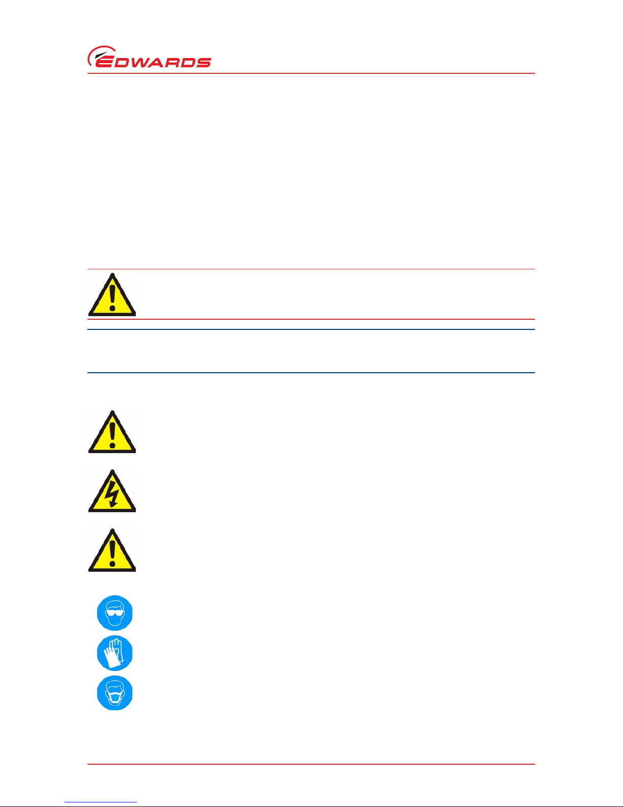
The following IEC warning labels appear on the pump:
WARNING
Warnings are given where failure to observe the instruction could result in injury or death to
people.
Warning - refer to accompanying documentation.
Warning - risk of electric shock.
Warning - trip hazard.
Warning - use protective equipment.
Page 10
S900-01-880 Issue C
Page 2 © Edwards Limited 2 0 08. All rights reserved.
Edwards and the Edwards logo are trademarks of Edwards Limited.
Introduction
The units used throughout this manual conform to the SI international system of units of measurement.
1.2 ATEX directive implications
The booster pump is not designed to meet European ATEX requirements.
1.3 Description
The booster pumps are single stage, positive displacement precision engineered machines. You must use the booster
pump with a suitable backing or roughing pump. The booster pump is not intended for stand-alone operation. The
pump gears provide for quiet operation while maintaining proper impeller timing.
The booster pumps are supplied as standard with keyless timing, drive side roller bearings, mechanical vacuum seal,
and large oil-level sight-glasses. These features provide for ease of maintenance and improve reliability.
The pump identification plate provides specific details ab out the pump, including: pump type; part number and serial
number; and so on. We recommend that you have this information available when you contact Edwards for advice,
parts or service.
Direct drive booster pumps are supplied with hydrocarbon lubricating oil in the oil reservoirs. Standard bareshaft
booster pumps are also supplied with hydrocarbon lubricating oil in the oil reservoirs. Special service (oxyg en service)
bareshaft booster pumps are specially prepared free of hydrocarbons in the factory and are supplied without oil in
the reservoirs. You must use PFPE lubricating oil in special service (oxygen service) pumps.
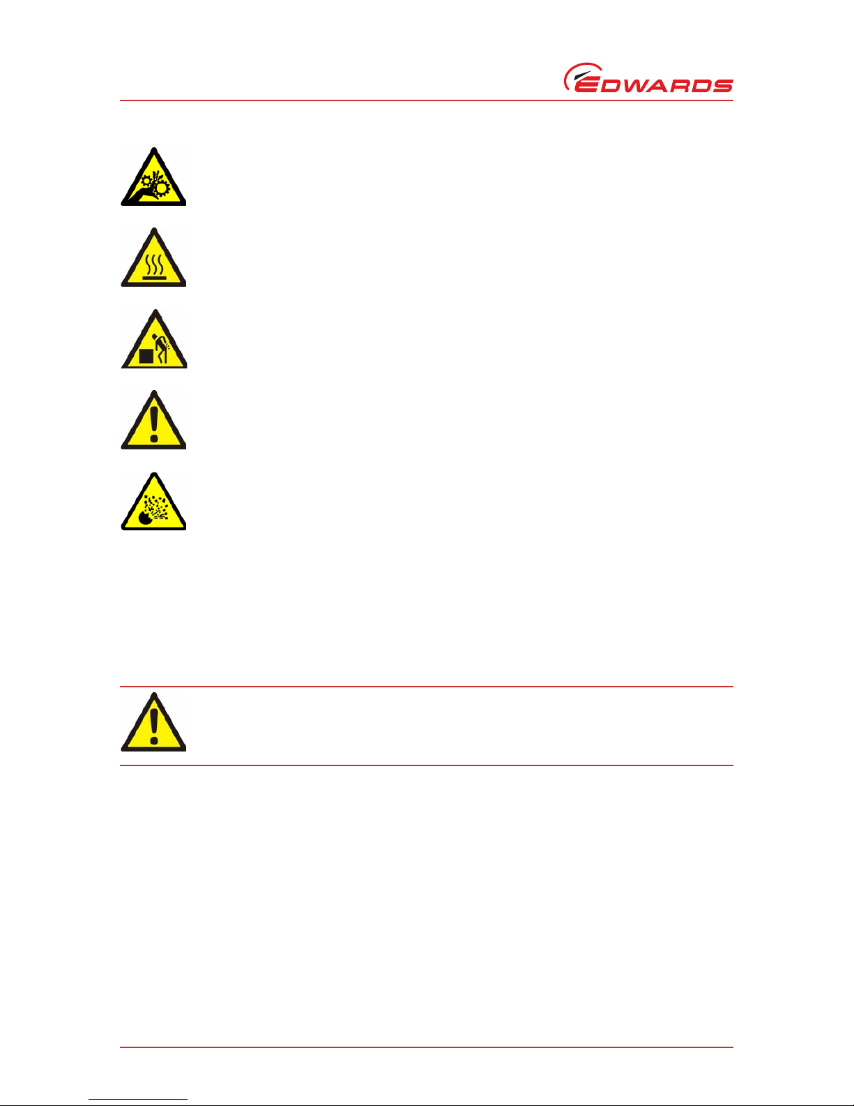
Warning - moving parts present.
Warning - hot surfaces.
Warning - heavy object.
Warning - entanglement.
Warning - possible explosion.
WARNING
Standard booster pumps are not intended for use with hazardous, reactive, flammable and
explosive gases. Consult Edwards for advice before you use a booster pump on one of these
applications.
Page 11

© Edwards Limited 2008. All rights reserved. Page 3
Edwards and the Edwards logo are trademarks of Edwards Limited.
Introduction
S900-01-880 Issue C
MSeal booster pumps have a mechanical shaft seal on the drive shaft, and labyrinth shaft-seals between the gearbox
and the swept volume. Process isolation booster pumps have a mechanical shaft seal on the drive shaft, and
mechanical seals between the gearbox and the swept volume.
The booster pump general arrangements are shown in Figures 1 and 2.
1.4 General information
The booster pumps are available in horizontal (H) and vertical (V) configurations. The models of booster pumps are
the 607, 615 and 622 and these model numbers denote the pump body lengths: 7.0, 15.0 and 2 2.0 inches. The booster
pumps are available as bareshaft (belt driven) pumps, and as direct drive pumps (with shaft-mounted motors).
The booster pump gear centre distance is 6 inches. The bo oster pump have normal operation limits from 800 to 3600
r min-1 (r.p.m.). The volumetric pumping rates increase with body length and rotational speed. Pump components
in contact with the pumped gases are cast iron and carbon steel.
Refer to Table 1 to determine the operational limits for the booster pumps. The limits are based on compression and
pumping speeds for the specific application. Table 1 provides the maximum performance limits of the pumps. The
limits, backing pump speed and gas loads determine the cut-in pressure and continuous operation pressure limits.
Edwards can recommend cut-in and operation limits when supplied with chamber size, backing pump and gas load
information. The first limit reached during operation is the limiting factor. Control devices such as timers and
pressure and temperature switches may be required to properly control the operation of the booster pumps.
1.5 Booster pump models
The booster pumps are available in two versions:
H model booster pumps have vertical connections and are configured for horizontal gas flow through the
pump. (“H” appears in the Item Number of these pumps.)
V model booster pumps have horizontal connections and are configured for vertical gas flow through the
pump. (“V” appears in the Item Number of these pumps.)
The 615 booster pump is available with an optional bypass valve (see Section 1.9) which allow s pump operation from
atmospheric pressure and reduces pump-down time. The booster pumps can be prepared hydrocarbon free for oxygen
service. Variable frequency (speed) drives are available for the pumps.
Table 1 - Application data
Pump model
607 615 615B* 622
Maximum pressure differential 5.06 x 10
4
Pa
506 mbar
380 Torr
5.06 x 10⁴ Pa
506 mbar
380 Torr
Not applicable 3.33 x 10⁴ Pa
333 mbar
250 Torr
Maximum temperature rise 135 ºC
275 ºF
135 ºC
275 ºF
135 ºC
275 ºF
121 ºC
250 ºF
Maximum discharge temperature 191 ºC
375 ºF
191 ºC
375 ºF
191 ºC
375 ºF
177 ºC
350 ºF
Maximum displacement † 2056 m
3h-1
1212 cfm
4412 m3h
-1
2600 cfm
4412 m3h
-1
2600 cfm
6528 m3h
-1
3840 cfm
Inlet and exhaust connection: ASA 6 inches 8 inches 8 inches 8 inches
Noise level average at ultimate vacuum * < 85 dB(A) < 85 dB(A) < 85 dB(A) < 85 dB(A)
* With bypass valve
† At 3600 r min-1 (3600 rpm)
Page 12

S900-01-880 Issue C
Page 4 © Edwards Limited 2 0 08. All rights reserved.
Edwards and the Edwards logo are trademarks of Edwards Limited.
Introduction
You must never operate the booster pump unless it is installed in a proper vacuum system with adequate guarding to
protect people from injury. You must fit safety guards to bareshaft booster pumps before operation.
Note that:
“B” in the pump Item Number specifies that the pump has a bypass valve.
“5H” or “5V” in the pump Item Number specifies that the pump is a process isolation booster pump,
otherwise the pump is an MSeal booster pump.
“HR” or “VR” at the end of the Item Number specifies that the pump is a standard service bareshaft pump
(with hydrocarbon oil), “HR101” or “VR101” at the end of the Item Number specifies that the pump is an
oxygen service (hydrocarbon free) bareshaft pump, otherwise the pump is a standard service pump (with
hydrocarbon oil).
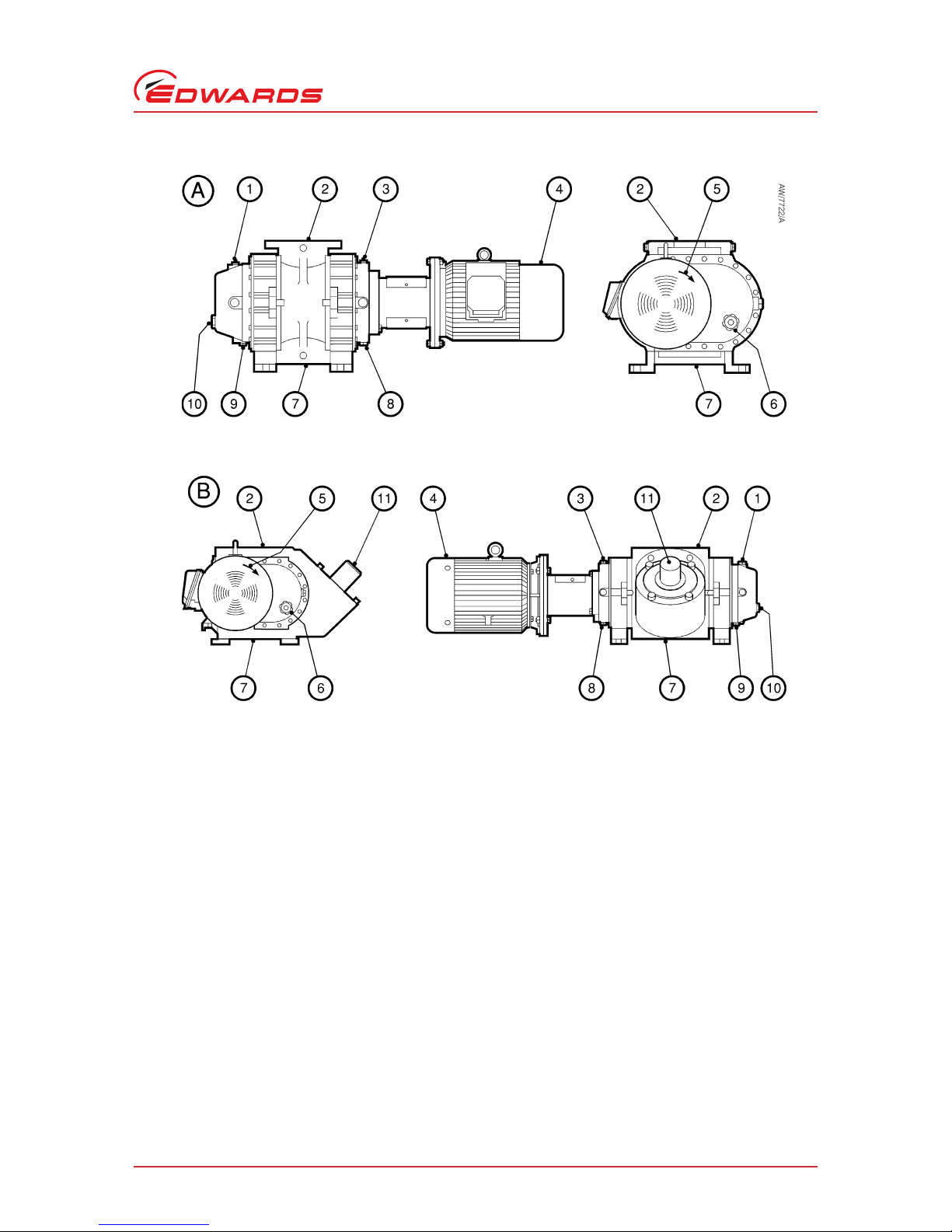
Figure 1 - General arrangement of the H (horizontal) booster
A. Standard direct drive pump
B. Direct drive pump with bypass valve
1. Direction of rotation arrow
2. Motor (IEC frame shown)
3. Oil filler plug (drive end)
4. Inlet
5. Oil filler plug (gear end)
6. Oil-level sight-glass (gear end)
7. Oil drain plug (gear end)
8. Oil drain plug (drive end)
9. Oil-level sight-glass (drive end)
10.Outlet
11.Bypass valve
Page 13
© Edwards Limited 2008. All rights reserved. Page 5
Edwards and the Edwards logo are trademarks of Edwards Limited.
Introduction
S900-01-880 Issue C
Figure 2 - General arrangement of the V (vertical) booster
A. Standard direct drive pump
B. Direct drive pump with bypass valve
1. Oil filler plug (gear end)
2. Inlet
3. Oil filler plug (drive end)
4. Motor (IEC frame shown)
5. Direction of rotation arrow
6. Oil-level sight-glass (drive end)
7. Outlet
8. Oil drain plug (drive end)
9. Oil drain plug (gear end)
10.Oil-level sight-glass (gear end)
11.Bypass valve
Page 14
S900-01-880 Issue C
Page 6 © Edwards Limited 2 0 08. All rights reserved.
Edwards and the Edwards logo are trademarks of Edwards Limited.
Introduction
1.6 Principle of operation
The basic operation of an H (horizontal) booster is shown in Figure 3.
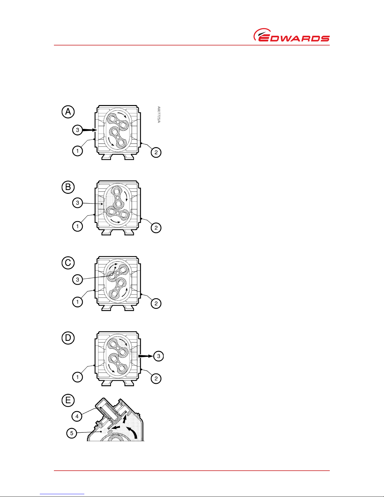
Figure 3 - Principle of operation
Detail A - Gas (3) enters the pump body through the inlet (1).
In the pump body, the upper impeller rotor rotates clo ckwise,
and the lower impeller rotor rotates anticlockwise
(counterclockwise).
Detail B - As the impeller rotors rotate, gas (3) is drawn into
the volume between the pump body wall and the rotors.
Detail C - As the rotors rotate further, gas (3) is trapped
between the pump body wall and the rotors, and is transferred
towards the outlet (2). The rotors rotate with precise timing to
maintain the proper clearances, limiting gas back flow.
Detail D - As the rotors rotate further, the gas (3) is discharged
through the pump outlet (2). The pump discharges four
volumes for every full rotation of the drive shaft.
Detail E: bypass valve operation (only applicable to pumps
with a bypass valve) - The optional integral bypass valve limits
the pressure differential across the pump. During pump
operation, if the compression creates an excessive pressure
differential across the pump, the bypass valve (4) opens, to
allow a portion of the compressed gases (5) to flow back
towards the inlet side of the pump.
Page 15

© Edwards Limited 2008. All rights reserved. Page 7
Edwards and the Edwards logo are trademarks of Edwards Limited.
Introduction
S900-01-880 Issue C
1.7 Bareshaft (belt drive) booster pumps
The booster pumps have been designed to withstand loading from standard V-belts, for standard operation from 800
to 3600 r min-1 (r.p.m.). The loads induced into the drive shaft depend on the power applied to the shaft. Edwards
specifies a minimum pulley diameter for the drive shaft based on motor power. You must never use a pulley with a
smaller diameter than those specified in this manual. Refer to Table 12 for specific details on pulley diame ters.
Edwards can provide booster pumps and motors sized for most applications.
1.8 Direct drive booster pumps (with shaft-mounted motors)
Direct drive eliminates the tension loads associated with belt drives. The direct drive booster pump consists of a
standard booster pump, coupling, motor support, and C-face (NEMA) or D-flange (IEC) motor. Optional variable
frequency drives are available from Edwards to improve performance on booster pumps without bypass valves.
Consult Edwards for application information. Various voltage, frequency, speed and power motors are available.
Large power motors (> 22.37 kW, 30 h.p.) cannot be supported by a motor support alone.
1.9 Integral bypass valve (model 615 pumps only)
Model 615 booster pumps can be supplied with an integral bypass valve for operation from a tmospheric pressure. The
bypass regulates the amount of compression across the booster pump body. The limiting speed for the bypass booster
pump is 3600 r min-1 (r.p.m.). The bypass valve regulates the pressure differential across the booster pump to 7.9 x
103 Pa (79 mbar, 60 Torr). Maximum discharge temperature and maximum temperature rise are the same as for the
standard 615 booster pumps. Under so me operating conditions, it is not possible to o perate the bypass booster pumps
continuously because of the heat generated from gas compression. These conditions depend on chamber size and
backing pump speeds. Consult Edwards if pump-down exceeds 45 minutes. Refer to Figure 3 detail E for a crosssection view of a bypass booster pump.
1.10 Oxygen and reactive gas service
Edwards can prepare bareshaft booster pumps for hazardous gas duties (where pumped gases could react with the
hydrocarbon lubricants in standard pumps). When prepared for hazardous gas du ties, the booster pumps will be free
of hydrocarbons and must be used with inert lubricating oil which will not react with the hazardous gases pumped.
You must take special care when operating booster pumps on oxygen pumping duties: refer to the “Vacuum pump
and vacuum system safety - chemical & industrial systems“ publication (Edwards Publication Number P400-40-100).
Page 16

S900-01-880 Issue C
Page 8 © Edwards Limited 2 0 08. All rights reserved.
Edwards and the Edwards logo are trademarks of Edwards Limited.
Introduction
Page 17

© Edwards Limited 2008. All rights reserved. Page 9
Edwards and the Edwards logo are trademarks of Edwards Limited.
Technical Data
S900-01-880 Issue C
2Technical Data
2.1 Operating and storage conditions
2.2 Pump technical data
Performance data, electrical data and mechanical data for the booster pumps are provided in Tables 3 to 8.
Table 2 - Operating and storage conditions
Ambient operating temperature range 12 to 40 ºC (54 to104 ºF)
Ambient storage temperature range -30 to 70 ºC (-22 to 158 ºF)
Normal surface temperature of the pump body at ultimate
vacuum (operation), ambient temperature of 20 ºC (68 ºF)
50 to 70 ºC (122 to 158 ºF)
Maximum ambient operating humidity 90% RH
Table 3 - Technical data: 607-MH/MV05, 607-MH/MV20, 615-MH/MV10 and 615-MH/MV15 direct drive MSeal
booster pumps (with NEMA motors)
900-607-MH05
900-607-MV05
900-607-MH20
900-607-MV20
900-615-MH10
900-615-MV10
900-615-MH15
900-615-MV15
Pumping speed 1040 m
3h-1
612 cfm
1040 m3h
-1
612 cfm
2210 m3h
-1
1300 cfm
4420 m3h
-1
2600 cfm
Nominal power 3.75 kW
5 hp
15 kW
20 hp
7.5 kW
10 hp
11 kW
15 hp
Voltage 230/460 V ac 208-230/460 V ac 208-230/460 V ac 208-230/460 V ac
Frequency 60 Hz 60 Hz 60 Hz 60 Hz
Phases 3333
Enclosure TEFC IP55 TEFC IP55 TEFC IP55 TEFC IP55
Full load current 13 A/6.6 A 53 A/48 A/24 A 27.2 A/24.6 A/
12.3 A
39.8 A/36 A/18 A
Motor speed 1725 r min
-1
1725 rpm
1760 r min
-1
1760 rpm
1750 r min
-1
1750 rpm
3500 r min
-1
3500 rpm
Recommended fuse/circuit
breaker
20 A/10 A 70 A/35 A 35 A/17.5 A 50 A/25 A
Dimensions Figures 4 and 5 Figures 4 and 5 Figures 4 and 5 Figures 4 and 5
Total mass (pump and
motor)
274 kg
603 lb
406 kg
897 lb
385 kg
847 lb
392 kg
865 lb
Motor mass 34 kg
75 lb
167 kg
367 lb
84 kg
185 lb
91 kg
200 lb
Page 18

S900-01-880 Issue C
Page 10 © Edwards Limited 2008. All rights reserved.
Edwards and the Edwards logo are trademarks of Edwards Limited.
Technical Data
Table 4 - Technical data: 61B-5V10 and 622-5H/5V25 direct drive process isolation booster pump, and 61B-MH/
MV10 61B-MH/MV25 and 622-MH/MV25 direct drive MSeal booster pumps (with NEMA motors)
900-61B-5V10
900-61B-MH10
900-61B-MV10
900-61B-MH25
900-61B-MV25
900-622-MH25
900-622-MV25
900-622-5H25
900-622-5V25
Pumping speed 2210 m
3h-1
1300 cfm
2210 m3h
-1
1300 cfm
4420 m3h
-1
2600 cfm
6528 m3h
-1
3840 cfm
Nominal power 7.5 kW
10 hp
7.5 kW
10 hp
18.6 kW
25 hp
18.6 kW
25 hp
Voltage 208-230/460 V ac 208-230/460 V ac 208-230/460 V ac 208-230/460 V ac
Frequency 60 Hz 60 Hz 60 Hz 60 Hz
Phases 3 3 3 3
Enclosure TEFC IP55 TEFC IP55 TEFC IP55 TEFC IP55
Full load current 27.2 A/24.6 A/
12.3 A
27.2 A/24.6 A/
12.3 A
66.3 A/60 A/30 A 66.3 A/60 A/30 A
Motor speed 1750 r min
-1
1750 rpm
1750 r min
-1
1750 rpm
3500 r min
-1
3500 rpm
3500 r min
-1
3500 rpm
Recommended fuse/circuit
breaker
35 A/17.5 A 35 A/17.5 A 80 A/40 A 80 A/40 A
Dimensions Figure 7 Figures 6 and 7 Figures 6 and 7 Figures 4 and 5
Total mass (pump and motor) 392 kg
865 lb
392 kg
865 lb
533 kg
1175 lb
619 kg
1365 lb
Motor mass 84 kg
185 lb
84 kg
185 lb
167 kg
367 lb
167 kg
367 lb
Page 19

© Edwards Limited 2008. All rights reserved. Page 11
Edwards and the Edwards logo are trademarks of Edwards Limited.
Technical Data
S900-01-880 Issue C
Table 5 - Technical data: 607MHR/M VR601 and 615MHR/MVR601 direct drive MSeal booster pumps (with IEC
motors)
900607MHR601*
900607MVR601*
900615MHR601*
900615MVR601*
50 Hz operation 60 Hz operation 50 Hz operation 60 Hz operation
Pumping speed 1734 m3h
-1
1020 cfm
2080 m3h
-1
1224 cfm
3684 m3h
-1
2167 cfm
4420 m3h
-1
2600 cfm
Nominal power 7.5 kW
10 hp
7.5 kW
10 hp
11 kW
15 hp
11 kW
15 hp
Voltage 200/400 V ac 230/460 V ac 200/400 V ac 230/460 V ac
Frequency 50 Hz 60 Hz 50 Hz 60 Hz
Phases 3 3 3 3
Enclosure IP55 IP55 IP55 IP55
Full load current 27.8 A/13.9 A 24 A/12 A 40 A/20 A 34.4 A/17.2 A
Motor speed 2905 r min
-1
2905 rpm
3510 r min
-1
3510 rpm
2940 r min
-1
2940 rpm
3555 r min
-1
3555 rpm
Recommended fuse/circuit breaker 40 A/20 A 35 A/17.5 A 60 A/30 A 50 A/25 A
Dimensions Figures 4 and 5 Figures 4 and 5 Figures 4 and 5 Figures 4 and 5
Total mass (pump and motor) 330 kg
726 lb
330 kg
726 lb
446 kg
981 lb
446 kg
981 lb
Motor mass 74 kg
163 lb
74 kg
163 lb
118 kg
260 lb
118 kg
260 lb
* These are CE-compliant dual-frequency booster pumps
Page 20

S900-01-880 Issue C
Page 12 © Edwards Limited 2008. All rights reserved.
Edwards and the Edwards logo are trademarks of Edwards Limited.
Technical Data
Table 6 - Technical data: 61BMHR/MVR6 01 and 622MHR/MVR601 direct drive MSeal booster pumps (with IEC
motors)
90061BMHR601 *
90061BMVR601 *
900622MHR601 *
900622MVR601 *
50 Hz operation 60 Hz operation 50 Hz operation 60 Hz operation
Pumping speed 3684 m3h
-1
2167 cfm
4420 m3h
-1
2600 cfm
5440 m3h
-1
3200 cfm
6258 m3h
-1
3840 cfm
Nominal power 18.5 kW
25 hp
18.5 kW
25 hp
18.5 kW
25 hp
18.5 kW
25 hp
Voltage 200/400 V ac 230/460 V ac 200/400 V ac 230/460 V ac
Frequency 50 Hz 60 Hz 50 Hz 60 Hz
Phases 3333
Enclosure IP55 IP55 IP55 IP55
Full load current 57.2 A/28.6 A 67 A/33.5 A 57.2 A/28.6 A 67 A/33.5 A
Motor speed 2950 r min
-1
2950 rpm
3550 r min
-1
3550 rpm
2950 r min
-1
2950 rpm
3555 r min
-1
3555 rpm
Recommended fuse/circuit breaker 70 A/35 A 90 A/50 A 70 A/35 A 90 A/50 A
Dimensions Figures 6 and 7 Figures 6 and 7 Figures 6 and 7 Figures 6 and 7
Total mass (pump and motor) 538 kg
1185 lb
538 kg
1185 lb
624 kg
1375 lb
624 kg
1375 lb
Motor mass 116 kg
260 lb
74 kg
163 lb
145 kg
319 lb
145 kg
319 lb
* These are CE-compliant dual-frequency booster pumps
Page 21

© Edwards Limited 2008. All rights reserved. Page 13
Edwards and the Edwards logo are trademarks of Edwards Limited.
Technical Data
S900-01-880 Issue C
Table 7 - Technical data: bareshaft MSeal booster pumps
900-607-MHR
900607MHR101
900-615-MHR
900615MHR101
900-61B-MHR
90061BMHR101
900-622-MHR
900622MHR101
Dimensions Figure 8 Figure 8 Figure 10 Figure 8
Pump mass 220 kg
483 lb
279 kg
614 lb
342 kg
753 lb
429 kg
945 lb
900-607-MVR
900607MVR101
900-615-MVR
900615MVR101
900-61B-MVR
90061BMVR101
900-622-MVR
900622MVR101
Dimensions Figure 9 Figure 9 Figure 11 Figure 9
Pump mass 218 kg
480 lb
277 kg
610 lb
341 kg
749 lb
428 kg
941 lb
Table 8 - Technical data: bareshaft process isolation booster pumps
900-607-5HR
9006075HR101
900-615-5HR
9006155HR101
900-61B-5HR
90061B5HR101
900-622-5HR
9006225HR101
Dimensions Figure 8 Figure 8 Figure 10 Figure 8
Pump mass 235 kg
516 lb
294 kg
647 lb
357 kg
786 lb
445 kg
978 lb
900-607-5VR
9006075VR101
900-615-5VR
9006155VR101
900-61B-5VR
90061B5VR101
900-622-5VR
9006225VR101
Dimensions Figure 9 Figure 9 Figure 11 Figure 9
Pump mass 224 kg
492 lb
283 kg
623 lb
346 kg
762 lb
433 kg
954 lb
Page 22

S900-01-880 Issue C
Page 14 © Edwards Limited 2008. All rights reserved.
Edwards and the Edwards logo are trademarks of Edwards Limited.
Technical Data
Figure 4 - Direct drive H (horizontal) booster pump dimensions
Pump
Dimensions: mm (inch)
ABCDEFG
900-607-MH05 228 (8.5) 543 (21.4) 406 (16.0) 1087 (42.8) 309 (12.1) 292 (11.5) 270 (10.7)
900-607-MH20 228 (8.5) 543 (21.4) 406 (16.0) 1225 (48.2) 309 (12.1) 292 (11.5) 270 (10.7)
900-615-MH10 228 (8.5) 543 (21.4) 406 (16.0) 1367 (53.8) 409 (16.1) 292 (11.5) 470 (18.5)
900-615-MH15 228 (8.5) 543 (21.4) 406 (16.0) 1367 (53.8) 409 (16.1) 292 (11.5) 470 (18.5)
900-622-MH25 228 (8.5) 543 (21.4) 438 (17.3) 1657 (65.2) 498 (19.6) 292 (11.5) 648 (25.5)
900-622-5H25 228 (8.5) 543 (21.4) 438 (17.3) 1657 (65.2) 498 (19.6) 292 (11.5) 648 (25.5)
900607MHR601 228 (8.5) 543 (21.4) 406 (16.0) 1164 (46.6) 309 (12.1) 292 (11.5) 270 (10.7)
900615MHR601 228 (8.5) 543 (21.4) 406 (16.0) 1515 (59.6) 409 (16.1) 292 (11.5) 470 (18.5)
900622MHR601 228 (8.5) 543 (21.4) 438 (17.3) 1694 (66.9) 490 (19.3) 292 (11.5) 648 (25.5)
Page 23

© Edwards Limited 2008. All rights reserved. Page 15
Edwards and the Edwards logo are trademarks of Edwards Limited.
Technical Data
S900-01-880 Issue C
Figure 5 - Direct drive V (vertical) booster pump dimensions
Pump
Dimensions: mm (inch)
ABCDEF
900-607-MV05 254 (10.0) 308 (12.1) 1087 (42.8) 502 (19.6) 406 (16.0) 350 (13.8)
900-607-MV20 254 (10.0) 308 (12.1) 1224 (48.2) 502 (19.6) 406 (16.0) 350 (13.8)
900-615-MV10 454 (17.9) 409 (16.1) 1367 (53.8) 502 (19.6) 406 (16.0) 350 (13.8)
900-615-MV15 454 (17.9) 409 (16.1) 1367 (53.8) 502 (19.6) 406 (16.0) 350 (13.8)
900-622-MV25 648 (25.5) 496 (19.6) 1657 (55.2) 502 (19.6) 473 (18.6) 350 (13.8)
900-622-5V25 648 (25.5) 496 (19.6) 1657 (55.2) 502 (19.6) 473 (18.6) 350 (13.8)
900607MVR601 254 (10.0) 308 (12.1) 1184 (46.6) 537 (21.1) 406 (16.0) 350 (13.8)
900615MVR601 454 (17.9) 409 (16.1) 1526 (60.2) 581 (22.9) 432 (17.0) 350 (13.8)
900622MVR601 648 (25.5) 409 (16.1) 1696 (66.8) 579 (22.8) 473 (18.6) 350 (13.8)
Page 24

S900-01-880 Issue C
Page 16 © Edwards Limited 2008. All rights reserved.
Edwards and the Edwards logo are trademarks of Edwards Limited.
Technical Data
Figure 6 - Direct drive H (horizontal) booster pump with bypass valve dimensions
Figure 7 - Direct drive V (vertical) booster pump with bypass valve dimensions
Pump
Dimensions: mm (inch)
ABCDEFG
900-61B-MH10 229 (9.0) 763 (30.0) 406 (16.0) 1367 (53.8) 409 (16.1) 292 (11.5) 471 (18.5)
900-61B-MH25 229 (9.0) 763 (30.0) 406 (16.0) 1479 (58.2) 409 (16.1) 292 (11.5) 471 (18.5)
90061BMHR601 229 (9.0) 763 (30.0) 406 (16.0) 1515 (59.6) 409 (16.1) 292 (11.5) 471 (18.5)
Pump
Dimensions: mm (inch)
ABCDEF
900-61B-5V10 349 (13.8) 406 (16.0) 722 (28.4) 1367 (53.8) 409 (16.1) 454 (17.9)
900-61B-MV10 349 (13.8) 406 (16.0) 722 (28.4) 1367 (53.8) 409 (16.1) 454 (17.9)
900-61B-MV25 349 (13.8) 406 (16.0) 722 (28.4) 1479 (58.2) 409 (16.1) 454 (17.9)
90061BMVR601 349 (13.8) 406 (16.0) 791 (31.1) 1520 (59.9) 413 (16.3) 454 (17.9)
Page 25

© Edwards Limited 2008. All rights reserved. Page 17
Edwards and the Edwards logo are trademarks of Edwards Limited.
Technical Data
S900-01-880 Issue C
Figure 8 - Bareshaft H (horizontal) booster pump dimensions
* 9 mm (3/8 inch) square key
Pump
Dimensions: mm (inch)
ABCDEFGHJK
900-607-MHR 228
(8.5)
543
(21.4)
406
(16.0)
641
(25.2)
309
(12.1)
292
(11.5)
270
(10.7)76(3.0)43(1.7)
*
900-615-MHR 228
(8.5)
543
(21.4)
406
(16.0)
843
(33.2)
409
(16.1)
292
(11.5)
470
(18.5)76(3.0)43(1.7)
*
900-622-MHR 228
(8.5)
543
(21.4)
438
(17.3)
1018
(40.1)
498
(19.6)
292
(11.5)
648
(25.5)76(3.0)43(1.7)
*
Page 26

S900-01-880 Issue C
Page 18 © Edwards Limited 2008. All rights reserved.
Edwards and the Edwards logo are trademarks of Edwards Limited.
Technical Data
Figure 9 - Bareshaft V (vertical) booster pump dimensions
* 9 mm(3/8 inch) square key
Pump
Dimensions: mm (inch)
ABCDEFGHJ
900-607-MVR 254
(10.0)
308
(12.1)
641
(25.2)
502
(19.8)
406
(16.0)
350
(13.8)76(3.0)
43
(1.7)
*
900-615-MVR 454
(17.9)
409
(16.1)
843
(33.2)
502
(19.8)
406
(16.0)
350
(13.8)76(3.0)
43
(1.7)
*
900-622-MVR 636
(25.0)
497
(19.6)
1018
(40.1)
502
(19.8)
438
(17.2)
350
(13.8)76(3.0)
43
(1.7)
*
Page 27

© Edwards Limited 2008. All rights reserved. Page 19
Edwards and the Edwards logo are trademarks of Edwards Limited.
Technical Data
S900-01-880 Issue C
Figure 10 - Bareshaft H (horizontal) booster pump with bypass valve dimensions
* 9 mm (3/8 inch) square key
Pump
Dimensions: mm (inch)
ABCDEFGHJ
900-61B-MVR 350
(13.8)
431
(17.0)
718
(28.3)
843
(33.2)
411
(16.2)
454
(17.9)76(3.0)
43
(1.7)
*
Page 28

S900-01-880 Issue C
Page 20 © Edwards Limited 2008. All rights reserved.
Edwards and the Edwards logo are trademarks of Edwards Limited.
Technical Data
Figure 11 - Bareshaft V (vertical) booster pump with bypass valve dimensions
Pump
Dimensions: mm (inch)
ABCDEFGHJ
900-61B-MVR 350
(13.8)
431
(17.0)
718
(28.3)
843
(33.2)
411
(16.2)
454
(17.9)76(3.0)
43
(1.7)
*
Page 29

© Edwards Limited 2008. All rights reserved. Page 21
Edwards and the Edwards logo are trademarks of Edwards Limited.
Technical Data
S900-01-880 Issue C
2.3 Item numbers
Table 9 - Item numbers: direct drive MSeal booster pumps and process isolation booster pumps
Nominal supply voltage and
frequency
Nominal
power
Item Number
MSeal booster
pumps
Process isolation
booster pumps
230 V, 60 Hz, 3-phase
460 V, 60 Hz, 3-phase
3.75 kW, 5 h.p.
3.75 kW, 5 h.p.
900-607-MH05
900-607-MV05
230 V, 60 Hz, 3-phase
460 V, 60 Hz, 3-phase
15 kW, 20 h.p.
15 kW, 20 h.p.
900-607-MH20
900-607-MV20
230 V, 60 Hz, 3-phase
460 V, 60 Hz, 3-phase
7.5 kW, 10 h.p.
7.5 kW, 10 h.p.
900-615-MH10
900-615-MV10
230 V, 60 Hz, 3-phase
460 V, 60 Hz, 3-phase
11 kW, 15 h.p.
11 kW, 15 h.p.
900-615-MH15
900-615-MV15
230 V, 60 Hz, 3-phase
460 V, 60 Hz, 3-phase
7.5 kW, 10 h.p.
7.5 kW, 10 h.p.
900-61B-MH10
900-61B-MV10
900-61B-5V10
230 V, 60 Hz, 3-phase
460 V, 60 Hz, 3-phase
18.5 kW, 25 h.p.
18.5 kW, 25 h.p.
900-61B-MH25
900-61B-MV25
230 V, 60 Hz, 3-phase
460 V, 60 Hz, 3-phase
18.5 kW, 25 h.p.
18.5 kW, 25 h.p.
900-622-MH25
900-622-MV25
200 V, 50 Hz, 3-phase
400 V, 50 Hz, 3-phase
7.5 kW, 10 h.p.
7.5 kW, 10 h.p.
900607MHR601
900607MVR601
230 V, 60 Hz, 3-phase
460 V, 60 Hz, 3-phase
7.5 kW, 10 h.p.
7.5 kW, 10 h.p.
900607MHR601
900607MVR601
200 V, 50 Hz, 3-phase
400 V, 50 Hz, 3-phase
11 kW, 15 h.p.
11 kW, 15 h.p.
900615MHR601
900615MVR601
230 V, 60 Hz, 3-phase
460 V, 60 Hz, 3-phase
11 kW, 15 h.p.
11 kW, 15 h.p.
900615MHR601
900615MVR601
200 V, 50 Hz, 3-phase
400 V, 50 Hz, 3-phase
18.5 kW, 25 h.p.
18.5 kW, 25 h.p.
90061BMHR601
90061BMVR601
230 V, 60 Hz, 3-phase
460 V, 60 Hz, 3-phase
18.5 kW, 25 h.p.
18.5 kW, 25 h.p.
90061BMHR601
90061BMVR601
200 V, 50 Hz, 3-phase
400 V, 50 Hz, 3-phase
18.5 kW, 25 h.p.
18.5 kW, 25 h.p.
900622MHR601
900622MVR601
900-622-5H25
900-622-5V25
230 V, 60 Hz, 3-phase
460 V, 60 Hz, 3-phase
18.5 kW, 25 h.p.
18.5 kW, 25 h.p.
900622MHR601
900622MVR601
Page 30

S900-01-880 Issue C
Page 22 © Edwards Limited 2008. All rights reserved.
Edwards and the Edwards logo are trademarks of Edwards Limited.
Technical Data
Table 10 - Item numbers: bareshaft MSeal booster pumps and process isolation booster pumps
Pump type
Item Number
Standard (hydrocarbon) pumps
Oxygen service
(hydrocarbon free) pumps
Bareshaft Mseal
booster pumps
900-607-MHR 900607MHR101
900-607-MVR 900607MVR101
900-615-MHR 900615MHR101
900-615-MVR 900615MVR101
900-61B-MHR 90061BMHR101
900-61B-MVR 90061BMVR101
900-622-MHR 900622MHR101
900-622-MVR 900622MVR101
Bareshaft process isolation
booster pumps
900-607-5HR 9006075HR101
900-607-5VR 9006075VR101
900-615-5HR 9006155HR101
900-615-5VR 9006155VR101
900-61B-5HR 90061B5HR101
900-61B-5VR 90061B5VR101
900-622-5HR 9006225HR101
900-622-5VR 9006225VR101
Page 31

© Edwards Limited 2008. All rights reserved. Page 23
Edwards and the Edwards logo are trademarks of Edwards Limited.
Installation
S900-01-880 Issue C
3 Installation
3.1 Safety
A suitably trained and supervised technician must install the booster pump. The installation technician must
obey all local and national safety requirements.
Ensure that the installation technician is familiar with the safety procedures which relate to the pump oil
and the products processed by the pumping system.
Consult Edwards publication P400-40-100 (Vacuum pump and va cuum system safety - chemical and industrial
systems) before you install and use the booster pump to process hazardous or flammable materials.
Vent and purge the pumping system b efore you start inst allation work.
Check that all the required components are available and of the correct type before you start work.
Ensure that debris does not get into the booster pump when you install it.
Disconnect the other components in the pumping system from the electrical supply so that they cannot be
operated accidentally.
Do not reuse 'O' rings and co-seals.
Ensure that all electrical cables and purge gas pipelines are safely positioned, secured and routed, so that
they do not present a trip hazard.
Provide adequate access to all pump servicing points and oil-level sight-glasses.
Leak test the system after installation work is complete and seal any leaks found, to prevent leakage of
hazardous substances out of the system and leakage of air into the system.
3.2 System design considerations
Consider the following points when you design the pumping system:
You must mount the booster pump on a firm, level surface.
Adequately support vacuum pipelines to prevent the transmission of stress to pipeline joints.
If necessary, incorporate flexible pipelines in your system pipelines to reduce the transmission of vibration
and to prevent loading of the coupling joints. If you use flexible pipelines, you must ensure that you use
flexible pipelines which have a maximum pressure rating which is greater than the highest pressure that can
be generated in the system.
Ensure that the design incorporates all appropriate safety precautions if toxic, inflammable or explosive
gases or particulates will be pumped. Your design must ensure that:
Where a flammable gas is pumped, the concentrations of the gas in air must be less than 25% of its LEL
(Lower Explosive Limit) concentrations.
Where a toxic gas is pumped, the concentration of the gas must be less than 25% of the occupational
exposure limit for the gas.
Where a toxic or asphyxiant gas is pumped, the booster pump must be located in a well-ventilated area.
WARNING
Obey the safety instructions listed below and take note of appropriate precautions. If you do not,
you can cause injury to people and damage to equipment.
Page 32

S900-01-880 Issue C
Page 24 © Edwards Limited 2008. All rights reserved.
Edwards and the Edwards logo are trademarks of Edwards Limited.
Installation
You must be able to purge the pu mping sy stem with an inert ga s when you shut down the p umping system, to
dilute dangerous gases to safe concentrations. Contact Edwards or your supplier if you are in doubt.
If the booster pump is to be fitted in a new system, ensure that all preliminary pipelines have been installed and that
a suitable base for the booster pump has been prepared before you sta rt installation.
Ensure that the following services and facilities are available for connection to the booster pump:
Electrical Supply.
Backing pump.
Inlet screen (if required, to prevent debris from entering the pump during commissioning).
3.3 Unpack and inspect
Remove all packing materials, remove the booster pump from its packing box, remove the protective covers from
the inlet and exhaust ports, and inspect the pump.
If the booster pump is damaged, notify the supplier and your carrier in writing within three days; state the Item
Number of the pump together with the order number and supplier's invoice n umber. Retain all packing materia ls for
inspection. Do not use the pump if it is damaged.
If the booster pump is not to be used immediately, refit the protective covers. Store the pump in suitable conditions
as described in Section 6 of this manual.
3.4 Move the booster pump to its operating location
Use a fork-lift truck to move the booster pump (attached to the shipping crate) to the installation location. Lift the
booster pump with the forks well outward of the centre of mass, to prevent the booster pump tipping over when you
move it.
When the booster pump has been unpacked and disconnected from its shipping crate, lift the pump; refer to Figure
12 and use one of the following two methods:
1. To use lifting-bolts and chains (see details A and B):
Fit two 3/4-10 lifting bolts (1, not supplied) to the pump.
On a booster pump with a motor: fit a suitable size lifting bolt to the motor (if necessary).
Attach lifting chains to the lifting bolts (1, 2) and connect the chains to your lifting equipment.
2. To use slings (see detail C):
Attach slings (4) around the pump body.
Connect the slings to your lifting equipment.
You must use lifting equipment and chains/slings which are suitably rated for the mass of the pump.
Use caution when you move a booster pump with a direct drive motor attached; fix the pump in position immediately
after it has been located.
Refer to Tables 4 to 8 for the mass of the pump, and to Table 11 and Figure 12 for the centre of mass location.
WARNING
Use suitable lifting equipment to remove the booster pump from its packaging. If you do not, you
can cause injury to people, or you can damage equipment. Refer to Section 2.2 for pump mass.
Page 33

© Edwards Limited 2008. All rights reserved. Page 25
Edwards and the Edwards logo are trademarks of Edwards Limited.
Installation
S900-01-880 Issue C
Figure 12 - Lifting the booster pump
A. Lifitng H (horizontal) pumps with
chains and lifting bolts
B. Lifting V (vertical) pumps with
chains and lifting bolts
C. Lifting pumps with slings
D. Centre of mass distance: see
Table 11
1. Lifting bolt (on booster pump)
2. Lifting-bolt (on motor)
3. Centre of mass
4. Slings
Page 34

S900-01-880 Issue C
Page 26 © Edwards Limited 2008. All rights reserved.
Edwards and the Edwards logo are trademarks of Edwards Limited.
Installation
Table 11 - Centre of mass dimensions
North American direct drive
booster pumps
UK/Europe/Rest of the world direct drive
booster pumps
Item Number
Centre of mass (Figure 12
dimension 'D'):
mm (inches)
Item Number
Centre of mass
(Figure 12
dimension 'D'):
mm (inches)
900-607-MH05 68 (2.75) 900607MHR601 193 (7.6)
900-607-MH20 380 (15) 900607MVR601 193 (7.6)
900-607-MV05 68 (2.75) 900615MHR601 172 (6.8)
900-607-MV20 380 (15) 900615MVR601 172 (6.8)
900-615-MH10 156 (6.1) 90061BMHR601 275 (10.8)
900-615-MV10 156 (6.1) 90061BMVR601 275 (10.8)
900-615-MH15 172 (6.8) 900622MHR601 265 (10.4)
900-615-MV15 172 (6.8) 900622MVR601 265 (10.4)
900-61B-MH10 115 (4.5)
900-61B-MV10
900-61B-5V10
115 (4.5)
900-61B-MH25 275 (10.8)
900-61B-MV25 275 (10.8)
900-622-MH25
900-622-5H25
265 (10.4)
900-622-MV25
900-622-5V25
265 (10.4)
Bareshaft MSeal booster pumps Bareshaft process isolation booster pumps
Item Number Centre of mass (Figure 12
dimension 'D'):
mm (inches)
Item Number Centre of mass (Figure 12
dimension 'D'):
mm (inches)
900-607-MHR
900607MHR101
16 (0.6) 900-607-5HR
9006075HR101
16 (0.6)
900-607-MVR
900607MVR101
16 (0.6) 900-607-5VR
9006075VR101
16 (0.6)
900-615-MHR
900615MHR101
16 (0.6) 900-615-5HR
9006155HR101
16 (0.6)
900-615-MVR
900615MVR101
16 (0.6) 900-615-5VR
9006155VR101
16 (0.6)
900-61B-MHR
90061BMHR101
16 (0.6) 900-61B-5HR
90061B5HR101
16 (0.6)
900-61B-MVR
90061BMVR101
16 (0.6) 900-61B-5VR
90061B5VR101
16 (0.6)
900-622-MHR
900622MHR101
16 (0.6) 900-622-5HR
9006225HR101
16 (0.6)
900-622-MVR
900622MVR101
16 (0.6) 900-622-5VR
9006225VR101
16 (0.6)
Page 35

© Edwards Limited 2008. All rights reserved. Page 27
Edwards and the Edwards logo are trademarks of Edwards Limited.
Installation
S900-01-880 Issue C
3.5 Locate the booster pump
You must mount the booster pump on a smooth, flat, level surface. The degree of variation in level should not exceed
5.2 mm m-1 (0.063 inch ft-1) in any direction. Check that all four pump feet contact the mounting base. Do not distor t
the booster pump body. You must securely fix the booster pump in position before you operate it.
Before you install the pump, check that there are no foreign materials or debris in the vacuum pipelines or in the
impeller cavities in the body of the pump. Check that the impellers rotate freely.
The booster pumps are designed for optimal performance in clean environments with ambient temperatures as
specified in Section 2.1. If you use the booster pumps in areas of higher temperatures, this will result in higher
discharge temperatures, and possible over-temperature cut-outs. If you use the booster pumps in dirty locations or
where oil vapour is present, this can result in overheating of the motor, belt slippage, or premature wear. When the
pump is used in a dirty environment, ensure that you inspect and clean the equipment as necessary.
Locate the pump as close as possible to the equipment/chamber which will be evacuated. Position the pump so that
electrical and vacuum pipeline connections can be easily made. Provide adequate access space around and above
the pump, so that the pump can be easily serviced. Avoid long lengths of vacuum pipeline from the equipment/
chamber being evacuated to the booster pu mp.
The booster pumps are precision balanced devices. You must mount the booster pump on a sufficiently rigid base,
and secure it to the floor to reduce potential system vibration. Vacuum pipelines attached to the booster pump can
vibrate excessively if they are not properly supported or secured. Booster pump vibration is usually the results of
insufficient support.
3.6 Connect the vacuum and exhaust pipelines
CAUTION
Install a removable inlet filter so that particles, debris or loose components cannot enter the pump during
commissioning.
All vacuum pipelines should be as short as possible and should be no smaller than the diameter of the booster pump
inlet. When you need to install a long length of pipeline, use pipe which has a diameter larger than the diameter of
the pump inlet. Conductance-check the pipelines to ensure that the pumping speed of the system will not be
decreased. Do not install restrictive pipelines or valves in the exhaust pipeline; these may cause the exhaust pressure
to exceed atmospheric pressure. If necessary, consult Edwards for advice and assistance when you need to size long
lengths of pipelines.
Use a clean rag dampened with Loctite Safety Solvent (or another cleaning solution compatible with the gases to be
pumped) to clean the booster pump impellers and flanges if they have accumulated dirt during installation or storage.
It is important that the flanges are clean; if they are not, you will not be able to obtain a good vacuum seal.
Install an isolation valve in the foreline to the booster pump, so that the pump can be isolated from the chamber/
vacuum system.
WARNING
Use suitable lifting equipment to move the booster pump. If you do not, you can injure yourself or
damage the pump. Refer to Section 2 and Table 11 for pump mass information.
WARNING
Install all pipelines so that they do not present a trip hazard. If you do not, you can cause injury
to people.
Page 36

S900-01-880 Issue C
Page 28 © Edwards Limited 2008. All rights reserved.
Edwards and the Edwards logo are trademarks of Edwards Limited.
Installation
3.6.1 Vacuum inlet pipeline
CAUTION
Ensure that foreign matter (particulate) cannot get into the pump. If it does, it can cause serious damage and
premature failure of internal pump part.
Ensure that the vacuum pipeline is leak-tight. Install a flexible connection betw een the b ooster pump i nlet and the
vacuum pipeline, to reduce vibration and prevent booster pump body distortions. Properly support the pipeli nes, to
minimise vibration. You must not use the body of the booster pump to suppo rt long lengths of pipelines.
We recommend that you install a high-vacuum, fully-opening valve, for ease of start-up and so that you can check
the pump ultimate pressure with no gas throughput. This valve will allow you to isolate the vacuum pumps from the
vacuum system. We recommend that you install a vacuum pressure gauge, so that you can monitor pump
performance. Install a vent valve in the booster pump inlet or foreline. Install a filte r-silencer, to prevent the entry
of foreign materials into the system.
Ensure that the vacuum system and connecting pipelines are clean and free of weld splatter, dirt or grit.
Edwards recommends that you install inlet filters and traps, to prevent entry of foreign matter. If you use inlet filters
and traps, we recommend that you change the pump oil more frequently.
You may need to install other devices such as interstage temperature switch es, timers, vacuum pressure switches
and so on, to protect the booster pump from thermal and mechanical overload. This will depend on the size of the
booster pump, the backing pump capacity and vacuum chamber size.
3.6.2 Accessory port pipelines
Accessory connection ports are provided in the body of the booster pump. You may use these ports to connect vent
valves and vacuum pressure gauges. Vacuum pressure gauges should be connected as follows: remove the 0.5 inch 'O'
ring plug (0.75-16 straight thread) and fit a vacuum ball valve, connected to an elevated vacuum pressure gauge. Use
a short run of vacuum pipe so that the valve is not too close to the hot body of the booster pump.
Coat all threaded vacuum joints with a liquid thread sealant (such as Loctite 714 or equivalent). Do not use tape
thread sealant, which will create small vacuum leaks.
3.6.3 Exhaust pipeline
The diameter of the exhaust pipeline must be no smaller th an the diameter of the booster pump outlet. Ensure that
the exhaust gases (which may include pump oil and process gases) are safely handled and trea ted, in accordance with
local, State and National regulations.
When you install a horizontal booster pump on an oil-sealed backing pump, mount the booster pump above the
backing pump inlet, so that oil does not collect in the booster pump. Install sample ports in the exhaust pipeline, so
that you can check system temperatures and pressures. Do not install restrictive piping or valves in the exhaust
pipeline, as these may cause the exhaust pressure to exceed atmospheric pressure.
WARNING
The temperature of parts of the exhaust pipeline may exceed 70 °C (160 °F). Under extreme
conditions, surfaces of the booster pump may reach 190 °C (375 °F). Provide adequate guarding
and warnings, to protect people from the hot surfaces.
Page 37

© Edwards Limited 2008. All rights reserved. Page 29
Edwards and the Edwards logo are trademarks of Edwards Limited.
Installation
S900-01-880 Issue C
3.7 Belt drive booster pump installation
Ensure that the alignment of the pulleys and the tension of the booster pump drive belt are correct. Comply with the
installation requirements specified in this manual and inspect the drive system regularly, to avoid mechanical
problems and unnecessary repairs. Belt axial load should be less than 890 N (200 lb). Table 12 shows the minimum
permissible pulley diameters. Contact Edwards for advice if you want to use a motor with a power rating which
exceeds 30 kW (40 h.p.). Obey all of the safety precautions outlined in Section 3.1
Pulley misalignment can damage the bearing, belts and seal(s). Pulley alignment does n ot change d uring operation.
The motor and booster pump drive shafts must be parallel to avoid uneven loading of belts. Your motor and drive
components must comply with local and national safety regulations. Check for free rotation of the booster pump
before you start the booster pump.
New belts usually lose some tension during initial operation, and you should re-check the belts during the first few
days of operation. Tension all belts in accordance with the belt manufacturer's instructions. Excessive tension can
induce unnecessary loading on the booster pump bearings and bending moments on the booster pump drive shaft.
Extreme over-tensioning may cause the pump drive shaft to fail, due to fatigue damage.
Booster pumps with belt drive systems supplied by Edwards have the pulley and belt tension already preset. Recheck
the alignment and tension (See Tables 13 and 14) before initial operation; use the following procedure:
1. Ensure that the shaft, hub and pulley components are free of lubricants, corrosion and protective coatings.
2. Check the pulley alignment with a straight edge or tight cord. The pulley faces must contact the straight edge a t
all four points. Misalignment will significantly increase belt wear.
3. If pulley alignment or removal is required: loosen the motor hub set screws several turns; remove one set screw
completely; install the set screw in the centre position and then tighten the screw to free the locking bush.
Reposition the pulley and then reinstall the set screws in the original position in the locking bush. Tighten the
set screws evenly to the specified torque. Note that the locking bush number is stamped on the inner hub face.
4. Belt span distance, belt deflection and deflection force determine the correct belt tension. Determine the span
distance between contact points on the pulleys. The deflection must be 0.397 mm per 25.4 mm of span (1/64
inch per 1 inch of span).
5. Determine the correct belt force, based on the smallest pulley diameter and belt type. Edwards supplied belt
systems are usually a 3 groove "B" design. Check each belt for even loading. Uneven loading indicates pulley
misalignment or non-parallel shafts.
6. Ideal tension is the minimum tension to overcome peak loading. Never exceed 1.25 times the force specified in
Table 14. Lock down the tension adjustment mechanism.
7. Turn the pulleys over thre e times by hand. Check for free and easy rotation.
8. Recheck the tension before you refit the safety guards and operate the booster pump.
When any one belt needs to be replaced, replace all of the other belts at the same time. Check the te nsion frequently
during the first few days of operation. Never apply belt dressing. If you are installing your own belt or pulley drive
WARNING
Never operate the booster pump without proper safety guarding installed.
Table 12 - Minimum pulley diameters
Minimum pulley
diameter
£ 11 kW
£ 15 h.p.
15 to 18.75 kW
20 to 25 h.p
22 to 30 kW
30 to 40 h.p.
mm 132 160 178
inches 5.2 6.3 7.0
Page 38

S900-01-880 Issue C
Page 30 © Edwards Limited 2008. All rights reserved.
Edwards and the Edwards logo are trademarks of Edwards Limited.
Installation
system, install all components in accordance with the manufacturer's instructions. Check belts and pulleys every 2000
hours.
3.8 Direct drive booster pump installation
Drive coupling alignment must be correct. Misalignment or a worn out coupling spacer (spider) will damage the
booster pump bearing and seal(s). Comply with the installation requirements specified in this manual and in spect the
drive system regularly, to avoid mechanical problems and unnecessary repairs.
If you install your own motor and drive components, they must comply with all local and national safety re gulati ons.
Follow all of the safety precautions outlined in Section 3.1.
Direct drive booster pumps are supplied with the motor coupling already set. Recheck the alignment before initial
operation. Values listed below are for L190 couplings. Contact Edwards for advice on other coupling sizes. Check the
condition of the coupling spider every 2000 hours.
1. Ensure that the shaft, coupling and other components are free of lubricants, protective coatings and burrs.
2. Slide one half-coupling onto each shaft. Check that the keys fit tightly.
Table 13 - Torque ratings
Locking
bush
number
Torque Locking
bush
number
Torque
N mlbf ft N mlbf ft
1310 19.6 14.5 3020 90.8 67
1610 19.6 14.5 3030 90.8 67
1615 19.6 14.5 3535 112.5 83
2012 31.1 23 4040 191.1 141
2517 48.8 36 4545 276.5 204
2525 48.8 36 5050 352.5 260
Table 14 - Belt tensions
Belt
type
Smallest pulley
diameter:
mm (inch)
Speed range:
r min
-1
/r.p.m.
Belt force, per belt: N (lbf)
Normal New belts
B, BX 111.8 to 142.2
(4.4 to 5.6)
860 to 2500
2501 to 4000
23.5 (5.3)
20.0 (4.5)
35.1 (7.9)
29.8 (6.7)
147.3 to 218.4
(5.8 to 8.6)
860 to 2500
2501 to 4000
28.0 (6.3)
26.6 (6.0)
41.8 (9.4)
39.5 (8.9)
3VX 104.6 to 175.2
(4.12 to 6.90)
1000 to 2500
2501 to 4000
21.7 (4.9)
19.5 (4.4)
32.4 (7.3)
29.3 (6.6)
5V, 5VX 180.3 to 276.8
(7.1 to 10.9)
500 to 1740
1741 to 3000
56.4 (12.7)
49.8 (11.2)
84.0 (18.9)
74.2 (16.7)
299.7 to 406.4
(11.8 to 16.0)
500 to 1740
1741 to 3000
68.9 (15.5)
64.9 (14.6)
104.0 (23.4)
96.9 (21.8)
WARNING
Never operate the booster pump without proper safety guarding installed.
Page 39

© Edwards Limited 2008. All rights reserved. Page 31
Edwards and the Edwards logo are trademarks of Edwards Limited.
Installation
S900-01-880 Issue C
3. Position the hubs on the shafts so that there is a gap of approximately 25.4 mm (1.0 inch) between the hub
recesses for the polymer spider, and so that there is an equal amount of support for both coupling halves. When
one of the half-couplings is in its final position, tighten the set screw (½-13) on the half-coupling to a torque of
61 to 68 N m (45 to 50 lbf ft).
4. Slide back the free half-coupling and install the polymer spider. Repositi on the fre e half-coupling to the correct
spacing, and tighten the set screw as described above.
5. If you cannot slide back the hub: torque the second half-coupling at the correct spacing; separate the
components and install the polymer spider; reassemble the coupling hubs together with the correct spacing.
6. Check for parallel alignment with a straight edge across the two coupling halves at several places around the
coupling. Do not rotate the coupling. Measure the space under the stra ight edge. The misalignment
measurement must be less than 0.013 mm (0.005 inch). Correct alignment will ensure the best performance and
longest coupling life. Reposition the shafts if the maximum misalignment is exceeded.
7. Determine the angular alignment across the coupling. Take the measurements fromthe surface where the
couplings neck down from the spider diameter to the diameter with the set screw(s). Determine the maximum
and minimum values. The difference between these two measu rements must be less than 0.38 mm (0 .015 inch).
Reposition the shafts if the maximum tolerance i s exceeded. R echeck for parallel alignmen t if you reposition the
coupling.
8. Rotate the coupling after you have set the proper alignment. The shaft should rotate freely and easily. Never
operate a coupling above the maximum permissible power of the r min-1 (r.p.m.) rotation speed indicated
(stamped) on the coupling. Never operate the booster pump at speeds above 3600 r min-1 (r.p.m.).
9. Install proper safety guards before you operate the booster pump.
Page 40

S900-01-880 Issue C
Page 32 © Edwards Limited 2008. All rights reserved.
Edwards and the Edwards logo are trademarks of Edwards Limited.
Installation
Figure 13 - Coupling
1. Pump drive coupling half (correctly aligned)
2. Motor drive coupling half (correctly aligned)
3. Straight edge
4. Coupling clearance: 2.54 mm (1 inch)
5. Spider
6. Clearance: 0.5 mm (0.02 inch)
7. Motor drive coupling half (incorrectly aligned)
8. Pump drive coupling half (incorrectly aligned)
A. Correct alignment
B. Correct coupling settings
C. Incorrect alignment
D. Incorrect alignment
Page 41

© Edwards Limited 2008. All rights reserved. Page 33
Edwards and the Edwards logo are trademarks of Edwards Limited.
Installation
S900-01-880 Issue C
3.9 Fill the booster pump with oil
CAUTION
Ensure that you use the proper grade of oil and that the oil levels in the pump are correct. If you do not, pump
performance will be affected and the pump may be damaged.
Ensure that the oil-levels in the booster pump are correct before you operate the pump. Check the oil levels daily.
Always use the correct oil. Do not use oils other than those specified in this manual; if you do, you will invalidate the
warranty of the pump. Refer to Section 5.3 for maintenance frequencies. The use of substitute oils may make the
booster pump unsafe. If you use the booster pump on harsh and dirty applications, you will need to change the oil
more frequently.
3.9.1 Hydrocarbon oil
Before you operate the booster pump, ensure that the oil levels are correct (See Table 15). The oil levels should be
at the centre position of each sight-glass. Do not add oil while the booster pump is operating. Shut down the booster
pump and vent the pump to atmospheric pressure before you fill the pump with oil, or drain oil from the pump.
The booster pump has two oil reservoirs:
Bearing housing, drive end.
Bearing housing, gear end.
Refer to Figures 1 and 2 for the locations of the oil filler and drain ports.
With the booster pump shut down and at atmospheric pressure, add V-Lube H oil through both filler ports until each
oil-level sight-glass is half full. Do not overfill with oil, or allow the oil level to fall below the bottom of the sightglass. If you have overfilled a reservoir, oil may spill over into the body of the pump and contaminate the vacuum
system.
If you overfill the drive end reservoir, the booster pump may make a squealing noise (from the seal) during operation.
Lower the oil level slightly to eliminate the noise.
The bearings in the drive end reservoir are splash lubricated from an oil slinge r that dips into the oil sump. Th e gears
are lubricated by partial immersion in the oil sump. Splashing from the gears lubricates the bearings.
WARNING
Changing the oil in a booster pump from hydrocarbon to PFPE (Fomblin) could potentially cause a
safety hazard. Fomblin pumps are generally used in hazardous applications which may involve the
pumping of gases with high concentrations of oxygen. If hydrocarbon oil comes into contact with
gases with an oxygen concentration greater than 25%, an explosion can occur.
Therefore, if you want to convert a booster pump that has been used with hydrocarbon oil to use
PFPE (Fomblin) oil, you cannot simply flush the pump with new PFPE oil. You must return the pump
to a Edwards Service Centre for overhaul and cleaning by qualified Edwards service engineers. The
change in oil type requires a complete strip-down of the pump, and thorough cleaning of all parts,
so that all traces of hydrocarbon oil are removed.
Table 15 - Oil quantities
Bearing
housing
Oil capacity: ml (oz)
H (horizontal) pumps
V (vertical)
pumps
Drive end 750 (26) 1350 (46)
Gear end 1200 (41) 2800 (95)
Page 42

S900-01-880 Issue C
Page 34 © Edwards Limited 2008. All rights reserved.
Edwards and the Edwards logo are trademarks of Edwards Limited.
Installation
When the booster pump is in operation, the oil level will fluctuate due to the pumping action of the ge ars and slinger.
If you cannot see an oil level because the sight-glass is dirty, remove the sight-glass (when you change the oil) and
clean the viewing surface.
Each time you remove a filler plug or drain plug, inspect the plug 'O' ring for cuts or damage, and replace it as
necessary. The plug 'O' rings need to provide a vacuum seal for correct pump operation.
3.9.2 P erfluoropolyether (PFPE) oil
Before you operate the booster pump, ensure that the oil levels are correct (See Table 15). Add oxygen service (PFPE)
oil into the reservoirs as necessary, as described in Section 3.9.1. Each oil-level should be at the centre position of
the oil-level sight-glass.
Oxygen service equipment requires the use of PFPE oil. You must only use Fomblin® Y-25/6 oil. Do not use another
type of oil, or mix oil types when you add oil.
We recommend that you return oxygen service booster pumps to a Edwards Service Centre if major repairs are
needed. Minor repairs can be made in the field. Because of the possibility of a dangerous reaction to dirt and chemical
compositions in an oxygen rich environment, absolute cleanliness of parts, tools, wi pers and technician hands and
clothes is required.
WARNING
Only use the type of PFPE oil specified below. If you use another type of oil, this can result in an
explosion.
Page 43

© Edwards Limited 2008. All rights reserved. Page 35
Edwards and the Edwards logo are trademarks of Edwards Limited.
Installation
S900-01-880 Issue C
3.10 Electrical connections
3.10.1 Electrical supply configuration
CAUTION
Configure the electrical supply to the booster pump so that the pump is automatically switched off if the backing
pump stops. If you do not, the booster pump may overheat and be damaged.
Note: Connect the electrical supply to the motor through a contactor which has a manual reset control.
A suitably trained technician must correctly install the necessary overloads, motor starter, and control and safety
devices, and connect the electrical supply to the booster pump. Control devices may include temperature switches
and pressure switches. If the necessary control and safety devices are not in stalled, this may invalidate any Edwards
warranty, and can result in serious injury or death, and damage to the equipment.
Incorporate a manual restart, to prevent automatic cycling in the event of an overload. The booster pump control
system must be configured so that a hazardous condition does not arise after electrical supply failure, or when the
electrical supply is restored after a failure. Controls should be clearly visible and easily accessible, and be organised
to help the operator to understand their functions and their effect on the booster pump and vacuum system.
All electrical connections and controls must meet local and national regulations and standard s. You must incorporate
over-current protection and a mains electrical disconnect. Ensure that all electrical wiring is protected from dripping
water and has appropriate strain relief. Where necessary, incorporate a dditional controls to protect the equipme nt
and people if the performance limits of the booster pump may be exceeded.
Where necessary, depending on booster pump size, backing pump capacity and chamber size, incorporate other
devices such as interstage temperature switches, timers or vacuum pressure switches, to protect the booster pump
from thermal and mechanical overload.
Because of the wide range of applications for the booster pumps and the various vacuum systems and configurations,
specific sizes or models of the protective equipment, safety devi c es and cont r ol de vice s ca nno t b e spe cif ied in thi s
manual. Information used in the selection of these devices can be found in Section 2. Contact Edwards for
recommendations on the protection and safety devices necessary for your specific application.
WARNING
The electrical installation must conform to all local and national safety regulations. Use a suitably
rated fused and protected electrical supply and an earth (ground) point.
WARNING
Install electrical cables so that they do not present a trip hazard that could result in injury to
people.
WARNING
Provide suitable strain relief on the electrical supply cable. If you do not, the cable (or wires in
the cable) may become disconnected from the pump, and there may be a risk of injury or death
by electrical shock.
WARNING
You must be able to isolate and lock-out the electrical supply from the booster pump. If you do
not, there will be a risk of injury or death by electrical shock during maintenance or servicing.
Page 44

S900-01-880 Issue C
Page 36 © Edwards Limited 2008. All rights reserved.
Edwards and the Edwards logo are trademarks of Edwards Limited.
Installation
3.10.2 Check the direction of rotation
It is possible for the three phase electrical supply to the motor to be phased incorrectly. If the supply is phased
incorrectly, the rotors will rotate in the reverse direction or remain stationary.
Watch the motor fan and switch on the electrical supply to the booster pump for two or three seconds, then switch
the pump off. The correct direction of rotation is shown by an arrow on the motor: see Figures 1 and 2.
If the direction of rotation is incorrect, isolate the external electrical supply, correct the electrical connections to
the booster pump, then perform the direction check again.
WARNING
Blank off the inlet or connect the booster pump to the vacuum system before you check the
direction of rotation. If you do not, there is a danger of entanglement or of objects being trapped
in the rotating rotors.
Page 45

© Edwards Limited 2008. All rights reserved. Page 37
Edwards and the Edwards logo are trademarks of Edwards Limited.
Operation
S900-01-880 Issue C
4 Operation
4.1 Operational safety
Ensure that the cooling air flow around the booster pump motor is not restricted.
4.2 Pre-start checks
Refer to the appropriate sections of this manual relevant to your booster pump, before you start the pump:
1. Ensure that all safety precautions in Section 3.1 have been complied with.
2. Ensure that the booster pump and vacuum and exhaust pipelines are correctly located and secured in place.
3. Check that the oil-levels in the oil reservoirs are correct.
4. Ensure that the vacuum system foreline, the booster pump inlet pipeline and the exhaust pipeline have been
checked for debris.
5. Check the booster pump for free rotation.
6. Check that the booster pump operates with the correct direction of rotation.
7. Check that the motor-to-booster pump alignment is correct (direct drive booster pumps only).
8. Check that the alignment of pulleys and belt tensions are correct (pulley driven booster pumps only).
9. Check that the motor has been correctly connected and that the necessary overloads and safety protective
devices have been used.
10.Ensure that all precautions have been taken to avoid possible injury or hazardous situations.
11.Ensure that inert or other safe gases are available, to purge process gases and to vent the pump to atmospheric
pressure.
4.3 Start-up
Use the following procedure to start the pumping system. If any problems are found, stop the booster pump and other
equipment and vent the vacuum system to atmospheric pressure. Do not continue to operate the system unless all
problems have been corrected.
WARNING
Do not expose any part of your body to vacuum. If you do, you may be injured.
WARNING
During operation, parts of the booster pump can become very hot. Ensure that you do not touch
the booster pump.
WARNING
Do not operate the booster pump with the inlet or outlet open to atmosphere. If you do, your
fingers or other parts of your body may get trapped and you may be injured by the rotating pump
mechanism.
Page 46

S900-01-880 Issue C
Page 38 © Edwards Limited 2008. All rights reserved.
Edwards and the Edwards logo are trademarks of Edwards Limited.
Operation
1. Refer to the Pre-start checks (Section 4.2) and ensure that all necessary installation requirements have been
met.
2. Close the isolation valve to isolate the vacuum pumps from the vacuum system or chamber.
3. Start the backing pump.
4. When the appropriate cut-in pressure is reached, start the booster pump.
5. Operate the booster pump with the inlet blanked-off for five minutes, then check for unusual noises and
excessive vibration.
6. Continue to operate the booster pump (with the inlet blanked-off) for one hour, then check for unusual noises
and excessive vibration.
7. Open the vacuum system isolation valve, and continue to operate the booster pump at normal operating
conditions for approximately 15 minutes. After this time, check for unusual noises and excessive vibration.
8. During the first week of operation of the booster pump, check the following daily:
With the booster pump stopped, check that the oil levels are correct (in the mi ddle of the sight-glasses).
Check that the drive system operates correctly and is undamaged.
4.4 Shutdown
Ensure that you take necessary precautions to prevent a hazardous, toxic, flammable or explosive situation in the
vacuum system, chamber, vacuum pumps, and exhaust system. Always use inert or othe r safe gases to purge process
gases and to vent the vacuum system. Note that by-products of the vacuum process could collect in the pump oils
and create potential hazards.
1. Close the vacuum system isolation valve to isolate the pumps from the vacuum system or chamber.
2. Shut down the booster pump.
3. Shut down the backing pump and vent the vacuum system, to avoid reverse operation. Vent the vacuum system
with a gas that will not create a hazardous, toxic, flammable or explosive situation.
Page 47

© Edwards Limited 2008. All rights reserved. Page 39
Edwards and the Edwards logo are trademarks of Edwards Limited.
Maintenance
S900-01-880 Issue C
5Maintenance
5.1 Safety information
A suitably trained and supervised technician must maintain the booster pump.
Dismantle the booster pump in a clean workshop environment, with the correct tools and safety facilities
available.
Ensure that the maintenance technician is familiar with the safety procedures which relate to the pump oil
and the products pumped. Wear appropriate safety-clothing w hen you come in contact with contaminated
components. Dismantle and clean contaminated components inside a fume- cupboard.
Check that all the required parts are available and of the correct type before starting work.
Isolate the pump and other components from the electrical supply so that they cannot be operated
accidentally.
Allow the pump to cool (so that it is at a safe temperature for skin contact) before you start maintenance
work.
Vent and purge the pumping system with nitrogen before you start maintenance work.
Do not reuse 'O' rings and Co-Seals.
Dispose of components and waste oil safely (See Section 6.2).
Take care to protect sealing faces from damage.
After maintenance is complete, recheck the direction of pump rotation if the electrical supply has been
disconnected.
The booster pump and pump oil will be contaminated with the process chemicals that have been pumped
during operation. Ensure that the pump is decontaminated before maintenance and that adequate
precautions have been taken to protect people from the effects of dangerous substances if contamination
has occurred.
Do not touch or inhale the thermal breakdown products of fluorinated materials which may be present if the
pump has been heated to 260 oC (500 oF) and above. These breakdown products are very dangerous.
Fluorinated materials in the booster pump include oils, greases and seals. The booster pump may have
overheated if it was misused, if it malfunctioned, or if it was in a fire. Edwards Material Safety Data Sheets
for fluorinated materials used in the booster pump are available on request: contact your supplier or
Edwards.
If necessary, maintain the motor as specified in the manufacturers information supplied with the motor.
Leak test the system after maintenance and seal any leaks found, to prevent leakage of dangerous
substances out of the system and leakage of air into the system.
5.2 Leak detection
Carry out a leak test if the specified booster pump ultimate vacu um cannot be achieved. A properly ca rried out leak
test will isolate sections of the pipelines until the leak-source is found. The use of a leak detector will speed the
process. If required, contact Edwards for more information.
WARNING
Obey the safety instructions given below and take note of appropriate precautions. If you do not,
you can cause injury to people and damage to equipment.
Page 48

S900-01-880 Issue C
Page 40 © Edwards Limited 2008. All rights reserved.
Edwards and the Edwards logo are trademarks of Edwards Limited.
Maintenance
5.3 Maintenance plan
Table 16 details the maintenance operations necessary to maintain the booster pumps in normal use. We recommend
that you change the oil more frequently if the booster pump is used under severe operating conditions, such as
contamination within the vacuum system or excessively high operating temp eratures with in the booster pump . (The
operating conditions will determine the frequency of oil chan ges.) Worn pulleys and over tensioning shortens belt life
by as much as 50%. If wear allows the belts to contact the bottom of the pulley, slippage and belt burn may result.
Convex wear on the side of the belts indicates pulley groove wear. Alignment problems are identified by significant
wear on one side of a belt only.
5.4 General maintenance
Refer to Sections 3.1 and 4 before you shut down the booster pump for maintenance, and restart the booster pump
after maintenance. Only allow suitably trained and supervised technicians to maintain the booster pump.
5.5 Oil-level checks
CAUTION
Ensure that you use the proper grade of oil and that the oil levels in the pump are correct. If you do not, pump
performance will be affected and the pump may be damaged.
Look at the sight-glasses (see Figures 1 and 2). The oil level in each reservoir should be in the centre position on the
sight-glass. If you need to add oil:
1. Shut down the vacuum system and vent it to atmospheric pressure.
2. Remove the oil filler plug (see Figures 1 and 2).
Table 16 - Maintenance plan
Operation Frequency Procedure
Check the oil levels Daily Check the levels and add oil as required.
Change the oil 2000 hourly Drain the oil from the pump, and clean any
filings from the magnetic drain plug. Refill the
pump with new oil.
Check the coupling condition 2000 hourly Replace the spider if worn.
Check the belts and pulleys 6 monthly Replace the belts or pulleys if worn.
Check the bearing condition 6 monthly Check the endplay. Service if required.
Clean the motor and drive Yearly Remove any dirt to reduce wear and to
promote heat transfer.
Check the timing 2 yearly Retime the booster pump if required. Contact
Edwards for service.
Overhaul the pump 6 yearly * Contact your supplier or Edwards to arrange
for an overhaul of the pump.
* Or as advised by your supplier or Edwards.
WARNING
Never attempt to add or drain oil while the booster pump is operating. Shut down and lock-out the
booster pump and vent it to atmospheric pressure before you fill the pump with oil, or drain oil
from the pump.
Page 49

© Edwards Limited 2008. All rights reserved. Page 41
Edwards and the Edwards logo are trademarks of Edwards Limited.
Maintenance
S900-01-880 Issue C
3. Add oil as necessary until the oil level is half-way up the sight-glass. Only use oil specified in this manual.
4. Inspect the plug 'O' ring for cuts or damage, and replace it as necessary. Refit the oil filler plug.
5.6 Changing the oil
Use the following procedure to drain and refill each reservoir with oil:
1. Shut down the vacuum system and vent it to atmospheric pressure.
2. Place a suitable container under the drain plug (see Figures 1 and 2), then remove the drain plug and allow the
oil to drain out of the pump.
3. Inspect the plug 'O' ring for cuts or damage, and replace it as necessary. R efit the drain plug, th en dispose of the
oil: refer to Section 6.
4. Fill the oil reservoir with oil: refer to Section 5.5.
5.7 Coupling maintenance
1. Shut down the vacuum system and vent it to atmospheric pressure. Allow the booster pump to cool to a safe
temperature.
2. Remove the safety guards when the pump is in a safe state.
3. Inspect the coupling as described in 3.8. Replace any worn or damaged parts.
4. Refit the safety guards.
5.8 Belt drive maintenance
1. Shut down the vacuum system and vent it to atmospheric pressure. Allow the booster pump to cool to a safe
temperature.
WARNING
Changing the oil in a booster pump from hydrocarbon to PFPE (Fomblin) could potentially cause a
safety hazard. Fomblin pumps are generally used in hazardous applications which may involve the
pumping of gases with high concentrations of oxygen. If hydrocarbon oil comes into contact with
gases with an oxygen concentration greater than 25%, an explosion can occur.
Therefore, if you want to convert a booster pump that has been used with hydrocarbon oil to use
PFPE (Fomblin) oil, you cannot simply flush the pump with new PFPE oil. You must return the pump
to a Edwards Service Centre for overhaul and cleaning by qualified Edwards service engineers. The
change in oil type requires a complete strip-down of the pump, and thorough cleaning of all parts,
so that all traces of hydrocarbon oil are removed.
WARNING
Never attempt to add or drain oil while the booster pump is operating. Shut down and lock-out the
booster pump and vent it to atmospheric pressure before you fill the pump with oil, or drain oil
from the pump.
WARNING
Allow sufficient time for the booster pump to cool before you change the oil. If you do not, you
can be injured by the hot oil.
Page 50

S900-01-880 Issue C
Page 42 © Edwards Limited 2008. All rights reserved.
Edwards and the Edwards logo are trademarks of Edwards Limited.
Maintenance
2. Remove the safety guards when the pump is in a safe state.
3. Inspect the belts as described in Section 3.7. Replace any worn or damaged belts.
4. Refit the safety guards.
5.9 Check the bearing condition
1. Shut down the vacuum system and vent it to atmospheric pressure. Allow the booster pump to cool to a safe
temperature.
2. Remove the safety guards when the pump is in a safe state.
3. Loosen the coupling and or belts to remove tension from the drive shaft.
4. Use a dial indicator on the shaft to determine the end play. Total end play must be less than 0.12 mm (0 .005
inch):
If the end play is not excessive, continue at Step 5.
If the end play is excessive, contact your supplier or Edwards to arrange for a rebuild of the pump.
5. Refit the safety guards.
5.10 Clean the motor and drive
1. Shut down the vacuum system and vent it to atmospheric pressure. Allow the booster pump to cool to a safe
temperature.
2. Remove the safety guards when the pump is in a safe state.
3. Use a compressed air line or a soft brush to remove any dirt and dust from the motor and drive components.
4. Refit the safety guards.
5.11 Check the timing
Only suitably trained personnel should inspect the impeller timing. Edwards service engineers are available to carry
out such inspections on site or at a Edwards Service Centre.
Failure to properly time the booster pump can cause catastrophic damage to the pump.
5.12 Troubleshooting
Troubleshooting and recommended solutions are provided in Table 17.
WARNING
Use the appropriate personal protective equipment when you adjust the impeller timing.
Page 51

© Edwards Limited 2008. All rights reserved. Page 43
Edwards and the Edwards logo are trademarks of Edwards Limited.
Maintenance
S900-01-880 Issue C
No pump will give good results on a poor vacuum system. If the vacuum performance in the system is unsatisfactory,
the usual cause is leakage into the system. If your system has poor vacuum performance, you shou ld fir st ti ghte n all
connections and fittings, and check that all valves are closed. Use liquid sealant to make the pipeline connections;
do not use Teflon tape.
A pressure rise test will help to localise a vacuum leak. To carry out such a test, successively isolate and evacuate
each section of the vacuum system, then measure the in-leakage rate (the pressure rise) of each isolated section, to
isolate the leak. Use a vacuum leak detector to speed up this process.
If required, Edwards offers vacuum leak detection services.
Table 17 - Troubleshooting
Symptom Probable cause Recommended solution
The booster pump does not
start
Electrical Check the electrical supply and control
wiring.
Rotor rub or damage Restore the clearances.
Casing distortion Relieve any pipe strain or body distortion.
Foreign material Check the system for foreign material, and
clean as necessary.
No gas flow Speed too low Check for belt slip and adjust as necessary.
Wrong rotation Check for correct direction of rotation,
switch any two phase connections if
necessary.
Obstruction in piping Check pipelines, valves for open flow path.
Bypass open Use a momentary gas rush to free the valve.
Low capacity Speed too low Check the backing pump.
Excessive pressure rise Check the inlet/outlet (discharge) pressure
against predicted values.
Obstruction in piping Remove the obstruction.
Excessive belt slip Adjust as necessary.
System leak Check the vacuum system, valves, fittings,
and plugs for leaks, and seal as necessary.
Excessive power Speed too high Check pump speed. Compare with the rated
speed.
Pressure too high Check the inlet/outlet (discharge) pressure
against predicted values.
Wrong rotation Check for correct direction of rotation,
switch any two phase connections if
necessary.
Impeller rub Check the outside of the pump cylinder,
endplates, high temperature areas and
impellers for contact.
Impeller tip drags on impeller
or booster pump body
Insufficient clearances Correct the clearances.
Booster pump body distortion Relieve any pipe strain or body distortion.
Excessive operating pressure Remove the cause.
Excessive temperature Remove the cause.
Page 52

S900-01-880 Issue C
Page 44 © Edwards Limited 2008. All rights reserved.
Edwards and the Edwards logo are trademarks of Edwards Limited.
Maintenance
Excessive booster pump
temperature
Filter clogged Clean or replace the filter.
Oil Overfilled Correct the oil level.
Excessive pressure differential Check the cut-in pressure setting and the
backing pump.
Poor vacuum Check the system for leaks and purge rates,
seal any leaks found.
Overheating bearings
or gears
Oil level incorrect Correct the oil level.
Contaminated oil Change the oil.
Coupling misalignment Realign the coupling.
Excessive belt tension Readjust the alignment and tension.
Knocking Impeller timing Check the timing and readjust as required.
Booster pump body distortion Relieve any pipe strain or body distortion.
Excessive operating pressure Remove the cause.
Excessive temperature Remove the cause.
Worn bearings Replace the bearings.
Worn gears Replace the gears.
Vibration Drive misalignment Readjust the alignment and tension.
Insufficient anchoring support Add support to eliminate vibration.
Impeller drag Adjust the timing and clearance.
Worn bearings Replace the bearings.
Worn gears Replace the gears.
Loss of oil Oil filler or drain plug leak Replace the plug 'O' rings.
Vacuum leak Check seal 'O' rings and vacuum joints.
Worn seal Replace the seal, static ring and 'O' rings.
Abnormal noise Impeller tip drag Check the timing and readjust as required.
Worn bearings Replace the bearings.
Gear backlash Replace the gears.
Improper belt tension Re-tension the belts.
Hubs rubbing Check that the hubs are not touching.
Motor misalignment Correct the motor alignment.
Seal squeal Improper oil level Lower the oil level.
Table 17 - Troubleshooting
Symptom Probable cause Recommended solution
Page 53

© Edwards Limited 2008. All rights reserved. Page 45
Edwards and the Edwards logo are trademarks of Edwards Limited.
Storage and Disposal
S900-01-880 Issue C
6 Storage and Disposal
6.1 Storage
CAUTION
Observe the storage temperature limits stated in Section 2.1. Storage below -30 oC (-22 oF) will permanently
damage the booster pump seals and oils.
Use the following procedure to store the booster pump:
1. Purge the vacuum system and the booster pump with dry nitrogen and disconnect the pump from the vacuum
system.
2. Shut down the pump as described in Section 4.4.
3. Disconnect the pump from the electrical supply and vacuum system.
4. Disassemble, clean and reassemble the pump. (Where necessary, contact your supplier or Edwards for advice.)
5. Place and secure protective covers on the inlet and outlet (exhaust) ports.
6. Store the pump in cool, dry conditions until it is required for use. When required, prepare and install the pump
as described in Section 3.
6.2 Disposal
Dispose of the booster pump and any components removed from it safely in accordance with all local and national
safety and environmental requirements.
Take particular care with components and waste oil which have been contaminated with dangerous process
substances.
Do not incinerate fluoroelastomer seals and 'O' rings.
Page 54

S900-01-880 Issue C
Page 46 © Edwards Limited 2008. All rights reserved.
Edwards and the Edwards logo are trademarks of Edwards Limited.
Storage and Disposal
Page 55

© Edwards Limited 2008. All rights reserved. Page 47
Edwards and the Edwards logo are trademarks of Edwards Limited.
Services and Spares
S900-01-880 Issue C
7 Services and Spares
7.1 Introduction
Edwards products, spares and accessories are available from Edwards companies in Belgium, Brazil, China, France,
Germany, Israel, Italy, Japan, Korea, Singapore, United Kingdom, U.S.A and a world-wide network of distributors.
The majority of these centres employ Service Engineers who have undergone comprehensive Edwards training
courses.
Order spare parts and accessories from your nearest Edwards company or distributor. When you order, state for each
part required:
Model and Item Number of your equipment
Serial number
Item Number and description of part.
7.2 Service
Edwards products are supported by a world-wide network of Edwards Service Centres. Each Service Centre offers a
wide range of options including: equipment decontamination; service exchange; repair; rebuild and testing to factory
specifications. Equipment which has been serviced, repaired or rebuilt is returned with a full warranty.
Your local Service Centre can also provide Edwards engineers to support on-site maintenance, service or repair of
your equipment.
For more information about service options, contact your nearest Service Centre or other Edwards company.
7.3 Spares
The spares available for the booster pumps are listed in Table 18.
Table 18 - Spares
Spares Kit Item Number
6 Inch MSeal Seal Kit 607-552-001
6 Inch MSeal Maintenance Kit * 607-552-002
Process Isolation 6XX-5HR Kit
†
607-552-004
* This Kit is the same as Kit 607-552-001, but with bearings.
† This Kit is for process isolation booster pumps, and must be used in
conjunction with Kit 607-552-001 or 607-552-002.
Page 56

S900-01-880 Issue C
Page 48 © Edwards Limited 2008. All rights reserved.
Edwards and the Edwards logo are trademarks of Edwards Limited.
Services and Spares
 Loading...