

Edwards 3-REMICA User Manual
Product description
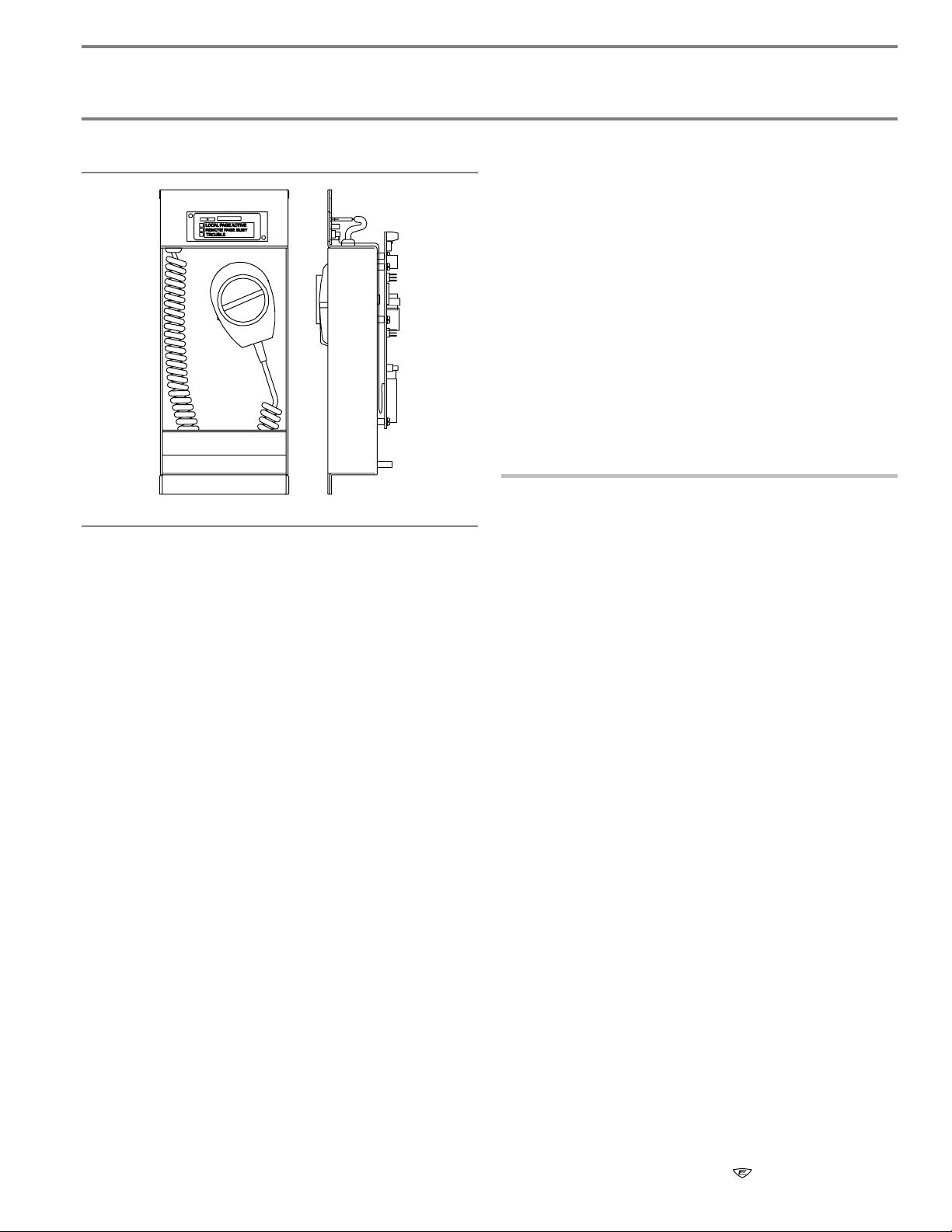
3-REMICA
Remote Microphone
Jumper settings
Jumper JP1 and JP2:
Position A: Selects AC supervision when connecting the audio
output to 3-ASU.
Position B: Selects DC supervision when connecting the audio
output to 3-REMICA.
Installation instructions
Warnings
• This product contains components that are sensitive to
static electricity. Failure to follow proper handling
procedures to prevent damage from electrostatic
discharge may result in equipment failure.
• Ensure the 24VDC riser is deenergized before making
cable connections.
To install the 3-REMICA:
FRONT SIDE
The 3-REMICA provides remote paging capability at stations
located throughout a building or campus. The 3-REMICA can
be connected to other remote microphone units to provide up
to 63 stations on the paging circuit.
The 3-REMICA occupies 2 slot positions in a 2-space, 6-space
or 10-space remote annunciator cabinet. When installed in a
cabinet with an annunciator controller, the 3-REMICA must
occupy the slot positions next to the controller.
The 3-REMICA housing assembly provides standoffs for
mounting a Signature single input module when the system
application requires electrical supervision. The 3-REMICA
trouble relay contacts change state whenever an electrical
short or open is detected on either the microphone or audio
inputs, or whenever power is interrupted to the unit.
Specifications
Power requirements
Voltage: 21 to 27 VDC
Current: 52 mA
Space requirements: 2 spaces in annunciator enclosure
Audio Output: 1 VRMS @ 400 Hz to 4 kHz
Trouble relay contacts
Current: 1 A @ 30 VDC resistive
UL rating: Common
Wiring
Termination: All wiring connects to terminal block
Size: 14 AWG (1.5 sq. mm) max.
Resistance: 210 Ω max.
Capacitance: 1 µF
Operating environment
Temperature: 32 to 120°F (0 to 49°C)
Humidity: 93% noncondensing
1. Remove the top module retainer bracket on the inner door
of the remote annunciator enclosure.
2. Loosen the bottom module retainer bracket.
3. Insert the bottom of the 3-REMICA into the bottom module
retainer bracket next to the annunciator panel controller.
4. Tilt the 3-REMICA forward until the top touches the inner
door.
5. Tighten the bottom module retainer bracket.
6. Secure the top module retainer bracket to the inner door.
7. Connect the cable assembly from P3 on the annunciator
panel controller to P4 on the 3-REMICA.
Installation Sheet 05SEP07 P/N: 387466 REV: 3.0
3-REMICA - Remote Microphone 1 / 2

Wiring diagrams
To Audio Source Unit or
next Remote Microphone
Unit [1] [3]
AUDIO OUT
From secondary
24VDC riser
From primary
24VDC riser
1 2 3 4 5 6 7 8 9 1011121314151617181920
TB1
Place jumper to position A when
audio output is connected to an
Audio Source Unit input.
Place jumper to position B when
audio output is connected to the
Remote Microphone input.
KEY OUT
JP2
B
A
JP2
B
A
AUDIO IN
KEY IN
From Remote Microphone [2] [3]
AUDIO IN
KEY IN
From Remote Microphone
[2] [3]
NC
To trouble relay
C
interface circuit
NO
JP1
Place jumper to position A when
B
audio output is connected to an
Audio Source Unit input.
A
JP1
Place jumper to position B when
B
audio output is connected to the
Remote Microphone input.
A
To next annunciator strip
Notes
[1] Power-limited and supervised.
[2] Terminate the KEY IN input with a 1.8 k EOL resistor when it is not used.
Ω
[3] Wiring must be enclosed in conduit.
Figure 1: Field wiring for the 3-REMICA
3-REMICA
Support standoffs for
mounting Signature module
TB1-19
TB1-20
FROM
PREVIOUS
DEVICE
DATA IN (-)
From annunciator controller
Signature Single Input Module
(Personality Code 3)
DATA OUT (+)DATA IN (+)
DATA OUT (-)
TO
NEXT
DEVICE
Figure 2: Trouble relay interface circuit wiring
P/N: 387466 REV: 3.0 05SEP07 Installation Sheet
2 / 2 3-REMICA - Remote Microphone
 Loading...