

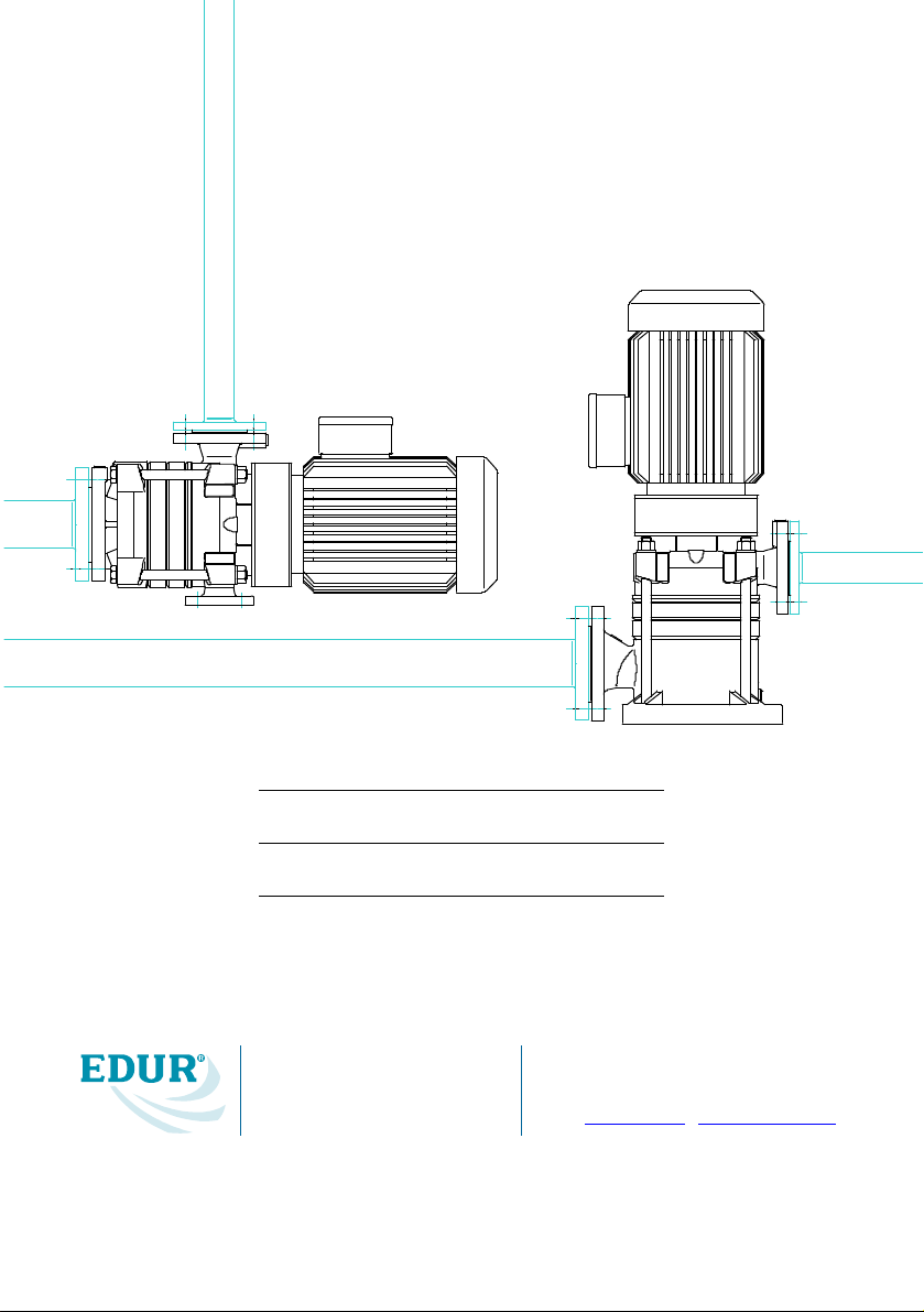
Operating Instruction
Segmental Type Pumps
Please keep your Operating Instruction in a safe place!
Type
Serial No.
EDUR-Pumpenfabrik
Eduard Redlien GmbH & Co. KG
E-mail: info@edur.de · http://www.edur.de
Postfach 1949 · D-24018 Kiel
Tel. (+431) 689868 · Fax (+431) 6898800

2
Contents
1 Security 3
1.1 Identification of Safety Instructions in the
Operating Manual 3
1.2 Qualification and Training of Operating
Personnel 3
1.3 Hazards in the Event of Non-Compliance
with the Safety Instructions 3
1.4 Compliance with Regulations Pertaining to
Safety at Work 4
1.5 Safety Instructions relevant for Operation 4
1.6 Safety Instructions relevant for Maintenance,
Inspection and Assembly Work 4
1.7 Unauthorized Alterations and Production of
Spare Parts 4
1.8 Unauthorized Modes of Operation 4
2 Transport and Intermediate Storage 4
2.1 Transport 4
2.2 Intermediate Storage 5
2.2.1 Internal Preservation 5
2.2.2 Preservation Control 5
2.2.3 Removal of Preservation 5
3 Description 5
3.1 Design 5
3.2 Place of Operation 6
4 Mounting 6
4.1 Installation 6
4.2 Connected Loads 6
4.3 Direction 6
4.4 Coupling Protection 7
4.5 Piping 7
4.5.1 General Remarks 7
4.5.2 Suction Pipeline 7
4.5.3 Pressure Pipeline 7
4.5.4 Additional Connections 7
4.6 Low-Noise Installation 7
5 Starting Operation/ Stopping Operation 7
5.1 Preparations for Initial 7
5.2 Initial Starting 7
5.3 Restarting 8
5.4 Stopping Operation 8
6 Service/Maintenance 8
6.1 Supervision of Operation 8
6.1.1 Shaft Bearing 8
6.1.2 Mechanical Seal 8
6.1.3 Gland Packing 8
6.2 Maintance 9
6.2.1 Preparation 9
6.2.2 Dismounting 9
6.2.2.1 Pump 9
6.2.2.2 Dismounting of Mechanical Seal 9
6.2.2.3 Motor 9
6.2.3 Mounting 9
6.2.3.1 General Remarks 9
6.2.3.2 Mounting of the Motor 10
6.2.3.3 Replacing the Gland Packing 10
6.2.3.4 Mounting of Mechanical Seal 10
7 Disturbance 12
8 Pump View and List of Spare Parts 13
8.1 LBU 13
8.1 VBU 14
3
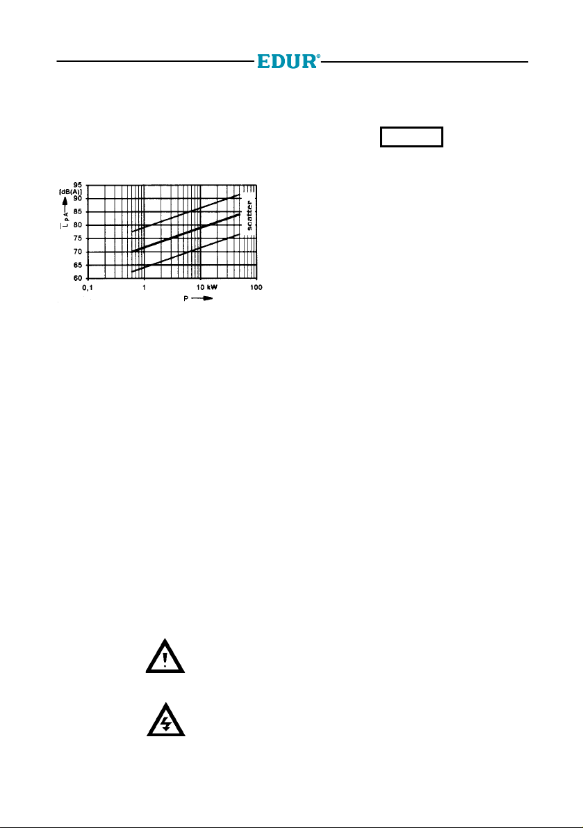
General
The most important operational data are
mentioned on the type label. The sound
pressure L
depending on the nominal pump power input P
will be seen from the diagram underneath.
Fig. Noise emission
The actual sound level ascertained at place of
installation will possibly differ considerably from
these values due to the operating conditions and
the conditions of installation.
following VDI-guidelines 3743 sheet 1
pA
1 Security
This operating manual gives basic instructions
which are to be observed during installation,
operation and maintenance of the pump. it is
therefore imperative that this manual be read by
the responsible personnel/operator prior to
assembly and commissioning. It is always to be
kept available at the installation site.
It is not only the general safety instructions
contained under this main heading safety that are
to be observed but also the specific information
provided under the other main headings.
1.1 Identification of Safety
Instructions in the Operating
Manual
Safety instructions given in this manual
non-compliance with which would affect safety are
identified by the following symbol:
or where electrical safety is involved, with
see DIN 4844-W9
Instructions non-compliance with which would
give rise to malfunctioning of the machinery are
identify by the word
CAUTION
It is imperative that signs affixed to the machine,
e. g.
- arrow indicating the direction of rotation
- symbols indicating fluid connections
be observed and kept legible.
1.2 Qualification and Training of
Operating Personnel
The personnel responsible for operation,
maintenance, inspection and assembly must be
adequately qualified. Scope of responsibility and
supervision of the personnel must be exactly
defined by the plant operator. If the staff does not
have the necessary knowledge, they must be
trained and instructed, which may be performed
by the machine manufacturer or supplier on
behalf of the plant operator. Moreover the plant
operator is to make sure that the contents of the
operating manual are fully understood by the
personnel.
1.3 Hazards in the Event of
Non-Compliance with the Safety
Instructions
Non-compliance with the safety instructions may
produce a risk to the personnel as well as to the
environment and the machine and results in a
loss of any right to claim damages.
For example, non-compliance may involve the
following hazards:
- Failure of important functions of the
machine/plant
- Failure of specified procedures of
maintenance and repair
- Exposure of people to electrical, mechanical
and chemical hazards
- Endangering the environment owing to
hazardous substances being released
see DIN 4844-W8
4
1.4 Compliance with Regulations
Pertaining to Safety at Work
When operating the pump, the safety instructions
contained in this manual, the relevant national
accident prevention regulations and any other
service and safety instructions issued by the plant
operator are to be observed.
1.5 Safety Instructions relevant for
Operation
-
If hot or cold machine components involve
hazards, they must be guarded against
accidental contact.
- Guards for moving parts (e.g. coupling)
must not be removed from the machine
while in operation.
- Any leakage of hazardous (e.g. explosive,
toxic, hot) fluids (e.g. from the shaft seal)
must be drained away so as to prevent any
risk occurring to persons or the environment.
Statutory regulations are to be complied
with.
- Hazards resulting from electricity are to be
precluded (see, for example, the
VDE Specifications and the bye-laws of the
local power supply utilities).
1.6 Safety Instructions relevant for
Maintenance, Inspection and
Assembly Work
It shall be the plant operator's responsibility to
ensure that all maintenance, inspection and
assembly work is performed by authorized and
qualified personnel who have adequately
familiarized themselves with the subject matter by
studying this manual in detail.
Any work on the machine shall only be performed
when it is at a standstill, it being imperative that
the procedure for shutting down the machine
described in this manual be followed.
Pumps and pumps units which convey hazardous
media must be decontaminated.
On completion of work all safety and protective
facilities must be re-installed and made operative
again.
Prior to restarting the machine, the instructions
listed under Initial commissioning are to be
observed.
Unauthorized Alterations and Production of Spare
Parts
Any modifications may be made to the machine
only after consultation with the manufacturer.
Using spare parts and accessories authorised by
the manufacturer is in the interest of safety. Use
of other parts may exempt the manufacturer from
any liability.
1.7 Unauthorized Modes of
Operation
The reliability of the machine delivered will be only
guaranteed if it is used in the manner intended, in
accordance with our order documentation,
especially with the order confirmation.
The limit values specified in the data sheet must
under no circumstances be exceeded.
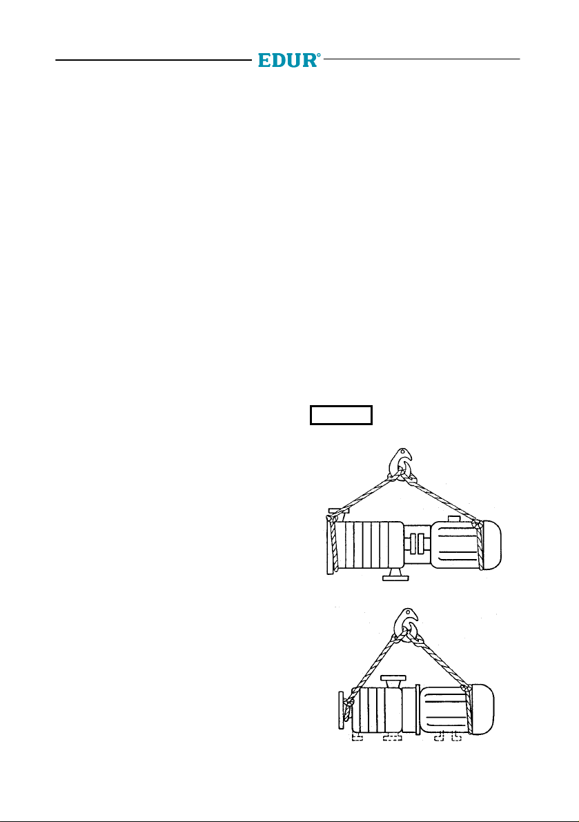
2 Transport and Intermediate Storage
2.1 Transport
When transporting the complete pump unit by
crane, mount the ropes as shown in the figure.
The crane facility and the ropes must be of
CAUTION
for transport of the complete pump unit.
Fig. 2.1a Pumps of structural form V
sufficient capacity. The ring loop
of the motor must not be used
Fig. 2.1b Pumps of structural form L
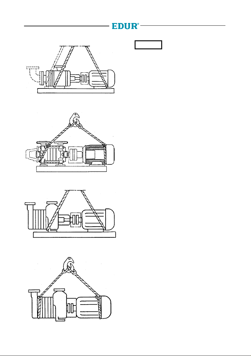
5
Fig. 2.1c Pumps of structural forms N, S and
N1-N9
Fig. 2.1d Pumps of structural form Z
CAUTION
and base plate are tightened at our works. Please
take care that before setting into operation the
screws have to be released by all means resp. in
case of a transport again have to be tightened.
In this regard also see section 4.1
For transport only the screws
between foot of suction casing
2.2 Intermediate Storage
On delivery, all pumps are preserved. Thus, they
can be stored for 6-12 months. If the storage time
is longer or the pumps are not in operation, they
must receive additional preservation on the inside.
The preservation means (please consult us)
depends on the used materials and conditions of
operation.
The storage room must be roofed and well
ventilated. Avoid temperatures below zero and
high humidity.
2.2.1 Internal Preservation
Close the suction branch securely. Fill the pump
with the preservation means and slowly turn the
rotor manually. Close the pressure branch
securely.
2.2.2 Preservation Control
Check the filling level of the pump and turn the
rotor by hand at regular intervals of 3 months.
Refill preservation means, if necessary.
Fig. 2.1e Pumps of structural forms V1-V6, E1-E6,
E11-E16
Fig. 2.1f Pumps of structural forms
NVB(K)1-NVB(K)9, V1-V6, E1-E6,
E11-E16, NuV25
2.2.3 Removal of Preservation
Prior to operation, the pump must be rinsed
thoroughly. In the case of additional preservation,
the preservation means on the inside must at first
be removed.
3 Description
3.1 Design
Horizontal and vertical, single-stage or multi-stage
ring section pumps, with or without an electric
drive unit, on a common bed-plate or unitconstruction pumps, available in different
construction materials, sizes and with different
shaft sealings.
Self-priming pumps are provided with an inlet
bend fitted at the suction branch.

6
3.2 Place of Operation
The pump unit must be freely accessible for the
purpose of supervision, servicing, maintenance,
mounting and dismounting.
Avoid using it in corrosive and very dusty
surroundings.
The limiting values of the electric drive unit with
regard to the insulation material class and the
types of protection must be observed.
For other drive units supplied, see the enclosed
separate operating instructions.
4 Mounting
4.1 Installation
The complete pump unit is generally mounted on
a pedestal. The pedestal must be even and must
have fasteners and a sufficient load capacity.
Instead of the pump being secured by means of
fasteners, the bed-plate of horizontal pumps or
the suction casing of vertical pumps can be
sealed in the pedestal by a depth of about 20 mm.
The complete pump unit must be adjusted by
means of a spirit level when it is being mounted
on the pedestal. The levelling plates are to be
installed between the bed-plate or suction casing
and the pedestal as well as close to any existing
fasteners. All levelling plates must be well set.
The fasteners must be tightened steadily after the
complete pump unit has been adjusted.
In the case of self-priming pumps, the pipe bend
must not be removed or distorted.
CAUTION
plate, the coupling must be checked thoroughly
after the piping has been connected and the
bed-plate secured. If necessary, pump and motor
must be readjusted.
When checking the coupling and adjusting the
unit, first loosen the pump footings and then
retighten them but without stresses.
CAUTION
the suction casing must never be screwed to the
bed-plate in order to avoid axial distortion.
Pump and motor are correctly adjusted if the
distance between a straight-edge which is placed
on the coupling halves and the relevant shaft is
the same for the entire circumference of the shaft.
The coupling rubber must have free motion of
1 to 2 mm between the coupling halves for the
entire circumference on both sides (Fig. 4.1a).
Even if the pump unit is delivered
completely mounted on the bed-
If the pump has two pump
footings, the pump footing below
Fig. 4.1a Adjustment of the Coupling
The permissible axial and radial deviation
measured at the front end and the circumference
of the coupling is 0.1 mm. If this is not the case,
the pump unit of the motor must be readjusted.
Subsequently, the motor footing must also be
tightened without stresses and the adjustment of
the coupling must be checked once again.
CAUTION
shaft and shaft sealings.
Errors in adjustment can
increase the load on the bearing,
4.2 Connected Loads
Work must only be executed when
electricity is switched off. Make sure
that the system cannot be powered
on accidentally.
CAUTION
pumped liquid. The pump must by no means be
operated without liquid!
The pump must be connected according to
international national requirements as well as
according to the requirements of the local mains
system. Voltage and frequency must correspond
to the winding of the electric drive. For details of
the respective winding, see the type label.
The motor must not be operated without motor
protection facility.
For motors with explosion protection, the range of
temperature of the motor indicated on the type
label must correspond to the range of the fuel
gas.
Prior to connecting the pump to
the power system, fill it with
4.3 Direction
Switch on the motor briefly in order to check the
direction of rotation. The motor must not reach its
operational speed. The direction of rotation must
correspond to the arrow indicating the direction of
rotation on top of the pump. If the direction of
rotation is not correct, perform the relevant
modifications at the phase-sequence.

7
4.4 Coupling Protection
The pump must not be operated if
coupling protection is not fitted. If this
coupling protection is not supplied by
the manufacturer, the operator of the pump must
supply it himself.
4.5 Piping
4.5.1 General Remarks
The nominal widths of the pipes must be at least
as wide as those of the pump connection joints.
For adapters, use extension angles of 8°, if
possible.
The pipes must be gathered and secured right in
front of the pump so that their weight does not
affect the pump. The negative effects of variations
in temperature and occurring oscillation may be
reduced by installing a suitable bellow expansion
joint (see section 4.6).
Measuring equipment for supervision of the pump
operation is required.
Prior to operation, all parts in contact with liquids
must be thoroughly cleaned.
4.5.2 Suction Pipeline
The suction pipeline must be as short as possible.
Variations in diameter and additional piping must
be kept to a minimum. The suction pipeline
towards the pump must be rising, the inlet must
be descending to prevent an air pocket from being
formed. For non-self-priming pumps, installation
of a foot valve into the suction pipeline is
compulsory in order to avoid that, in case of a
standstill, the pump and the suction pipeline run
out of liquid during suction operation.
Contamination of the pumped liquid is to be
avoided by using a suction hose or a filter. By no
means must air penetrate through the liquid level
via the suction hose or dirt be whirled up from the
liquid pool. Clean the suction hose and filter
regularly.
To close the suction pipeline in the case of
mounting or maintenance work, a stop valve must
be provided near the pump. The stop valve must
not be used for adjustment and must be
completely open during operation.
4.5.4 Additional Connections
For the position and dimension of required
additional connections as e.g. for rinse, stop and
quench liquid, refer to the labels supplied with the
pump or to the drawings in the operating
instructions. The rinse, stop and quench liquids
must be checked at regular intervals.
Connections for ventilation and release of the
leakage liquid are also described in the drawings.
4.6 Low-Noise Installation
A reduction in noise (Fig. 4.6a) can be achieved
by isolating the pedestal (1) from the ground by
means of an appropriate insulation board (2) and
by using suitable bellow expansion joints between
the piping and the pump. The pedestal (1) must
not be secured to the ground or to the walls.
Fig. 4.6a Low-Noise Installation
Another possibility to reduce the noise is the use
of oscillation absorbers. In this case, you need to
install a frame under the base of the pump.
Bellow expansion joints must be
checked regularly for brittle and
cracks.
5 Starting Operation/ Stopping
Operation
5.1 Preparations for Initial
Prior to the start, the pump and the suction
pipeline must be drained of air and be completely
filled with the pumped liquid. The stop valve in the
suction or inlet pipeline must be completely open,
if there is one. For self-priming pumps, the pump
must only be completely drained of air and filled
with the pumped liquid.
4.5.3 Pressure Pipeline
For adjustment, repair and mounting of the pump,
a stop valve is to be provided near the pressure
joint.
5.2 Initial Starting
The pump must not be started until the outlet stop
valve is closed so as to avoid overload of the
motor. Immediately after reaching the operational
speed, slowly open the stop valve of the pressure
pipeline and adjust the operating point.

8
Until the liquid starts moving against atmospheric
pressure, the hydrostatic pressure for self-priming
pumps must not exceed 1 bar with reference to
the difference in height between suction and
outlet liquid level and to the density of the pumped
liquid.
The pump must never be operated for
a longer period if the outlet stop valve
damaged if the pumped liquid exceeds the
permitted temperature.
is closed. The pump unit will be
5.3 Restarting
Do not restart the pump until the pump shaft
stands still.
CAUTION
rotation of the pump. If this is the case,
mechanical seals dependent on direction of
rotation may be damaged.
Backflow of liquid must not result
in a change of direction of
5.4 Stopping Operation
Close stop valve of the pressure pipeline. If there is
a backflow stop and sufficient counter pressure in
the pipeline, the stop valve can remain open.
Switch off the motor and observe that it slows down
smoothly. Close stop valve of the pressure pipeline.
If the pumped liquid reaches temperatures below
zero and/or if longer periods of standstill occur,
the pump must be drained completely and be
preserved (see section 2.2.1).
6 Service/Maintenance
6.1 Supervision of Operation
Ensure that the pump runs free of vibration and
smoothly
The pump must by no means be operated without
liquid.
There is only a minimal or invisible loss of leakage
(steam) if the mechanical seals function correctly.
Gland packings should drip slightly.
Do not operate the pump for a longer period with
a closed stop valve.
The maximum permitted environmental
temperature is 40oC. The storing temperature
measured at the motor or pump casing may
exceed the environmental temperature by 50oC. It
must not exceed 90oC. Only operate the pump at
a higher temperature with the manufacturer's
approval.
We have to point out that an increased wear may
occur in case of transport of abrasive / corrosive
media.
CAUTION
components have to be checked regularly in order
to detect wear in time - before a damage occurs.
The intervals have to comply with the liquids to be
pumped and initially have to be carried out more
frequently, until perceptions about the progress of
wear are attained.
Installed pumps must be powered on and off
briefly once a week in order to guarantee that they
are ready for operation.
In case of corrosive / abrasive
media to be pumped pressurized
6.1.1 Shaft Bearing
Under normal operation conditions, replace the
motor bearings after 20.000 hours of operation or
at the latest after 2,5 years. In the case of bad
operation conditions, as e.g. a high environmental
temperature or a corrosive and dusty
environment, the motor bearings must be checked
at an earlier date and, if necessary, be replaced.
Pump bearings with a lubrication device must be
checked every 5000 hours of operation. Dirty
bearings must be cleaned and filled with new
lubricant. The free space in the bearing and
casing should be filled by 30-50% with lubricant.
Do not use resinous or acid lubricants. Its
consistencies (NLGI grade) should correspond to
a worked penetration of 265 to 295 mm/10.
Lithium-base soap lubricants with a drop point of
more than 185°C are to be used for pumped
liquids which have a maximum temperature of
110°C. For pumped liquid with a higher
temperature, use silicon lubricants with a lithiumbase soap and with a drop point of more than
215°C.
If necessary, the bearings can also be lubricated
with lubricants of a different soap base. For this
based on different soaps must not be mixed. The
required re-lubrication periods must then be
adapted to the type of lubricant used.
6.1.2 Mechanical Seal
The mechanical seals are maintenance-free. If
leakages occur after a longer period of operation,
replace the complete seal.
6.1.3 Gland Packing
Gland packings are low-maintenance parts and
must leak slightly during operation. Do not tighten
a gland packing after its first operation.
Considerable leakage at the beginning disappears
by itself.
If greater leakages occur during operation, the
gland lid or insert must be slightly tightened,
however it must never be tightened at a slant.

9
It must be possible to rotate the slide slightly after
having tightened the lid or insert. If tightening of
the gland lid or insert results in the pump being
heated excessively or if it is not possible to tighten
the gland lid or insert any further, the gland
packing must be replaced completely.
CAUTION
If the gland lid or insert is
tightened too much the shaft will
be damaged.
6.2 Maintenance
6.2.1 Preparation
In order to make sure that the pump
cannot be started, separate the power
cable from the motor. Secure the unit
against accidental switch-on.
Close the stop valve of the pressure and suction
pipelines. The pump casing must have reached
the environmental temperature and be drained of
liquid and pressure. In the case of pumps in
unit-construction with mounting flange, the
container must be drained completely.
6.2.2 Dismounting
By no means use force while dismounting the
pump.
Proceed as follows for the different pump types:
Unit-construction pumps:
- Separate the pump from the piping and any
additional connections
- Loosen the fasteners
Pumps with a motor on a common bed-plate:
- Separate the pump from the piping and any
additional connections
- Remove the coupling protection
- Loosen the pump from the bed-plate and
remove it from the motor
For fixed parts of the casings, impellers and
couplings, use appropriate dismounting facilities.
Impellers, which cannot easily be removed from
the shaft, can be pushed back from the shaft by
means of two hexagon screws.
6.2.2.1 Pump
The pump is always dismounted on the suction
side and with the shaft in a horizontal position.
Refer to enclosed drawings on page 13 to 14
(only pumps of structural forms LBU and VBU) or
in the supplementary sheet for the dismounting
sequence.
For unit-construction pumps, the pump and motor
must not be separated for the axial fixing of the
pump shaft.
To prevent the partially mounted pump or the
complete pump unit from tilting, put blocks as a
mounting aid under the step casing and, if
necessary, under the drive unit.
Mark the position and sequence of the pump parts
for later mounting.
6.2.2.2 Dismounting of Mechanical
Seal
In order to replace the mechanical seal, the pump
must be dismounted (s
ee Fig. 6.2.2) first. After that the pump must be
dismantled before the seal can be removed.
Dismantle the pump in the sequence shown in the
exploded view diagrams, pages 13 or 14. Remove
impeller (230), casing (108,117), key (940.1) and
the circlip (932), pull the delivery casing (107) off
the shaft with the mechanical seal (433).
6.2.2.3 Motor
For vertical pumps and unit-construction pumps, it
is not necessary to dismount the pump unit. The
pump can remain in the piping. First, remove the
coupling protection and loosen the hexagon
screws of the coupling. After having loosened the
hexagon screws at the motor flange, remove the
motor from the pump.
For pumps with a motor on a common bed-plate,
first remove the coupling protection. Then, loosen
the mounting screws of the motor and separate
the motor from the pump.
6.2.3 Mounting
6.2.3.1 General Remarks
Prior to mounting, all parts must be cleaned
thoroughly. Remove remaining parts of the seals.
Slight scratches and grooves on the shaft near
the shaft seal and on other sealing surfaces of the
casings are to be polished with linen.
CAUTION
damage and replace them, if necessary.
Mounting is effected in the reverse order of
dismounting. Heat up the coupling joints of rigid
couplings to approximately 250°C prior to
mounting them onto the shaft.
In the case of flexible
on the pump shaft must be tightened thoroughly
If this is not possible, replace the
parts. Gaskets must always be
renewed. Check O-rings for
couplings, the coupling half

10
by means of the shaft nut and/or the hexagon nut.
If this is not observed, the bearings will be
damaged.
The starting torques for the tie bolts and locking
screws non lubricated condition are displayed in
fig. 6.2.3.1a.
thread M 10 M 12 M 14 M16 M20
torque
Nm
* for pumps with more than 4 tie bolts
Abb. 6.2.3.1a Starting torque
30 40 50 110
70*
120
6.2.3.2 Mounting of the Motor
For initial mounting of motor and pumps with rigid
coupling, first of all, remove the transport
safeguards of the lantern or of the intermediate
flange, then remove the motorside coupling half.
Subsequently, put this part onto the motor shaft.
This coupling half must be next to the motor shaft
collar. Tighten screws, join motor and pump
centrically without tilting them. Tighten screws
between motor and lantern or intermediate flange
and then coupling screws.
CAUTION
are connected and the motorside or pumpside
coupling half has been installed incorrectly or not
at all.
The inner parts of the pump will
be damaged if motor and pump
6.2.3.3 Replacing the Gland Packing
Remove gland lid or insert and remove the old
packing rings. Clean gland packing compartment
of any remaining packing material. Insert new
gland packing, ring by ring with staggered open
butt joint, see Fig. 6.2.3.3a and slightly tighten it
with gland lid or insert. No lubricant must touch
the gland packing.
6.2.3.4 Mounting of Mechanical Seal
CAUTION
carefully and with precision.
Do not touch the surfaces of the seal. Do not
damage the sealing parts. To facilitate the
mounting, moisten elastomer with low-surface
tension water.
The shape of spare mechanical seals may differ
from those of the installed mechanical seal.
However, the dimensions of the spare mechanical
seal are the same and for that reason it can be
replaced.
To avoid distortion of the counter-ring, mechanical
seals with doubled PTFE-wrapped sealing O rings
are additionally secured by a leading pin inside
the casing. The pin must be removed when
replacing the type of mechanical seals and when
using a type with different O-ring material.
For details of the individual types of mechanical
seals observe the following procedures.
When mounting the mechanical
seals, you must proceed very
Mechanical seals and sealingparts
with elastomer made of EP rubber
must by no means come in contact
with oil or grease.
Fig. 6.2.3.3a Gland packing
During the first hours of operation, watch out for
any considerable increase in heat or leakage.

11
Observe the enclosed, separate mounting
instructions for those types of mechanical seals
which are not listed.
1. Stressed mechanical seal independent of
direction of rotation with elastomer bellows
(fig. 6.2.3.4a)
Fig. 6.2.3.4a
Carefully press angle collar (1) together with
counter ring (2) into the counter ring fit.
Twist the rotating unit (3,4,5) onto the shaft
as far as the counter ring. Put on supporting
ring and mount circlip (932*) and/or push
shaft sleeve for mechanical seal (516*) onto
the shaft.
For suction-side mechanical seals (only
pumps of type Z), mount circlip (932.1*).
Push rotating unit (5,4,3) on to the shaft up
to the circlip (932.1*).
2. Stressed mechanical seal dependent on
direction of rotation with conical springs
(fig. 6.2.3.4b)
Fig. 6.2.3.4b
Insert O-Ring (1) into counter ring fit and
carefully press counter ring (2) into it. Push
mechanical seal (3) onto the shaft as far as
the counter ring. Press O Ring (4) into the
mechanical seal by means of the supporting
ring. The pivot of the pressure spring (6)
must be situated in the groove of the
mechanical seal ring. Put on locking
ring (7). Mount circlip (932*) and/or shaft
sleeve for mechanical seal (516*).
For suction-side mechanical seals (only
pumps of type Z), mount circlip (932.1*).
Push locking ring (7), pressure spring (6),
supporting ring (5), O ring (4) and
mechanical seal ring (3) separately onto the
shaft.
*
see sectional drawing in the operating
instruction (only pumps of structural
forms LBU and VBU) or sectional
drawing in supplementary sheet.

12
7 Disturbance
Pump is blocked
Coupling fault
Heads too low
Rates of flow too low
Bearing temperature too high
Pump operates badly
Leakages at the casing
Overload of the drive
Shaft seal leaks badly
z z
z z z
z
z
z z
z
z z
z
z
z
z
z
z
1)
Please consult us
2)
Only pumps with lubricator
z z z
z z
z z z
z z
z z
z z z
z z
z z
z
z z
z z
To eliminate disturbance, the pump must have
CAUTION
reached the environmental temperature and must
be drained of air and pressure.
The chart shows a list of potential errors and their possible causes. For
errors which are not listed here or which have other reasons, please
consult us.
Motor protection activated
Pump is becoming too hot
Cause Elimination
Pump and/or suction pipeline is not
completely drained of air/filled
Suction level too high, NPSH value of
the unit too high
z
Air inclusion in the pumped liquid too
high
z
Formation of air bag in suction pipeline Change suction pipeline/attach drain valve
z
Direction of rotation incorrect Check and change phase sequence, if
Rates of flow too low Readjust operating point
z
Wear of inner parts Replace inner parts
Pump operates out of tolerance Readjust operating point
Shaft seal damaged Replace shaft seal
Stuffing box gland jammed or tightened
too heavily
Air entry through shaft sealing on
suction side
Speed too low Increase speed
Speed too high Reduce speed
Connecting screws, seals Tighten connecting screws, replace seals
Pump/motor not adjusted Replace defective parts, adjust pump/motor
Problems via piping Check pipe connections/pump
Insufficient, excessive or wrong
lubrication grease
Incorrect coupling gap Readjust motor
Defective bearing Replace bearing
Density/viscosity of pumped liquid
higher than indicated in the order
Motor protection unit set incorrectly or
defective
Impeller blocked Clean interior parts from particles and
Drain of air and fill
Completely open stop slide in the suction
pipeline, check suction bag/footing valve, if
necessary, increase liquid level, if
necessary
Seal suction pipeline once again, check
suction bag, increase liquid level, if
necessary
necessary
Correct
Check liquid sealing or replace packing
1)
1)
fasteners/bearing distance of pipe clips,
installation with oscillation absorbers
Add, remove or change grease2)
1)
Check motor protection unit, replace it, if
necessary
impurities

y
13
210 932.1 844
341 681 901.2 844.1 904
903
117108
920 nut
930/.1-.2 tooth lock washer
932/.1 circlip
940/.1 ke
When ordering spare parts, please
indicate serial no., type no. and
parts no. by all means.
904940 930.1 901.1
901.4
part no. designation 903 screwed plug
904 hexagon socket set screw
905 tie bolt
B
C
411 903 722554.1 901 930.2
part no. designation 554/.1 washer
592/.1 base
681 coupling guard
930
412
412 592 182 531 901.3
part no. designation 230 impeller
341 lantern
411 joint ring
722 intermediate flange
844/.1 disc type coupling
412 o-ring
433 mechanical seal
901/.1-.5 hexagon screw
531/.1 locking sleeve
545
A
930 531.1 412
A: Screwed plug G¼ for vent connection and pressure gauge connection
8 Pump View and List of Spare Parts
8.1 LBU
905 411 903 106 230 940.1 230 940.1 932 433 107 554 920 411
592.1 182.1901.5
part no. designation 106 suction casing
107 delivery casing
108 stage casing
117 endstage casing
182/.1 foot
B: Screwed plug G¼ for vent connection and pressure gauge connection
210 shaft
C: Screwed plug G¼ for drain

14
p
y
901.1930.1940 904
all means.
901.2 210 932.1 844 844.1 904
341 681
903
920 411
107 554
901.4
part no. designation 930/.1 tooth lock washer
932/.1 circlip
940/.1 key
930.2901554.1 722903411
When ordering spare parts, please
arts no. b
indicate serial no., type no. and
B
C
part no. designation 722 intermediate flange
844/.1 disc type coupling
901/.1-.3 hexagon screw
903 screwed plug
904 hexagon socket set screw
905 tie bolt
920 nut
412412
part no. designation 341 lantern
411 joint ring
412 o-ring
433 mechanical seal
554/.1 washer
230 230 433
412
681 coupling guard
905411
903 940.1 108 117940.1 932
106
545
C
part no. designation 106 suction casing
107 delivery casing
108 stage casing
8.2 VBU
117 endstage casing
B: Screwed plug G¼ for vent connection and pressure gauge connection
210 shaft
230 impeller
C: Screwed plug G¼ for drain

15
As defined by machinery directive 98/37/EC Annex II A
Declaration of Conformity
Herewith we declare that the pump unit supplied with mounted electric drive
complies with the following provisions applying to it
EC-machinery directive (98/37/EC, Annex I No. 1)
EC-low voltage directive (73/23/EEC)
Applied harmonized standards
EN 809 EN 953
EN 292-1 EN 60204-1 section 16
EN 292-2 EN 60034-5
EN 294
In case of a modification of the pump unit without being coordinated with us this declaration will not longer be
valid.
i.A.
(QM-Supervisor)
1) other driving motor see separate declaration of c onformity
1)
As defined by machinery directive 98/37/EC, Annex II B
Herewith we declare that the pump supplied without driving motor is intended to be incorporated into
machinery or assembled with other machinery to constitute machinery covered by this directive and must not
be put into service until the machinery into which it is to be incorporated has been declared in conformity with
the provisions of the directive, version 98/37/EC.
Applied harmonized standards
In case of a modification of the pump without being coordinated with us this declaration will not longer be
valid.
i.A.
(QM-Supervisor)
Declaration by the manufacturer
EN 809
EN 292-1
EN 292-2

BE1 17102,8 / 071001
 Loading...