

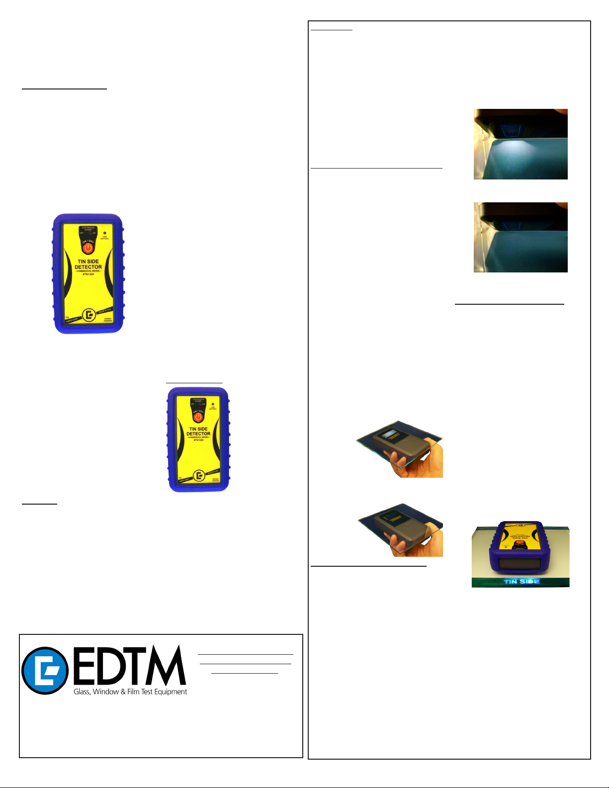
TIN SIDE DETECTOR
Commercial Model for Float Glass
GENERAL DESCRIPTION
During the production of oat glass, one
side of the molten glass comes into contact
with a bath of molten tin. Traces of tin or tin
oxide metal are deposited on the surface
of glass as it is removed from the molten
tin bath. This surface of the glass is identied as the “TIN SIDE” surface of the glass.
The opposite side of the glass is denoted
as the “AIR SIDE”. The presence of the tin
is invisible to the human eye. Glass processors nd it benecial to know which surface
of the glass is the tin side surface, since the
tin side of the glass results in a smoother
surface (among other reasons).
The TS1320 Commercial Tin Side Detector is very helpful in identifying the tin side.
Short-wave UV energy causes the tin to
uorescence at a frequency that is visible
the human eye. When the lamp is placed
on the tin side surface, the tin will uoresce
and produce a milky white image that is
visible to the human eye. If you place the
lamp on the non-tin side of the glass, the lack
of tin results in no uorescence and therefore only the duller image of the UV lamp
is seen. Since the oat glass substrate
does not transmit the UV light, the tin coating on the opposite side of the glass is not
exposed to the UV energy, and therefore it
will only uoresce when the lamp is placed
on the tin side of the glass.
WARNING: Do not expose eyes and skin to
shortwave ultraviolet light, as rays are harmful to unprotected eyes and skin. Never view
the image of the lamp directly without placing a piece of glass between your eyes and
the lamp. We recommend the user wear the
UV Blocking safety glasses supplied with
the product. UV light is not visible to the
human eye. Although the UV lamp may appear dim, recognize that this is only a small
percentage of the intensity being emitted
by the lamp. Your eyes cannot detect the
full intensity of the short-wave UV lamp.
745 Capital Commons Drive
Toledo, Ohio 43615 USA
PHONE: (419) 861-1030
FAX: (419) 861-1031
www.EDTM.com
© Copyright 2012 Electronic Design to Market, Inc. All rights reserved.
Email: sales@edtm.com
MODEL# TS1320
FEATURES
Identify the tin side of oat glass using a
custom UV lamp for detection
Also works on coated glass as long as
coating does not block UV-C energy
Commercial design includes a rubber boot
for rugged applications
Patent-pending stencil projects the words
“TIN SIDE” into the edge surface of the
glass, allowing for testing in brighter environments
Bulb mounting system absorbs shock of
dropping the unit, better than previous
competing models
Drop tested to withstand falls up to ve
feet
Momentary power switch allows user to
pulse the power to see the tin side glow
much easier, plus helps conserve life of
batteries
Slide switch also included for extended
use of the lamp
Low Battery indicator
Powered by only three-AA batteries (in-
cluded)
50% longer battery life than previous competing
Protective UV blocking safety glasses in-
cluded
Replaceable lamp option, with convenient
insertion sockets for easy replacement
Extended warranty period compared with
previous models
to
POWER SWITCH
The momentary (membrane) power switch
is the preferred switch to use for the TS
1320 product. This switch minimizes the use
of the lamp in between tests, and extends
the life of the batteries. As described later
in this operating manual, being able to
cycle the power on and off also aids in the
determination of the tin side glow.
The continual power (slide) switch should
only be used when the operator is going to
be taking repeated measurements continuously, with few breaks.
models, despite fewer batteries
glass & air space laser meters,
tempered glass detectors, SHGC,
solar, visible, & uv meters LowE- type detectors, 4 point sheet
resistance meters, tin side detectors, self-clean coating detectors,
sales kits, temperature guns &
sales kit accessories.
CONTINUAL POWER
(Slide switch)
!
!
power stays on
continuously when the
slide switch is moved to
the ON position
MOMENTARY POWER
(Membrane switch)
power only stays on
while the membrane
switch is being
depressed
KEEP THE COMPETITIVE
EDGE WITH PRODUCTS
FROM EDTM, INC.
OPERATION
You can use the TS1320 in three different
methods. You can either choose to view the
image of the lamp through the glass by placing the instrument on the bottom side of the
glass, OR you can tilt the TS1320 on the top
surface of the glass and view the reection
of the lamp under the meter OR you can
utilize the new stencil insert. You may nd
that one approach may work better for certain glass samples and various lighting conditions.
BEFORE performing any tests, we
recommend putting on the protective UV
blocking safety glasses that were supplied
with the product.
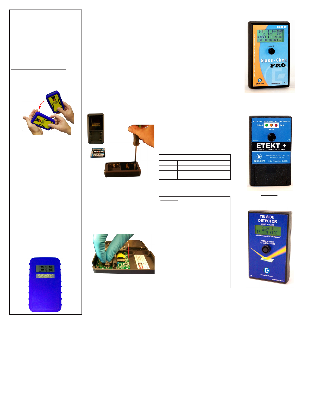
TRADITIONAL BOTTOM SIDE METHOD
To test glass using the bottom side method,
place the TS1320 on the bottom side of the
glass, as shown in Figure 1. Turn on the
power, but do not view the image of the lamp
unless it is placed behind the glass. If the
bottom side is the TIN SIDE of the glass,
the image of the lamp will appear milky white
(Figure 1). The intensity of the lamp may
even appear to get stronger. There are 2
simple ways to improve the viewing of the
glow. The rst is to use the momentary power switch on the meter to pulse the power on
and off. The pulsing power magnies the
difference between a tin side glow versus
no glow. The second method is to wave the
meter closer and further away from the glass
surface to magnify the glow differential. In
certain situations it may be easier to view
the milky white image at a slight angle.
Viewing
the image at an angle is especially
helpful when working with tinted and reective glass.
If you are on the air side of the glass, there
will be no milky white glow. The image of
the lamp will remain unchanged as shown
below.
Figure 1: Tin Side
Milky white image
(
Figure 2: Air Side (NOT Tin Side)
Dull violet lamp image
TRADITIONAL TOP SIDE METHOD
To test glass using the top side method,
place the TS1320 on the top surface of the
glass, as shown in Figure 3. Using this
method, it is important that you put on your
UV blocking safety glasses. Turn on the
power, but DO NOT look directly at the
lamp. Tilt the unit at a slight angle so you
can view the REFLECTION of the lamp.
If the reection of the lamp on the glass
appears milky white (Figure 3), then the
top surface of the glass is the TIN SIDE.
The intensity of the lamps reection may
even appear to get stronger. Again, there
are two simple ways to improve the viewing
of the glow. The rst is to use the momentary power switch on the meter to pulse
the power on and off. The pulsing power
magnies the difference between a tin side
glow versus no glow. The second method is
to wave the meter closer and further away
from the glass surface to magnify the glow
1
(
differential. In certain situations it may be
easier to view the milky white image at a
slight angle. Viewing the image at an angle
is especially helpful when working with tinted
and reective glass.
If the top surface of the glass is NOT the
TIN SIDE, then it is the AIR SIDE. The air
side of the glass will result in the lamp image
appearing normal (violet color) (Figure 4).
Figure 3: Tin Side
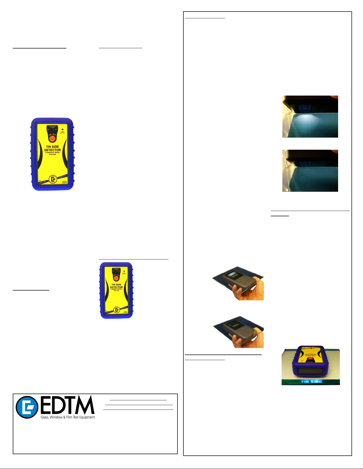
NEW STENCIL INSERT METHOD
The TS1320 design includes a patent-pending stencil insert that helps you view the tin
side glow in brighter environments. As long
as you can view the edge surface of the
glass, you can use this feature. If you do not
typically have access to the edge of the
glass surface, it may be benecial to remove
the stencil insert from the rubber boot.
The TS1320 model comes equipped from
the factory with the stencil inserted into the
rubber boot. The stencil channels the energy
from the lamp through the words “TIN SIDE”,
causing this image to be imposed on the
glass surface during tests. When the instrument is placed on the glass surface and
turned on, you will see the image of the word
“TIN SIDE” in the edge surface of the glass
if you have the meter placed against the tin
surface. YOU MUST PLACE THE METER
CLOSE TO THE EDGE OF THE GLASS SO
THE STENCILED IMAGE CAN BE TRANSFERRED FULLY TO THE EDGE SURFACE OF THE GLASS.
Milky white reection
Figure 4: Air Side (NOT Tin Side)
Dull violet lamp reection
!
Figure 5: Stenciled image on tin side of glass
Stenciled image “TIN SIDE” appears in the
surface edge when the meter is placed on
the tin side of the glass.
If you are on the air side of the glass (nontin side), the word “TIN SIDE” will NOT be
projected to the edge of the glass. It should
be noted that thicker glass will result in the
easiest viewing of the projected image.
This feature is great when you only have
access to one side of the glass, and also
when you are working in brighter light environments. Without the stencil, it is often
necessary to test the glass in a shaded or
darker environment.
OPERATION - continued
If necessary, the stencil insert can be easily removed. Simply pull the rubber boot off
the enclosure of the instrument and remove
the insert piece. (See Figure 7) Re-install
the rubber boot on the enclosure and you
will regain the full viewing window of the
TS1320 product. Store the stencil in a safe
place so it can be re-inserted at a later
date if needed.
ADDITIONAL OPERATING TIPS
1. If the instrument lamp does not turn on
instantly, tap the meter rmly against your
hand. The lamp will illuminate immediately. Please see Figure 6.
Figure 6
2. In cold temperatures, the lamp may take
a few moments to warm up to full intensity.
3. Pulsing the power with the momentary
power switch makes it easier to differentiate if there is a tin side glow or not.
4. Waving the lamp closer and then further
away from the glass, often makes it easier to see the glowing tin side image as
well.
5.
If you do not regularly have access to the
edge surface of the glass, it may be benecial to remove the stencil insert from
the lamp area. The stencil insert does
block some of the energy of the lamp.
Adding additional UV light energy to the
test subject may help improve your test
conditions. To remove the stencil insert,
it is necessary to remove the rubber boot
from the instrument rst. Simply pull the
insert out of the rubber boot and re-install on the instrument.
6. If you need to install or remove the stencil insert, please see Figure 7 for the
proper placement of the stencil in the
rubber boot.
Figure 7
LAMP REPLACEMENT
The TS1320 includes a custom short wave
UV lamp inside the enclosure. If the lamp
stops working, conrm that your batteries
are still functional. If you have replaced the
batteries and installed them correctly (double-check polarity) and the instrument is still
not working, it may be necessary for you to
replace the short wave UV lamp. The replacement lamp is PART# TS1310 and is
available from your dealer.
To replace the lamp, turn the unit off rst.
WARNING: YOU MUST REMOVE THE
BATTERIES BEFORE SERVICING THE
INSTRUMENT. There are dangerous high
voltages present inside the enclosure, and
the electronics should never be touched
when powered. Use a Phillips screwdriver
to remove the four screws of the enclosure.
Please note, two of the screws are located
behind the battery compartment cover.
two
screws
"
"
Figure 8: Remove batteries and
four screws from enclosure
!
The body of the lamp is held in place by
foam pieces, while the terminals are inserted into sockets in the circuit board. Carefully pull the old lamp out of the sockets.
Pay special attention to the foam pieces as
you may have to peel them away from the
bulb. Leave as much of the foam in place
as possible, as this helps provide shock absorption
to the bulb during use.
Figure 9: Remove the old lamp
and replace with new
The replacement bulb should never be handled with bare ngers. Please use gloves
when handling the replacement bulb. The
replacement bulb will be sent to you with the
terminals crimped at the proper location.
DO NOT MAKE ANY ADJUSTMENTS TO
THE TERMINALS, AS THEY ARE EXTREMELY FRAGILE. Carefully press the
lamp terminals into the receptacles. Fully
reassemble the unit before turning power
on to check the new lamp.
!
BATTERY REPLACEMENT
If the low battery indicator illuminates, the
instrument is warning that the batteries
should be replaced in the near future. It is
possible that the TS1320 product will continue to work for some time after the indicator illuminates. It is totally safe to continue
using the instrument while the low battery
indicator is illuminated. Monitor the intensity of the lamps to know the exact time that
the batteries need replaced. The TS1320 is
powered by three AA alkaline batteries.
Alkaline batteries are required for the best
performance of this device. Before replacing the batteries, be sure to turn the power
off. To access the batteries, you must rst
remove the rubber boot from the product.
Next you can remove the battery cover on
the back side of the enclosure by pressing
your thumb in the center of the battery cover
and sliding the removable lid off. Replace
the batteries and install the cover. Be sure
to install the batteries correctly (polarity +/-).
A battery polarity indicator is included inside
the battery compartment. Installing the batteries backwards may cause permanent
damage to the lamp and will not be covered
by the product warranty. If the unit is going
to be stored for more than a month, we recommend removing the batteries during storage.
REPLACEMENT PARTS
two
PART # DESCRIPTION
screws
TS1310 Replacement Lamp
TS1317 Replacement Rubber Boot
TS1327 Replacement Stencil Insert
WARRANTY
The manufacturer warrants the electronics included
in all models of the TS1320 to be free from defects
in material and workmanship under normal use and
service as specied within the operator’s manual. The
manufacturer shall repair or replace the unit within
twelve (12) months from the original date of shipment
after the unit is returned to the manufacturers factory,
prepaid by the user, and the unit is disclosed to the
manufacturers satisfaction, to be thus defective. This
warranty shall not apply to any unit that has been repaired or altered other than by the manufacturer. The
aforementioned provisions do not extend the original
warranty period of the unit which has been repaired
or replaced by the manufacturer. Batteries, lamps,
rubber boots, stencils and front panel interface components are not covered by warranty.
The manufacturer assumes no liability for the consequential damages of any kind through the use or misuse of the TS1320 product by the purchaser or others.
No other obligations or liabilities are expressed or implied. All damage or liability claims will be limited to an
amount equal to the sale price of the TS1320, as established by the manufacturer.
RELATED PRODUCTS
Identify location and type of low e coatings, as well
as glass & air space thickness. Good for single,
double & triple pane windows. (Model# GC3000)
“Glass-Chek PRO”
Dual Pane Low E CoatingDetector (Model# AE1601)
“ETEKT+”
DIGITAL Tin Side Detectors
(Model# TS2300)
Remember, DO NOT stare at the lamp output directly. Either look at the image through
a piece of oat glass, or put on your UV
blocking safety glasses (included).
2
DÉTECTEUR DE LA FACE ÉTAIN
Modèle Commercial pour Verre Flotté
FABRIQUÉ AUX ÉTATS-UNIS D’AMÉRIQUE
DESCRIPTION GÉNÉRALE
Pendant la production de verre otté, un côté
du verre fondu entre en contact avec un bain
d’étain fondu. Des traces d’étain ou d’oxyde
d’étain sont déposées sur la surface du verre
alors qu’il est retiré du bain d’étain fondu.
Cette surface du verre est identiée comme
étant la «FACE ÉTAIN» du verre. Le côté
opposé du verre est appelé «FACE AIR». La
présence d’étain est invisible pour l’œil humain. Les industries de traitement du verre
ont besoin de savoir quel côté de la surface
du verre est la face étain, car cette face du
verre est plus lisse (entre autres raisons).
Le détecteur commercial de face étain TS
1320 est très utile pour identier la face étain.
Les ondes courtes UV entraînent la uorescence de l’étain à une fréquence visible pour
l’œil humain. Lorsque la lampe est placée
sur la face étain, ce dernier se met à briller
et à produire une image blanc laiteux visible
pour l’œil humain. Si vous placez la lampe
sur la face sans étain du verre, l’absence
d’étain entraîne l’absence de uorescence
et de ce fait seule une image terne de la
lampe UV apparaît. Comme le substrat de
verre otté ne transmet pas la lumière UV,
le revêtement d’étain du côté opposé du
verre n’est pas exposé à l’énergie UV, de ce
fait, il entrera en uorescence lorsque la
lampe est placée sur la face étain du verre.
AVERTISSEMENT: Ne vous exposez pas
la peau ni les yeux aux rayons ultraviolets,
car ils sont nocifs pour la peau et les yeux
non protégés. Ne regardez jamais l’image
de la lampe directement sans placer du verre
entre vos yeux et la lampe. Nous vous recommandons de porter les lunettes de sécurité bloquant les UV fournies avec le produit. La lumière UV est invisible pour l’œil
humain. Bien qu’une lampe UV puisse paraître peu puissante, ce n’est qu’une petite
partie de l’intensité émise par la lampe. Votre
œil ne peut pas détecter l’intensité
des lampes à UV à ondes courtes.
745 Capital Commons Drive
Toledo, Ohio 43615 USA
TÉLÉPHONE: (419) 861-1030
TÉLÉCOPIE: (419) 861-1031
www.EDTM.com
Courriel: sales@edtm.com
Copyright 2012 Electronic Design to Market, Inc. Tous droits réservés.
MODÈLE n° TS1320
CARACTÉRISTIQUES
Identier la face étain du verre otté à l’ai-
de
d’une lampe UV personnalisée pour la
détection
Fonctionne également sur le verre avec un
revêtement, tant que ce dernier ne bloque
pas les rayonnements UV-C
Conception commerciale comprenant une
semelle en caoutchouc pour des applica-
tions industrielles
Projection des termes «TIN SIDE» sur la
surface du verre (brevet en cours) an de
permettre de réaliser des essais dans des
environnements plus lumineux
Système de montage de la lampe avec
absorption des chocs en cas de chute de
l’unité, offrant ainsi la meilleure protection
du marché
Test de chute jusqu’à une hauteur de 15
mètres
Alimentation momentanée permettant à
l’utilisateur d’envoyer une impulsion élec-
trique pour voir la face étain briller plus
facilement. Permet en outre de prolonger
la durée de vie des piles
Commutateur également inclus pour un
usage prolongé de la lampe
Indicateur de pile déchargée
Alimenté par 3 piles AAA uniquement
(fournies)
Durée de vie des piles 50% plus longue
que certains modèles précédents du mar-
ché, malgré le nombre réduit de piles
Lunettes de protection bloquant les UV
fournies
Possibilité de remplacer la lampe, avec
des douilles d’insertion pratiques pour un
remplacement facile
Période de garantie prolongée par rapport
aux précédents modèles
INTERRUPTEUR D’ALIMENTATION
L’interrupteur ponctuel (membrane) est l’interrupteur d’alimentation recommandé pour
l’utilisation du détecteur TS1320. Cet interrupteur réduit l’utilisation de la lampe entre
les tests et prolonge la durée de vie des piles.
complète
Comme cela est décrit plus loin dans ce manuel
d’exploitation, le fait de pouvoir
mer et éteindre le détecteur facilite la détermination
L’alimentation continue (commutateur) devrait uniquement être utilisée lorsque l’opérateur doit prendre en continu des mesures
répétées avec des pauses limitées.
CONSERVEZ UNE LONGUEUR
D’AVANCE SUR LA CONCURRENCE
GRÂCE AUX PRODUITS D’EDTM, INC.
Mesureurs laser de verre et lame d’air, détecteurs
de verre trempé, détecteurs de revêtement à faible émissivité avec mesure de
fsg, lumière solaire, visible et UV, esureur
de résistivité par méthode 4 pointes, détecteurs de face étain, détecteurs de revêtement
autonettoyant, kits de vente, pistolet de mesure de température et accessoires de kits
de vente.
!
!
de la uorescence du côté
ALIMENTATION
CONTINUE
(Commutateur)
L’instrument reste
constamment sous tension
lorsque le commutateur est
en position ON (MARCHE)
ALIMENTATION
PONCTUELLE
(Interrupteur à membrane)
L’instrument reste sous
tension tant que l’interrupteur
à membrane est enfoncé
allu-
étain.
FONCTIONNEMENT
Vous pouvez utiliser le TS1320 de trois manières différentes. Vous pouvez choisir de
visualiser l’image de la lampe à travers le
verre en plaçant l’instrument sous la partie
inférieure du verre ou vous pouvez incliner le TS1320 sur la surface supérieure et
regarder la réexion de la lampe sous le
détecteur OU vous pouvez utiliser le nouvel encart stencil. Vous trouverez qu’une
approche fonctionne mieux pour certains
types de verres et conditions d’éclairage.
AVANT de réaliser un test, nous vous recommandons de porter les lunettes de sécurité bloquant les UV qui ont été fournies
avec le produit.
MÉTHODE PAR LA FACE INFÉRIEURE
Pour tester le verre selon cette méthode,
placez le TS1320 sous la face inférieure
du verre, comme cela est illustré Figure 1.
Mettez l’instrument sous tension, mais ne
regardez pas l’image de la lampe, sauf si
elle est placée derrière le verre. Si la partie inférieure est la FACE ÉTAIN du verre,
l’image de la lampe apparaîtra de couleur
blanc laiteux (Figure 1). L’intensité de la
lampe peut même paraître plus forte. Il existe
deux méthodes simples d’améliorer la uorescence. La première consiste à utiliser
l’interrupteur d’alimentation ponctuelle du
détecteur pour allumer et éteindre la lampe.
Ce cycle renforce la différence de uorescence de la face étain. La seconde méthode
consiste à rapprocher et reculer le détecteur
du verre an de renforcer la différence de
uorescence. Dans certaines situations, il
peut être plus facile de visualiser l’image de
couleur blanc laiteux selon un certain angle.
Le fait de voir l’image selon un certain angle
peut être utile avec le verre teinté ou rééchissant.
Si vous trouvez du côté air du verre, vous
ne verrez pas de uorescence blanc laiteux. L’image de la lampe ne change pas,
comme l’illustre la Figure 2.
Figure 1: Face étain
Image de couleur
blanc laiteux
Figure 2: Face air (PAS la Face étain)
Image terne de la lampe violette
(
(
MÉTHODE TRADITIONNELLE PAR LA
FACE SUPÉRIEURE
Pour tester le verre selon cette méthode,
placez le TS1320 sur la face supérieure du
verre, comme cela est illustré Figure 3. Avec
cette méthode, il est important que vous
portiez les lunettes de sécurité bloquant les
UV. Mettez l’instrument sous tension, mais
NE REGARDEZ PAS directement la lampe.
Inclinez l’instrument selon un certain angle
an de voir la RÉFLEXION de la lampe.
Si la réexion de la lampe sur le verre apparaît de couleur blanc laiteux (Figure 3),
alors la partie supérieure du verre est la
FACE ÉTAIN. Une fois de plus, l’intensité de
la lampe peut même paraître plus forte. Il
existe deux méthodes simples d’améliorer
la uorescence. La première consiste à utiliser l’interrupteur d’alimentation ponctuelle du
3
détecteur pour allumer et éteindre la lampe.
Ce cycle renforce la différence de uorescence de la face étain. La seconde méthode
consiste à rapprocher et reculer le détecteur
du verre an de renforcer la différence de
uorescence. Dans certaines situations, il
peut être plus facile de visualiser l’image de
couleur blanc laiteux selon un certain angle.
Le fait de voir l’image selon un certain angle
peut être utile avec le verre teinté ou rééchissant.
Si la partie supérieure N’EST PAS la FACE
ÉTAIN, il s’agit de la FACE AIR. Sur la face
air du verre, l’image de la lampe apparaît
normale (violette) (Figure 4).
Figure 3: Face étain
Réexion de couleur blanc laiteux
Figure 4: Face air (PAS la Face étain)
Réexion terne de la lampe violette
NOUVELLE MÉTHODE AVEC L’ENCART
STENCIL
Le modèle TS1320 dispose d’un encart stencil (brevet en cours) qui vous aide à voir la
uorescence du côté étain dans des environnements très lumineux. Tant que vous
pouvez voir la surface du bord du verre,
vous pouvez utiliser cette fonction. Si vous
n’avez pas accès à la surface du bord du
verre, il peut être utile de retirer l’encart stencil de la semelle en caoutchouc.
Le modèle TS1320 est équipé de série d’un
encart stencil inséré dans la semelle en
caoutchouc. Le stencil canalise l’énergie de
la lampe dans le lettrage «TIN SIDE», ce qui
superpose cette image sur la surface du
verre pendant les essais. Lorsque l’instrument est placé à la surface du verre et mis
sous tension, vous verrez l’image des termes
«TIN SIDE» à la surface du bord du verre,
si le détecteur est placé contre la face étain.
VOUS DEVEZ PLACER LE DÉTECTEUR
À PROXIMITÉ DU BORD DU VERRE AFIN
QUE L’IMAGE STENCIL SOIT ENTIÈREMENT TRANSFÉRÉE SUR LA SURFACE
DU BORD DU VERRE.
!
Figure 5 : Image stencil sur la face étain du verre
L’image stencil «TIN SIDE» apparaît à la
surface du bord lorsque le détecteur est
placé sur la face étain du verre.
Si le détecteur est placé sur la face air du
verre (non étain), les termes «TIN SIDE»
n’apparaîtront pas sur le bord du verre. Il
convient de remarquer que plus le verre est
épais, plus il est facile de voir l’image projetée.

FONCTIONNEMENT (suite)
Cette fonction est très pratique si vous avez
accès à un côté du verre et lorsque vous
travailler dans des environnements très lumineux. Sans le stencil, il est souvent nécessaire de tester le verre dans un environnement ombragé ou sombre.
Si nécessaire, il est très facile de retirer l’encart
stencil. Il suft de retirer la semelle en
caoutchouc de l’instrument et de retirer l’encart. (Figure 7) Remplacez la semelle en
caoutchouc sur l’instrument et vous disposerez
à nouveau de la fenêtre complète de
visualisation du TS1320. Rangez le stencil
dans un endroit sûr an de le réutiliser ultérieurement, selon les besoins.
CONSEILS D’EXPLOITATION
ADDITIONNELS
1. Si la lampe de l’instrument ne s’allume
pas instantanément, tapez fermement
l’instrument contre votre main. La lampe
s’allumera immédiatement.
Figure 6
REMPLACEMENT DE LA LAMPE
Le TS1330 comprend une lampe UV personnalisée à ondes courtes dans le boîtier.
Si la lampe ne s’allume plus, assurez-vous
que les piles fonctionnent toujours. Si vous
avez remplacé les piles et les avez installées correctement (vériez bien la polarité)
et que l’instrument ne fonctionne toujours
pas, vous devrez peut-être remplacer la
lampe UV à ondes courtes. La lampe de
rechange est la pièce TS1310, que vous
pourrez obtenir auprès de votre revendeur.
Pour remplacer la lampe, éteignez l’instrument avant tout. AVERTISSEMENT: VOUS
DEVEZ RETIRER LES PILES AVANT
TOUTE INTERVENTION SUR L’INSTRUMENT. Le boîtier est parcouru de tensions
élevées dangereuses et il ne faut jamais
toucher les pièces électroniques sous tension. Utilisez un tournevis cruciforme pour
retirer les 4 vis du boîtier. Veuillez remarquer
que 2 des vis se trouvent derrière le couvercle du compartiment de piles.
REMPLACEMENT DE LA PILE
Si l’indicateur de pile déchargée s’allume,
l’instrument avertit que les piles devront être
remplacées dans un avenir proche. Il est
possible que le TS1320 continue de fonctionner quelques moments après le declenchement de l’indicateur. L’utilisation de l’instrument pendant que l’indicateur de pile est
allumé ne présente aucun risque. Contrôlez l’intensité des lampes an de déterminer quand les piles doivent être remplacées.
Le TS1320 est alimenté par trois piles alcalines AA. Les piles alcalines sont conseillées
pour la meilleure performance de cet instrument. Avant de remplacer les piles, assurezvous d’éteindre l’instrument. Pour accéder
aux piles, vous devez d’abord retirer la semelle en caoutchouc du produit. Ensuite,
vous pouvez retirer le couvercle à l’arrière
du boîtier en appuyant le pouce au centre
du couvercle de la pile et en le coulissant.
Remplacez les piles et installez le couvercle.
Assurez-vous d’installer correctement les
piles (polarité +/-). La polarité des piles à
respecter est indiquée dans le compartiment
des piles. Le fait d’installer les piles sans
respecter la polarité peut endommager la
lampe de manière permanente et cela n’est
pas couvert par la garantie. Si l’unité doit
être stockée pendant plus d’un mois, nous
vous recommandons de retirer les piles.
PRODUITS CONNEXES D’EDTM, INC.
Détecteur de l’emplacement et du type de
revêtement à faible émissivité et mesureur
d’épaisseur du verre et de la lame d’air. Adapté
aux fenêtres à simple, double et triple vitrage.
Glass-Chek PRO
(Modèle n° GC3000).
2. Par des températures froides, la lampe
peut mettre quelques instants pour chauffer
à pleine intensité.
3. Le fait d’allumer et éteindre l’instrument
à l’aide de l’interrupteur d’alimentation
ponctuelle permet de différencier plus facilement la présence ou non de la uorescence de la face étain.
4.
Le fait d’écarter et de rapprocher la lampe
du verre permet de voir plus facilement
l’image de la face étain.
5.
Si vous n’avez pas souvent accès à la
surface du bord du verre, il peut être utile
de retirer l’encart stencil de devant la
lampe. L’encart stencil bloque une partie
de l’énergie de la lampe. Le fait de renforcer la puissance de la lampe UV du test.
Pour retirer l’encart stencil, il est nécessaire de retirer la semelle de caoutchouc
de l’instrument au préalable. Il suft de retirer l’encart de la semelle en caoutchouc,
puis de replacer la semelle sur l’instrument.
6. Si vous devez monter ou retirer l’insert
stencil, reportez-vous à la Figure 9 pour
vérier le bon positionnement du stencil
dans la semelle en caoutchouc.
Figure 7
2 vis
!
"
"
Figure 8: Retirer les piles et les 4 vis du boîtier.
Le corps de la lampe est maintenu en place
par deux morceaux de mousse alors que les
bornes sont insérées dans les prises de la
carte à circuits imprimés. Tirez avec précaution l’ancienne lampe des prises. Faites
très attention aux morceaux de mousse, car
vous devrez peut-être les décoller de la
lampe. Laissez un maximum de mousse
en place, car ceci permet d’amortir les secousses pendant l’utilisation de la lampe.
Figure 9: Retirez l’ancienne lampe et
remplacez-la par la neuve.
Ne manipulez jamais la lampe de rechange
à mains nues. Veuillez utiliser des gants
quand vous manipulez la lampe de rechange. La lampe de rechange vous sera
transmise avec les bornes serties au bon
endroit. N’EFFECTUEZ PAS D’AJUSTEMENT DES BORNES, CAR ELLES SONT
TRÈS FRAGILES. Appuyez avec précaution les bornes de la lampe dans les prises.
Remontez l’unité avant de la mettre sous
tension pour contrôler la lampe neuve.
!
PIÈCES DE RECHANGE
2 vis
PIÈCE N° DESCRIPTION .
TS1310 Lampe de rechange
TS1317 Semelle caoutchouc de rechange
TS1327 Encart stencil de rechange
GARANTIE
Le fabricant garantit que l’électronique de tous les
modèles du TS1320 est dépourvue de défaut de matériaux
et de fabrication dans le cadre d’une utilisation
et d’un entretien normaux, conformes aux spécications du manuel de l’opérateur. Le fabricant réparera
ou remplacera l’unité dans un délai de douze (12)
mois après la date originale d’expédition, une fois que
l’unité est renvoyée dans l’usine du fabricant, port payé
par l’utilisateur et que l’unité, après avoir été vériée
par le fabricant, est considérée comme étant défectueuse. Cette garantie n’est pas applicable à toute
unité qui aura été modiée par toute personne différente du fabricant. Les dispositions susmentionnées ne
prolongent pas la période de garantie de l’unité réparée ou remplacée par le fabricant. Les piles, les lampes,
la semelle caoutchouc, le stencil et les éléments d’interface du panneau avant ne sont pas couverts par
la garantie.
Le fabricant ne saurait être responsable des dégâts
indirects de tout type suite à une utilisation ou une
mauvaise utilisation du TS1320 par l’acquéreur ou un
tiers. Aucune autre obligation ni responsabilité n’est
clairement ou explicitement exprimée. Toutes poursuites en dommages-intérêts seront limitées à un
montant égal au prix de vente du TS1320, tel que le
fabricant l’aura déterminé.
Détecteur de revêtement à faible émissivité
sur double vitrage. (Modèle n° AE1601)
Détecteurs NUMÉRIQUES de la face étain
«ETEKT+»
(Modèle n° TS2300)
N’oubliez pas de NE PAS regarder directement la lampe. Regardez l’image par le biais
d’un morceau de verre otté ou portez vos
lunettes de protection bloquant les UV (fournies).
4

DETEKTOR ZUR ERKENNEN
DER ZINNSEITE
Gewerbliches Modell für Floatglas
ALLGEMEINE BESCHREIBUNG
Bei der Herstellung von Floatglas ießt eine
Seite des geschmolzenen Glases über ein
üssiges Zinnbad. Spuren von Zinn oder
Zinnoxid-Metall lagern sich beim Austritt aus
dem üssigen Zinnbad auf der Glasoberäche ab. Diese Oberäche des Glases wird als
„ZINNSEITE“ des Glases bezeichnet. Die
gegenüberliegende Glasseite wird „LUFTSEITE“ genannt. Zinn ist für das menschliche
Auge nicht sichtbar. Für Glasverarbeiterist
es nützlich zu wissen, welche Glasoberäche die Zinnseite ist, da diese Glasseite (unter
anderem) über eine glattere Oberäche
verfügt.
Der TS1320 Detektor zur Erkennen der Zinnseite unterstützt Sie bei der Bestimmung der
Zinnseite. Durch kurzwellige UV-Energie uoresziert
das Zinn bei einer für das menschliche Auge sichtbaren Frequenz. Wenn die
Lampe auf der Oberäche der Zinnseite positioniert wird, uoresziert das Zinn und das
Licht wird milchig-weiß und für das menschliche Auge sichtbar dargestellt. Wenn die
Lampe auf der Luftseite positioniert wird,
entsteht keine Fluoreszenz, da kein Zinn
vorhanden ist, und nur das stumpfere Licht
der UV-Lampe ist sichtbar. Da das Floatlassubstrat UV-Licht nicht durchlässt, wird
die Zinnbeschichtung auf der gegenüberliegenden Glasseite keiner UV-Energie ausgesetzt,
und uoresziert daher nur, wenn die
Lampe auf der Zinnseite des Glases positioniert wird.
ACHTUNG: Halten Sie Augen und Haut von
kurzwelligem UV-Licht fern, da die Strahlen
schädlich für ungeschützte Augen und Haut
sind. Schauen Sie niemals direkt in das Licht
der Lampe, wenn sich kein Glas zwischen
Ihren Augen und der Lampe bendet. Wir
empfehlen dem Benutzer die UV-Schutzbrille im Lieferumfang des Produkts zu tragen. UV-Licht ist für das menschliche Auge
nicht sichtbar. Obwohl die UV-Lampe möglicherweise schwach erscheint, beachten
Sie, dass dies nur ein kleiner Teil der von
der Lampe abgestrahlten Intensität ist. Ihre
Augen können die volle Intensität der kurzwelligen UV-Lampe nicht erkennen.
745 Capital Commons Drive
Toledo, Ohio 43615 USA
TELEFON: + 1 419 861-1030
FAX: + 1 419 861-1031
www.EDTM.com
Email: sales@edtm.com
Copyright 2012 Electronic Design to Market, Inc. Alle Rechte vorbehalten.
MODELL NR. TS1320
HERGESTELLT IN DEN USA
FUNKTIONEN
Erkennen der Zinnseite von Floatglas un-
ter
Verwendung einer maßgefertigten UV-
Lampe
Auch geeignet für beschichtetes Glas, wenn
die Beschichtung UVC-Energie nicht abschirmt
Gewerbliches Design enthält eine Gummihülle
für robuste Anwendungen
Zum Patent angemeldete Schablone, die
Worte „ZINNSEITE“ auf den Oberächenrand des Glases projiziert und die Überprüfung
in helleren Umgebungen ermöglicht.
Das Befestigungssystem der Glühbirne fe-
dert den Aufprall eines fallenden Geräts ab
und verfügt über eine besser Funktionsweise
als vorhergehende, vergleichbare Modelle.
Sturzprüfung in Höhe von bis zu 5 Fuß
durchgeführt
Federnder Netzschalter ermöglicht es dem
Benutzer Stromimpulse zu geben, um das
schwache Leuchten der Zinnseite einfacher zu beobachten und verlängert die Lebensdauer
Schiebeschalter für längere Nutzung der
Lampe
Anzeige bei niedrigem Batteriestand
Nur mit 3-AA Batterien betrieben (im Lief-
erumfang enthalten)
Trotz weniger Batterien ist die Batteriele-
bensdauer 50 % längere als bei vorhergehenden, vergleichbaren Modelle
UV-Schutzbrille im Lieferumfang enthalten
Austauschbare Lampenoption mit beque-
men Steckplätzen für den einfachen Wechsel
Verlängerte Garantie im Vergleich zu vor-
hergehenden Modellen
POWER-TASTE
!
Der federnde Netzschalter (Membran) ist für
das Produkt „TS1320“ bevorzugt zu verwenden.
Der Schalter minimiert die Nutzung der
Lampe zwischen den Überprüfungen und
verlängert die Lebensdauer der Batterien.
Wie später in dieser Bedienungsanleitung
beschrieben wird, kann die Möglichkeit der
zyklischen Stromzufuhr bei der Bestimmung
der leuchtenden Zinnseite unterstützend sein.
Der Schiebeschalter für die ununterbrochene
Stromzufuhr sollte nur verwendet werden,
wenn der Benutzer kontinuierlich Messungen mit wenigen Pausen durchführt.
WETTBEWERBSVORTEIL
MIT PRODUKTEN VON EDTM, INC.
Lasermessgeräte für Glas & Luftraum, Detektoren für gehärtetes Glas, G-Wert, solar,
sichtbar, & UV-Messgeräte, Low-E-Typ-Detektoren, 4-Punkt-Flächenresistenz-Messgeräte, Zinnseiten-Detektoren, Detektoren
für die Selbstreinigungsbeschichtung, Verkaufssets, Pistolen zur Temperaturmessung
& Zubehörsets.
der Batterien
UNUNTERBROCHENE
STROMZUFUHR
!
HALTEN SIE DEN
(Schiebeschalter)
Ununterbrochene Strom-
zufuhr, wenn der Schalter
in der Position „ON“ ist
NETZSCHALTER
(Membranschalter)
Stromzufuhr erfolgt
solange Membranschalter
FEDERNDE
gedrückt wird
BEDIENUNG
Sie können den TS1320 aus drei verschiedenen Arten verwenden. Sie können entweder das Licht der Lampe durch das Glas beobachten, indem Sie sie auf der unteren
Seite
des Glases positionieren ODER Sie
können den TS1320 auf der Oberseite des
Glases kippen und die Reexion der Lampe
unter dem Messgerät beobachten. Bei gewissen Glasscheiben und unter bestimmten
Lichtbedingungen kann möglicherweise eine
der beiden Methoden besser funktionieren.
VOR der Durchführung einer Überprüfung,
empfehlen wir, die UV-Schutzbrille aufzusetzen, die im Lieferumfang des Produkts
enthalten ist.
TRADITIONELLE METHODE DER ÜBERPRÜFUNG AN DER UNTERSEITE
Um Glas mit dieser Methode zu überprüfen,
positionieren Sie den TS1320 an der unteren Glasseite (Siehe Abb. 1). Schalten Sie
das Gerät ein, aber schauen Sie nicht in das
Licht der Lampe, außer sie bendet sich
hinter
dem Glas. Wenn die Unterseite die
ZINNSEITE ist, wird das Licht der Lampe
milchigweiß dargestellt (Abb. 1). Möglicherweise scheint die Intensität der Lampe immer stärker zu werden. Es gibt 2 einfache
Möglichkeiten, das Leuchten besser zu beobachten. 1. Möglichkeit: Sie verwenden den
f
edernden Netzschalter des Geräts, um Stromimpulse zu geben. Durch die Stromimpulse wird der Unterschied zwischen der
leuchtenden Zinnseite im Vergleich zu keinem
Leuchten deutlich. 2. Möglichkeit: Bewegen
Sie das Messgerät von der Glasoberäche
weg und wieder zu ihr hin, um den Unterschied des Leuchtens deutlich zu machen.
In bestimmten Situationen ist es leichter, das
milchig-weiße Licht von einer leicht schrägen Position aus zu beobachten. Das Licht
von einer leicht schrägen Position aus zu beobachten, ist besonders hilfreich beim Arbeiten
mit getönten und reektierenden Glas-
scheiben.
Abbildung 1: Zinnseite Milchig-weißes Licht
(
Wenn Sie sich auf der Luftseite benden,
ist kein milchig-weißes Leuchten zu sehen.
Das Licht der Lampe bleibt, wie in Abbildung 2 dargestellt, unverändert.
Abbildung 2: Luftseite (nicht Zinnseite)
Stumpfes UV-Licht
(
TRADITIONELLE METHODE DER ÜBERPRÜFUNG AN DER OBERSEITE
Um Glas mit dieser Methode zu überprüfen,
positionieren Sie den TS1320 an der oberen
Glasseite (Siehe Abb. 3). Bei dieser Methode ist es wichtig, dass Sie die UV-Schutzbrille tragen. Schalten Sie das Gerät ein,
schauen Sie NICHT direkt in die Lampe.
Halten Sie das Gerät leicht schräg, sodass
Sie die REFLEXION der Lampe beobachten können.
Wenn die Reexion der Lampe auf dem
Glas milchig-weiß ist (Abb. 3), handelt es
sich bei der Oberseite um die Zinnseite.
5
Möglicherweise scheint die Intensität der
Lampe immer stärker zu werden. Auch hier
gibt es 2 einfache Möglichkeiten, das Leuchten
besser zu beobachten. 1. Möglichkeit:
Sie verwenden den federnden Netzschalter
des Geräts, um Stromimpulse zu geben.
Durch die Stromimpulse wird der Unterschied zwischen der leuchtenden Zinnseite
im Vergleich zu keinem Leuchten deutlich.
2. Möglichkeit: Bewegen Sie das Messgerät von der Glasoberäche weg und wieder
zu ihr hin, um den Unterschied des Leuchtens deutlich zu machen. In bestimmten Situationen ist es leichter, das milchig-weiße
Licht von einer leicht schrägen Position aus
zu beobachten. Das Licht von einer leicht
schrägen Position aus zu beobachten, ist
besonders hilfreich beim Arbeiten mit getönten und reektierenden Glasscheiben.
Wenn die Oberäche NICHT die Zinnseite
ist, handelt es sich um die Luftseite. Bei der
Luftseite des Glases ist das Licht der Lampe normal (violette) (Abb. 4).
Abbildung 3: Zinnseite
Milchig-weiße Reexion
Abbildung 4: Luftseite (NICHT Zinnseite)
Stumpfe Reexion der UV-Lampe
METHODE DES
SCHABLONENAUSTAUSCHS
Das Design des TS1320 beinhaltet eine zum
Patent angemeldete Schablone, durch die
das Leuchten der Zinnseite in heller Umgebung leichter zu beobachten ist. Diese Funktion kann verwendet werden, wenn der Rand
der Glasoberäche sichtbar ist. Wenn Sie
keinen Zugang zum Rand der Glasoberäche haben, kann es von Vorteil sein, die
Schablone aus der Gummihülle zu entfernen.
Die Schablone des Modells TS1320 bendet
sich ab Werk in der Gummihülle. Die Schablone bündelt das Licht der Lampe zu den
die Worte „ZINNSEITE“, die während der
Prüfung auf der Glasoberäche angezeigt
werden. Wenn das Gerät auf die Glasäche
gelegt und eingeschaltet ist, sehen Sie das
Wort “ZINNSEITE” am Rand der Glasoberäche, wenn Sie das Messgerät auf der Zinnseite positioniert ist. SIE MÜSSEN DAS
MESSGERÄT NAHE AM GLASRAND POSITIONIEREN, SODASS DAS SCHABLONIERTE WORT VOLLSTÄNDIG AUF DEN
RAND DER GLASOBERFLÄCHE ÜBERTRAGEN WERDEN KANN.
!
Abbildung 5: Schablonierte Wort auf
der Zinnseite des Glases

BEDIENUNG – Fortsetzung
Das schablonierte Wort „ZINNSEITE“ wird
auf dem Oberächenrand angezeigt, wenn
das Messgerät auf der Zinnseite angelegt
wird. Wenn Sie sich auf der Luftseite (nicht
Zinnseite) des Glases benden, wird das
Wort „ZINNSEITE“ nicht auf den Glasrand
projiziert. Es soll darauf hingewiesen werden, dass das projizierte Wort auf dickerem
Glas besser sichtbar ist.
Diese Funktion eignet sich, wenn Sie nur
Zugang zu einer Glasseite haben, und wenn
Sie in helleren Umgebungen arbeiten. Ohne
diese Schablone ist es oftmals erforderlich,
das Glas in einer abgeschirmten oder dunkleren Umgebung zu überprüfen.
Falls erforderlich, kann die Schablone leicht
entfernt werden. Ziehen Sie die Gummihülle
vom Gehäuse des Gerätes ab und entfernen
Sie die Schablone. (Abbildung 7) Ziehen Sie
die Gummihülle wieder auf das Gehäuse
und Sie sehen wieder das gesamte Sichtfenster des TS1320. Bewahren Sie die Schablone an einem sicheren Ort auf, sodass Sie
zu einem späteren Zeitpunkt, falls erforderlich, wieder eingelegt werden kann.
WEITERE TIPPS ZUR BEDIENUNG
1. Wenn die Lampe des Geräts nicht sofort
angeschaltet werden kann, klopfen Sie
das Messgerät fest auf Ihre Hand. Die
Lampe leuchtet sofort auf.
Abbildung 6
2. Bei niedrigen Temperaturen kann es etwas dauern bis sich die Lampe erwärmt
hat und die volle Intensität erreicht.
3. Durch die Stromimpulse des federnden
Netzschalter kann leichter bestimmt werden,
ob das Leuchten der Zinnseite vor-
handen ist.
4.
Durch die Bewegung der Lampe zum Glas
hin und vom Glas weg kann die leuchtende Zinnseite leichter erkannt werden.
5. Wenn Sie keinen normalen Zugang zum
Oberächenrand haben, sollten Sie die
Schablone entfernen. Die Schablone
schirmt einen Teil der Energie der Lampe ab. Zusätzliche Bestrahlung des Prüfobjekts mit UV-Lichtenergie verbessert
möglicherweise die Prüfbedingungen. Um
die Schablone zu entfernen, ist es erforderlich, zuerst die Gummihülle vom Gerät
zu entfernen. Entfernen Sie die Schablone aus der Gummihülle und ziehen Sie
die Gummihülle wieder auf das Gerät.
6. Wenn Sie die Schablone einlegen oder
entfernen möchten, sehen Sie in Abbildung 9 die ordnungsgemäße Anbringung
der Schablone in der Gummihülle.
Abbildung 7
LAMPENWECHSEL
Der TS1320 verfügt im Inneren des Gehäuses über eine maßgefertigte, kurzwellige UVLampe. Wenn die Lampe nicht mehr funktioniert, überprüfen Sie, ob die Batterien noch
funktionstüchtig sind. Wenn die Batterien
gewechselt und richtig eingelegt wurden
(Überprüfen Sie die Polarität erneut) und das
Gerät immer noch nicht funktioniert, muss
möglicherweise die kurzwellige UV-Lampe
ausgetauscht werden. Die Ersatzlampe
die Teile nr. TS1310 und ist bei Ihrem Händler
erhältlich.
Bevor Sie die Lampe austauschen, schalten
Sie zuerst das Gerät aus. ACHTUNG: ENT-
NEHMEN SIE VOR DER WARTUNG DIE
BATTERIEN AUS DEM GERÄT. Im Inneren
des Gehäuses herrschen gefährlich hohe
Spannungen und die Elektronik sollte niemals berührt werden, wenn das Gerät eingeschaltet ist. Verwenden Sie einen PhilipsSchraubenzieher, um die 4 Schrauben des
Gehäuses zu lösen. Bitte beachten Sie, dass
sich 2 der Schrauben hinter der Abdeckung
des Batteriefachs benden.
2 Schrauben
"
"
Abbildung 8: Entfernen Sie die Batterien und
die 4 Schrauben des Gehäuses
!
Der Leuchtkörper wird von Schaumstoffteilen gehalten und die Anschlüsse benden
sich in der Fassung auf der Leiterplatte. Ziehen
Sie die alte Lampe vorsichtig aus der
Fassung. Achten Sie besonders auf die
Schaumstücke, die möglicherweise von der
Lampe entfernt werden müssen. Entfernen
Sie so wenig Schaum wie möglich, da dieser die Stoßdämpfung der Lampe während
des Gebrauchs unterstützt.
Abbildung 9: Entfernen Sie die alte Lampe und
setzen Sie die neue ein
Die Ersatzlampe sollte nie mit bloßen Fingern berührt werden. Bitte tragen beim Austausch der Lampe Handschuhe. Bei der Lieferung sind die Anschlüsse der Ersatzlampe
entsprechend gecrimpt. PASSEN SIE DIE
ANSCHLÜSSE NICHT AN, DA DIESE ÄUSSERST
EMPFINDLICH SIND. Drücken Sie
die Anschlüsse vorsichtig in die Steckplätze. Setzen Sie das Gerät wieder komplett
zusammen, bevor Sie es einschalten, um
die neue Lampe zu überprüfen.
2 Schrauben
!
BATTERIEWECHSEL
Wenn die Anzeige bei niedrigem Batteriestand aueuchtet, warnt das Gerät, dass die
Batterien in Kürze ausgetauscht werden
sollten. Nachdem die Anzeige aueuchtet,
funktioniert der TS1320 möglicherweise weiterhin
über einen bestimmten Zeitraum. Es
ist vollkommen ungefährlich das Gerät zu
verwenden, wenn die Anzeige bei niedrigem
Batteriestand aueuchtet. Überwachen Sie
die Intensität der Lampen, um zu erkennen,
hat
wann die Batterien ausgetauscht werden
müssen. Der TS1320 wird mit einer 3 AA
Alkalibatterie betrieben. Um die beste Leistung des Geräts zu erzielen, sind Alkalibatterien erforderlich. Stellen Sie vor dem Batteriewechsel sicher, dass das Gerät ausgeschaltet ist. Um die Batterien auszutauschen,
müssen Sie zuerst die Gummihülle vom Produkt
entfernen. Entfernen Sie als nächstes
die Batterieabdeckung auf der Rückseite des
Gehäuses, indem Sie Ihren Daumen auf die
Mitte der Batterieabdeckung drücken und die
abnehmbare Abdeckung abschieben. Wechseln
Sie die Batterien und schließen Sie die
Abdeckung. Achten Sie darauf, die Batterien
richtig einzulegen (Polarität +/-).Die Polarität
wird im Batteriefach angezeigt. Wenn die
Batterien falsch eingelegt wird, kann dies
zu dauerhaften Schäden der Lampe führen
und wird nicht durch die Produktgarantie abgedeckt.
Wenn das Gerät länger als einen
Monat gelagert wird, wird empfohlen, die Batterien während der Lagerung zu entfernen.
ERSATZTEILE
TEILE NR BEZEICHNUNG
TS1310 Ersatzlampe
TS1317 Ersatzgummihülle
TS1327 Ersatzschablone
GARANTIE
Der Hersteller gewährleistet, dass die Elektronik aller
Modelle des TS1320 unter normalen Nutzungsbedingungen und bei der Wartung gemäß Bedienungsanleitung frei von Material-und Herstellungsfehlern ist.
Der Hersteller muss das Gerät innerhalb von zwölf (12)
Monaten ab dem ursprünglichen Lieferdatum reparieren
oder ersetzen, nachdem das Gerät an den Hersteller
zurückgegeben, vom Benutzer im Voraus bezahlt und
vom den Hersteller als defekt erklärt wurde. Diese
Garantie gilt nicht für Geräte, die nicht vom Hersteller
repariert oder modiziert wurden. Durch die vorstehenden
Bestimmungen verlängert sich die ursprüngliche
Garantiezeit des Gerätes, das vom Hersteller repariert oder ersetzt wurde, nicht. Batterien, Lampen,
Schablonen und die Schnittstellenkomponenten der
Frontblende sind von der Garantie ausgeschlossen.
Der Hersteller übernimmt keine Haftung für jedwede
Folgeschäden aufgrund des Gebrauchs oder Missbrauchs des Produkts TS1320 durch den Käufer oder
Andere. Es werden keine weiteren Verpichtungen oder
Haftungen ausdrücklich oder stillschweigend übernommen.
Alle Schäden oder Haftungsansprüche sind, wie
vom Hersteller festgelegt, auf einen Betrag in Höhe
des Verkaufspreises des TS1320 beschränkt.
WEITERE PRODUKTE VON EDTM, INC
Beschichtungen, sowie Glas- und Luftraumdicke.
Geeignet für einfach-, doppel- und dreifachverglaste
„Glass-Chek PRO“
Erkennt die Stelle und Art der Low-E-
Fenster (Modell Nr. GC3000).
Doppelglas -Low-E-Beschichtungsdetektor
DIGITALER Zinnseitendetektoren
„ETEKT+“
(Modell Nr. AE1601)
(Modell Nr. TS2300)
Denken Sie daran, nicht direkt in das Licht
der Lampe zu schauen. Prüfen Sie das Licht
durch Floatglas oder setzen Sie die UVSchutzbrille auf (im Lieferumfang enthalten).
6

DETECTOR DEL LADO CON ESTAÑO
MODELO COMERCIAL PARA VIDRIO FLOTADOR
DESCRIPCIÓN GENERAL
Durante la producción del vidrio de otador,
un lado del vidrio entra en el contacto con
un baño de estaño fundida. Los rastros del
metal o del óxido de estaño se depositan
en la supercie del vidrio mientras que se
quita del baño de estaño fundido. Esta supercie del vidrio se identica como la supercie de estaño. El lado opuesto se denota como el lado del aire. La presencia del
estaño es invisible al ojo humano. Los procesadores de vidrio encuentran benecioso saber cual supercie del vidrio es la supercie del lado con estaño, porque es la
supercie
El detector comercial del lado con estaño
TS1320 es muy provechoso en identicar el
lado con estaño. La energía UV de la onda
corta causa el estaño a la uorescencia en
una frecuencia que sea visible al ojo humano. Cuando la lámpara se coloca en la
supercie del lado del estaño, el estaño
despedirá luz uorescente y producirá una
imagen blanca lechosa que sea visible al
ojo humano. Si usted coloca la lámpara en
el lado del aire, la ausencia da lugar a ninguna uorescencia y por lo tanto solamente
vea la imagen más embotada de la lámpara UV. Puesto que el substrato del vidrio de
otador no transmite la luz UV, el estaño
que cubre en el lado opuesto del vidrio no
se expone a la energía UV, y por lo tanto
despedirá luz uorescente solamente cuando
vidrio con estaño.
ADVERTENCIA: No exponga los ojos y la
piel a la luz ultravioleta de la onda corta,
pues
la piel desprotegidos. Nunca vea la imagen
de la lámpara directamente sin la colocación
de un pedazo de vidrio entre sus ojos y la
lámpara. Para protegerse recomendamos
el desgaste de las gafas de protección de
bloqueo UV proveyeron con el producto. La
luz UV no es visible al ojo humano. Aunque
la lámpara UV puede aparecer dévil, reconozca que éste es solamente un porcentaje pequeño de la intensidad que es emitida
por la lámpara. Sus ojos no pueden detectar
la intensidad completa de la lámpara UV de
la onda corta.
más lisa (entre otras razones).
la lámpara está puesto en el lado de el
los rayos son dañosos a los ojos y a
745 Capital Commons Drive
Toledo, Ohio 43615 USA
PHONE: (419) 861-1030
FAX: (419) 861-1031
www.EDTM.com
Email: sales@edtm.com
© Copyright 2012 Electronic Design to Market, Inc. All rights reserved.
MODELO TS1320
HECHO EN LOS E.E.U.U.
CARACTERÍSTICAS
Identique el lado con estaño del vidrio
otador usando una lámpara de encargo
UV para la detección.
También funciona en el vidrio revestido
mientras la capa no bloquee energía UV-C.
El diseño comercial incluye una cubierta
de goma para los usos rugosos.
Una plantilla de patente-pendiente proyecta
las palabras “TIN SIDE” en la supercie del borde del vidrio, que permite probar
en ambientes de luz más brillantes.
El sistema del montaje del bulbo absorbe
el choque de caer, mejor que los modelos
anteriores de nuestros competidores.
Probado a soportar caídas hasta 5 pies de
distancia.
El interruptor momentáneo permite que el
usuario pulse la energía para que vea
brillar facilmente el lado con estaño, tambien ayuda conservar la vida de las pilas.
Interruptor deslizante para el uso exten-
dido de la lámpara.
Indicador que avisa de pilas de baja poder.
Alimentado por medio de tres pilas doble
a (proveyeron).
Las gafas de seguridad de bloqueo UV
protectoras estan incluido.
Lámpara reémplazable con los enchufes
convenientes para el reemplazo fácil. Período
de la garantía extendida comparan-
dolo con modelos anteriores.
INTERRUPTOR DE PODER
El interruptor momentáneo (de la membrana) es el interruptor preferido del producto
TS1320. Este interruptor reducirá al mínimo
el uso de lámpara, y ampliará la vida de las
pilas. Según lo descrito más adelante en
este guía, completando un ciclo prendiendo/
apagando el instrumento ayuda también en
la determinación del lado que brilla por razon
del estaño. El interruptor continuo se
debe utilizar solamente cuando el operador
va a tomar medidas continuamente con
poco tiempo al medio de las medidas.
GUARDE EL BORDE COMPETITIVO
CON LOS PRODUCTOS DE EDTM, INC.
Medidores del láser para medir el vidrio y
el espacio de aire, detectores de vidrios
templados, Detectores de Capa Low-E,
SHGC, solares, visibles, y UV, medidores
de la resistencia de hoja de 4 puntos, detectores laterales de la estaño, detectores
de capa autolimpiable, equipo de ventas,
pistolas medidoras de temperatura y accesorios para el equipo de ventas.
!
!
INTERRUPTOR
DESLIZANTE
Permanece prendido
continuamente cuando
el interruptor deslizante
se mueve a la posición
de “ON”.
ENERGÍA MOMEN-
TÁNEA (interruptor de
membrana)
Permanece prendido
mientras que el inte-
rruptor de membrana
se mantiene oprimido.
OPERACIÓN
Usted puede utilizar el TS1320 en tres diversos
métodos. Usted puede o elegir ver
imagen de la lámpara a través del vidrio colocando el instrumento en el lado inferior
vidrio, O usted puede inclinar el TS1320 en
la supercie superior del vidrio para ver la
reexión de la lámpara debajo de el medidor, O puede utilizar la plantilla nueva. Usted encontrará que un metodo puede servirle mejor para ciertas muestras de vidrio y
para las varias condiciones de la iluminación.
ANTES de realizar cualesquiera pruebas,
recomendamos protegerse con las gafas de
seguridad de bloqueo UV protectoras que
fueron proveídas con el producto.
El MÉTODO LATERAL INFERIOR TRADICIONAL
Para probar el vidrio usando el método lateral inferior, coloca el TS1320 en el lado
inferior del vidrio, según las indicaciones del
cuadro 1. Gire la energía, pero no vea la
imagen de la lámpara a menos que se coloque detrás del vidrio. Si el lado inferior es
el Lado del Esanño, la imagen de la lámpara aparecerá blanca y lechosa (cuadro
1). La intensidad de la lámpara puede incluso aparecer conseguir más fuerte. Hay
2 maneras simples de mejorar la visión del
resplandor. El primer es utilizar el interruptor momentáneo en el medidor para pulsar
la energía por intervalos. La energía de pulsación magnicará la diferencia entre un
resplandor del lado de estaño y el lado del
aire. El segundo método es agitar el medidor más cercano y más lejos de la supercie de vidrio para magnicar el diferencial
del resplandor. En ciertas situaciones puede
ser más fácil ver la imagen blanca y lechosa a un ángulo leve. Ver la imagen en ángulo
es especialmente provechoso al trabajar
con el vidrio teñido y reexivo.
Si usted está en el lado del aire del vidrio,
no habrá ningun imagen blanca y lechosa.
Seguirá habiendo la imagen de la lámpara sin cambiar según las indicaciones del
cuadro 2.
Figura 1 (con estaño)
la imagen blanca y lechosa
(
Figura 2 Lado del aire (sin estaño)
Reexión embotada
(
El MÉTODO LATERAL SUPERIOR
TRADICIONAL
Para probar el vidrio usando el método lateral
superior, coloca el TS1320 en la supercie superior del vidrio, según las indicaciones del cuadro 3. Usando este método,
es importante que usted tiene puesto sus
gafas de seguridad de bloqueo UV. Gire la
energía, pero no mire directamente a la lámpara.
Incline la unidad a un ángulo leve así
que usted puede ver la REFLEXIÓN de la
lámpara.
Si aparece la reexión de la lámpara en el
vidrio blanco y lechoso (cuadro 3), la supercie superior del vidrio es el Lado con Es-
7
taño. La intensidad de la reexión de las
lámparas puede incluso aparecer conseguir
más fuerte. Hay 2 maneras simples de me-
la
jorar
la visión del resplandor. El primer es
utilizar el interruptor momentáneo en el me-
del
tro para pulsar la energía por intervalos. La
energía de pulsación magnica la diferencia entre un resplandor del lado del estaño
contra ningún resplandor. El segundo método es agitar el metro más cercano y más
lejos de la supercie de vidrio para magnicar el diferencial del resplandor. En ciertas
situaciones puede ser más fácil ver la imagen blanca y lechosa a un ángulo leve. Ver
la imagen en ángulo es especialmente provechoso al trabajar con el vidrio teñido y reexivo.
Si la supercie superior del vidrio no es el
LADO con Estaño, es el LADO del AIRE.
El lado del aire del vidrio dará lugar a la
imagen de la lámpara que aparece normal
(el color violeta) (cuadro 4).
Figura 3: Lado con Estaño
Reexión blanca y lechosa.
El NUEVO MÉTODO de la PLANTILLA
El diseño TS1320 incluye una plantilla patente-pendiente que le ayudará ver el resplandor del lado con estaño en ambientes
más brillantes. Mientras que usted puede
ver la supercie del borde del vidrio usted
puede utilizar esta característica. Si usted
no tiene típicamente acceso al borde de la
supercie del vidrio, puede ser benecioso
quitar la plantilla de la cubierta de goma.
El modelo TS1320 viene equipado de la fábrica con la plantilla insertada en la cubierta
de goma. La plantilla dirija la energía de la
lámpara via las palabras “TIN SIDE”, causando esta imagen ser impuesto ante la supercie del vidrio durante las pruebas. Cuando
de vidrio y prende, usted verá la imagen de
la palabra “TIN SIDE” en la supercie del
borde del vidrio si usted tiene el medidor
puesto contra la supercie con el estaño.
USTED DEBE DE PONER EL MEDIDOR
CERCA DEL BORDE DEL VIDRIO ASÍ
QUE LA IMAGEN ESTARCIDA SE PUE
DE TRANSFERIR COMPLETAMENTE A
LA SUPERFICIE DEL BORDE DEL VIDRIO.
Figura 4: Lado del Aire
Reexión embotada
el instrumento se coloca en la supercie
!
Figura 5: Imagen estarcida en el lado con estaño.
La imagen estarcida “TIN SIDE” aparece
en el borde supercial del vidrio cuando el

OPERACIÓN (CONTINUADO)
medidor se pone en el lado con estaño. Si
usted está en el lado del aire (el lado sin
estaño), la palabra “TIN SIDE” no aparecerá
en el borde del vidrio. Debe de notar que el
imagen es mas facil ver en los vidrios gruesos.
Esta característica es provechoso cuando
usted tiene solamente acceso a un lado del
vidrio, y también cuando usted está trabajando en ambientes de luz más brillantes.
Sin la plantilla, es generalmente necesario
probar el vidrio en un ambiente sombreado o más oscuro.
En caso de necesidad se puede quitar la
plantilla fácilmente. Quite simplemente la
cubierta
de goma del recinto del instrumento y quite la plantilla. (Figura 7) Reinstale la
cubierta de goma en el recinto y usted recuperará la ventana de vision completa del
producto TS1320. Mantiene la plantilla en un
lugar seguro así que puede instalarlo depues si está necesario.
INSTRUCCIÓNES ADICIONALES
1. Si la lámpara del instrumento no se gira
inmediatamente, golpee ligeramente el
medidor contra su mano. La lámpara iluminará
inmediatamente.
Figura 6
2.
En las temperaturas frías, la lámpara puede
demorar algunos momentos durante
el calentamiento a la intensidad completa.
3.
Pulsando la energía con el interruptor
momentáneo hace más fácil distinguir si
hay o no hay un resplandor del lado del
estaño.
4. Agitando la lámpara más cercana y en-
tonces más lejos del vidrio a menudo hace
más fácil a ver brillar la imagen lateral de,
“TIN SIDE”.
5. Si usted no tiene regularmente acceso
a la supercie del borde del vidrio, puede ser benecioso quitar la plantilla del
área de la lámpara. La plantilla bloquee
algo de la energía de la lámpara. Agregando energía adicional de la luz UV al
vidrio que esta probando puede ayudar
a mejorar las condiciones de la prueba.
Para quitar la plantilla, primero es necesario quitar la cubierta de goma del
instrumento. Ya hecho, quita la plantilla
y reemplaza la cubierta de goma.
6. Si usted necesita instalar o quitar a plan-
tilla, véase por favor el cuadro 9 para la
ubicación apropiada de la plantilla en la
cubierta de goma.
Figura 7
El REEMPLAZO de la LÁMPARA
El TS1320 incluye una lámpara UV de encargo de ondas cortas dentro del recinto.
Si la lámpara deja de funcionar, conrme
que las pila siguen siendo funcionales. Si
usted ha cambiado las pilas y los ha instalado correctamente (averigüe polaridad)
y el instrumento todavía no funciona, podría ser necesario que usted reemplaza la
lámpara UV de la onda corta. La lámpara
del reemplazo es PIEZA # TS1310 y está
disponible de su distribuidor.
Para cambiar la lámpara, apague el instrumento. ADVERTENCIA: USTED DEBE
QUITAR LAS PILAS ANTES DE MANTENER EL INSTRUMENTO. Hay voltajes altos
y peligrosos presentes dentro del recinto,
y ni nunca debe de tocar las piezas electrónicas cuando está accionada. Utilice
un destornillador Phillips para quitar los 4
tornillos del recinto. Favor de notar que 2
de los tornillos están situada detrás de la
cubierta del compartimiento de las pilas.
2
tornillas
"
!
"
Figura 8: Quite las pilas y los 4 tornillas
El cuerpo de la lámpara mantiene en lugar
por medio de los pedazos de espuma, mientras
que los terminales se insertan en los
enchufes en el tablero de circuito. Saque
cuidadosamente la lámpara vieja de los enchufes. Preste la atención especial a los
pedazos de espuma como usted podria tener
que pelarlos lejos del bulbo. Deje en su
lugar lo mas que sea posible, como esto
ayuda a proporcionar la absorción del choque al bulbo durante uso.
Figura 9: Quite la lampara vieja y
reemplazala con una nueva.
Nunca maneja el bulbo de remplazo con
los dedos pelados. Favor de usar guantes
cuando reemplazar el bulbo. Enviaremos
el bulbo de reemplazo con los terminales
prensados en el lugar apropiada. NO HAGA
NINGUNA AJUSTES A LOS TERMINALES,
PUES SON EXTREMADAMENTE FRÁGIL.
Presione cuidadosamente los terminales
del bulbo en los enchufes. Vuelva a montar completamente la unidad antes de prenderlo
para revisar la lampara nueva.
2 tornillas
!
El REEMPLAZO de las PILAS
Si el indicador de pilas de baja poder prende, el instrumento está advirtiendo que necesita
reemplazar las pilas en un futuro próximo. Es posible que el producto TS1320 continuará
trabajando para algun tiempo después de que el indicador ilumine. Es totalmente seguro continuar usando el instrumento mientras que el indicador de pilas de
baja poder está iluminado. Supervise la intensidad de la lámpara para saber el tiempo exacto que es necesario cambiar las pilas. El TS1320 esta alimentada por medio
de 3 pilas alcalino de doble A. Se require
pilas alcalino para asegurar el funcion optima del instrumento. Antes de cambiar las
pilas, asegurese apagar la energia. Para tener
acceso a las pilas, usted debe primero
quitar la cubierta de goma del producto.
Después de quitar la cubierta de goma, quite
la cubierta de las pilas en el lado trasero del
recinto presionando su pulgar en el centro
de la cubierta de las pilas y resbalando la
tapa separable. Reemplaza las pilas y la
cubierta de las pilas. Sea seguro instalar
las pilas correctamente (polaridad +/-). Un
indicador de la polaridad de la pila se incluye
dentro del compartimiento de pilas. La instalación de las pilas al revés puede causar
daño permanente a la lámpara y no será
cubierta por la garantía del producto. Si la
unidad va a ser almacenada para más que
un mes, recomendamos quitar las pilas durante almacenaje.
PIEZAS DE REEMPLAZO
PART # DESCRIPCIÓN
TS1310 Bulbo/Lampara
TS1317 Cubierta de goma
TS1327 Plantilla
GARANTÍA
El fabricante autoriza la electrónica incluida en todos
los modelos del TS1320 para estar libre de defectos
en material y ejecución bajo uso normal y servicio según lo especicado dentro del manual del operador.
El fabricante reparará o sustituirá la unidad dentro
de doce (12) meses a partir de la fecha original del
envío después de que la unidad se vuelva a la fábrica de los fabricantes, pagada por adelantado por el
usuario, y la unidad se divulga a la satisfacción de
los fabricantes, para ser así defectuoso. Ésta garantía no se aplicará a ninguna unidad que haya sido
reparada o alterada con excepción por del fabricante. Las provisiones ya mencionadas no prolongan el
período original de la garantía de la unidad que ha
sido reparada o sustituida por el fabricante. Las pilas,
lámparas, cubiertas de goma, las plantillas y los componentes del interfaz del panel delantero no son cubiertos por la garantía.
El fabricante no asume ninguna responsabilidad por
los daños consecuentes de la clase con el uso o el uso
erróneo del producto TS1320 del comprador o de otros.
No se expresa ni se implica ningunas otras obligaciones o responsabilidades. Todas las demandas del daños o de la responsabilidad serán limitadas a una
cantidad igual al precio de venta del TS1320, según
lo establecido por el fabricante.
PRODUCTOS RELACIONADOS MARCA
EDTM
Identica la ubicación y tipo de la capa de Low-E,
ademas del vidrio y espacio de aire en ventanas de
vidrio singular, doble, o triple. (Modelo # GC3000)
“Glass-Chek PRO”
Detector de capa Low-E en Vidrio doble.
Detectores del lado con Estaño DIGITAL
“ETEKT+”
(Modelo # AE1601)
(Modelo # TS2300)
RECUERDE, no mire directamente al luz de
la lampara. Mire la imagen a través de un
pedazo de vidrio de otador, o pongase sus
gafas de seguridad de bloqueo UV (incluidas).
8
 Loading...