


CALIBRATION STANDARDS (PART# TC3811)
Two light transmission test standards accompany each meter. The
standards have VLT values of approximately 27% and 59%. The actual
calibrated value of each standard is indicated on each sample. The
standards were created using a NIST traceable source. Use the standards
to verify that your meter measures the VLT values within +/- 2% of their
indicated values. You should regularly verify that your meter is operating
within specifications. Before using the standards, ensure they are clean
and not scratched. Blow off any dust that may appear on the surface, and
remove any finger prints with a micro-fiber cloth. If the meter measures
outside the +/-2% range, please inspect the cleanliness of the reflector area
of the REFLECTOR unit, and use compressed air to blow off the back side
of the INSTRUMENT unit as well. If problems still exist, contact the
manufacturer for a possible solution.
When testing with the calibration
st a n dard s , c o nduct yo u r
measurement in the same
manner as testing an actual
window. When not in use, store
the calibration standards in the
re-sealable bag they were
packaged in, and keep them
inside the carrying case for best
protection. If the calibration
standards become scratched or
damaged, replacement sets can be ordered from the manufacturer. The
part number for the replacement standard set is TC3811.
WARRANTY
The manufacturer warrants all models of the TC3800 to be free from defects
in material and workmanship under normal use and service as specified
within the operator's manual. The manufacturer shall repair or replace the
unit within twelve (12) months from the original date of shipment after the
unit is returned to the manufacturer's factory, prepaid by the user, and the
unit is disclosed to the manufacturer's satisfaction, to be thus defective.
This warranty shall not apply to any unit that has been repaired or altered
other than by the manufacturer. The aforementioned provisions do not
extend the original warranty period of the unit which has been repaired or
replaced by the manufacturer. Batteries are not covered by warranty.
The manufacturer assumes no liability for the consequential damages of
any kind through the use or misuse of the TC3800 product by the purchaser
or others. No other obligations or liabilities are expressed or implied. All
damage or liability claims will be limited to an amount equal to the sale price
of the TC3800, as established by the manufacturer.
TINT-CHEK PRO
USER GUIDE
Model# TC3800
S
Wavelength............................ 550 Nanometers
Resolution.............................. 0.1%
Accuracy................................ +/- 2 Percentage Points
Repeatability ......................... 1 Percentage Point
Measurement Range............. 0 to 100% Light Transmission
Operating Temperature......... 0 F to 122 F (-17 C to +50 C)
Storage Temperature............ -4 F to 158 F (-20 C to +70 C)
Light source.......................... LED
Powered by ......................... 9V Alkaline Battery (Supplied)
Sample Thickness................ 0 to 0.25 inches (0 to 6.5 mm)
Minimum Sample Size.......... 1 inch x 1 inch (25 x 25mm)
Instrument Dimensions......... 5.1 x 2.6 x 2.0 inches (130 x 65 x 52mm)
Instrument Weight................. 0.78 pound (0.35kg)
PECIFICATIONS
BATTERY REPLACEMENT
This instrument is powered by a single 9-volt alkaline battery (included).
When the battery voltage is getting low, the battery indicator will illuminate.
The instrument is still operable at this point, however it is recommended
that the battery be replaced soon. Alkaline batteries are recommended for
this product.
The TINT-CHEK PRO Window Tint Meter tests the Light Transmission %
(VLT) of automotive windows, as well as flat glass applications. The twopiece design allows for testing of the windshield, as well as rear and side
windows. The two piece instrument consists of a REFLECTOR unit and an
INSTRUMENT unit that self-calibrates at start-up. The INSTRUMENT unit
contains all of the electronics and is battery powered. The REFLECTOR
unit does not contain any electronics and simply houses the reflector and
magnets to help in aligning the two enclosures together for measurements.
INSTRUMENT
UNIT
REFLECTOR
UNIT
745 Capital Commons Drive
Toledo, Ohio 43615 USA
PHONE: (419) 861-1030
FAX: (419) 861-1031
WWW.EDTM.COM
Email: sales@edtm.com
TINT-CHEK.COM
EDTM.COM
MADE IN THE USA
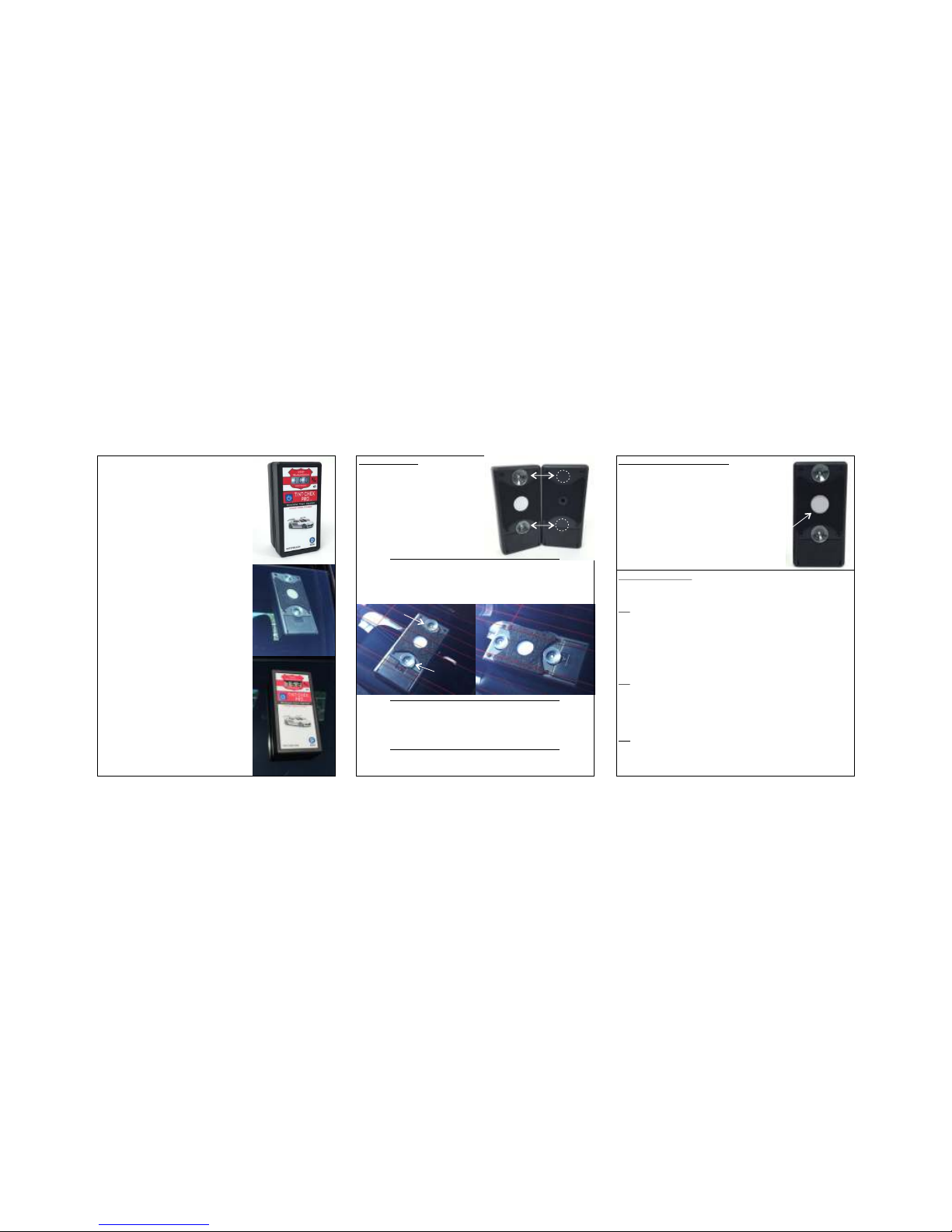
Clean the window area being tested.
Dirty glass can affect the accuracy of
your results.
Place both units of the instrument
together, back-to-back, with no glass
between them. Allow the magnets to
help align the two units, and then turn
the power on.
Wait for the instrument to register a
value of 100% on the display, and then
pull the two instrument halves apart.
Place the reflector unit on the inside of
the window being tested. Push the
reflector enclosure FIRMLY against the
window so the suction cups secure the
enclosure in place.
Place the instrument unit on the exterior
of the window being tested. Again allow
the magnets to help align the two
instrument halves.
Once the instrument unit is in position,
momentarily press and release the
power switch to view the Light
Transmission results (VLT value).
After registering the VLT value, remove
the instrument from the window and it
will automatically power off, clearing
your VLT value from the display after a
short delay. Repeat the process from
Step 1 if you would like to confirm the
ac c u ra c y o f y o u r p r ev i o us
measurement.
OPERATING TIPS
Make sure the two enclosures fit
together properly when you begin.
The edges of the suction cups should
not be bent or altered in any way. You
will notice the felt pads on the back
of the enclosures are contoured so they
do not touch the suction cups when
the two enclosure halves are placed
together properly.
When testing the rear window of automobiles, take notice of the defrost
lines that are printed on the interior of the window. Suctions cups will NOT
stick if they are positioned on the defrost lines. If you can not find a location
where both suction cups will miss the defrost lines, rotate the reflector unit
90 degrees to position both suction cups in between the lines.
When your instrument is not being used, please store it in the carrying case
that was included. This will protect the product and keep it from getting
damaged or dirty while being stored. As with any test equipment, we do not
recommend storing the instrument in your automobile overnight during
extreme temperature seasons.
If at any time during the operation of the instrument you want to power the
unit off, press AND HOLD the power switch and the unit will shut off.
OPERATING TIPS . . . Continued
The reflector area must be properly maintained
in order for the instrument to continue providing
accurate results. Use compressed air to blow off
any dust that may accumulate over time. If there
are smudges on the reflector that can not be
removed by air, use a micro-fiber cloth to wipe
the lens clean.
1.
2.
3.
4.
5.
6.
7.
KEEP THIS REFLECTOR
AREA CLEAN
TROUBLESHOOTING
Incorrect usage or the encounter of unexpected conditions while testing can
result in the following ERROR CODES:
E1: The measured VLT value is LESS THAN the allowed percentage. The
E1 error may occur if the instrument is not properly aligned with the reflector
at start-up or during the actual measurement. It can also occur if you take a
measurement without placing it on glass, or are holding the instrument away
from the glass surface or in free air. To fix this problem, turn the instrument
off and make sure it is properly aligned with the reflector, with no glass in
between the two enclosures. Now turn the instrument on and conduct a
new test.
E2: The measured VLT value is GREATER THAN the allowed percentage.
The E2 error may occur if the instrument is not properly aligned with the
reflector at start-up, or placed against a different surface other than the
reflector at start-up. To fix this problem, turn the instrument off and make
sure it is properly aligned with the reflector, with no glass in between the two
enclosure. Turn the instrument on and conduct a new test.
E3: The starting value that was obtained on the reflector unit to calibrate the
device at 100% was different than expected. Make sure you properly align
the two enclosures at start-up. Also make sure the lens of the reflector is
clean. Use compressed air to blow off dust, or a micro-fiber cloth to remove
smudges.
Quick-Start Directions
Steps 2 & 3Steps 5 & 6 Step 4
NO
YES
o
ROTATED 90
 Loading...