

SOLAR TRANSMISSION & POWER MEASUREMENTS
2 2
CHOICE OF (BTU/HR*FT ) OR (W/M )
AUTO-POWER-OFF FEATURE TO CONSERVE BATTERY
MEMBRANE STYLE POWER SWITCH
REAL-TIME READINGS CONTINUALLY UPDATED
DIGITAL TECHNOLOGY WITH EXCELLENT RESOLUTION
MICROPROCESSOR CONTROL
NO ADJUSTMENTS OR CALIBRATIONS NECESSARY
END-MOUNTED SENSOR
SMALL, PORTABLE CONVENIENT SIZE
The Digital "SOLAR TRANSMISSION & POWER METER" incorporates two meters into
one. In Power Mode, the meter measures the power per unit area of incident solar
radiation reaching the meter's sensing area. In Transmission Mode, the SP2065 is
able to calculate the solar transmission percentage associated with a given
material. The meter uses a state-of-the-art sensor coupled with microprocessor
control to achieve an EASY TO READ hand-held meter. The device may be used to
measure the solar characteristics of windows, film or other transparent materials.
GENERAL DESCRIPTION:
FEATURES:
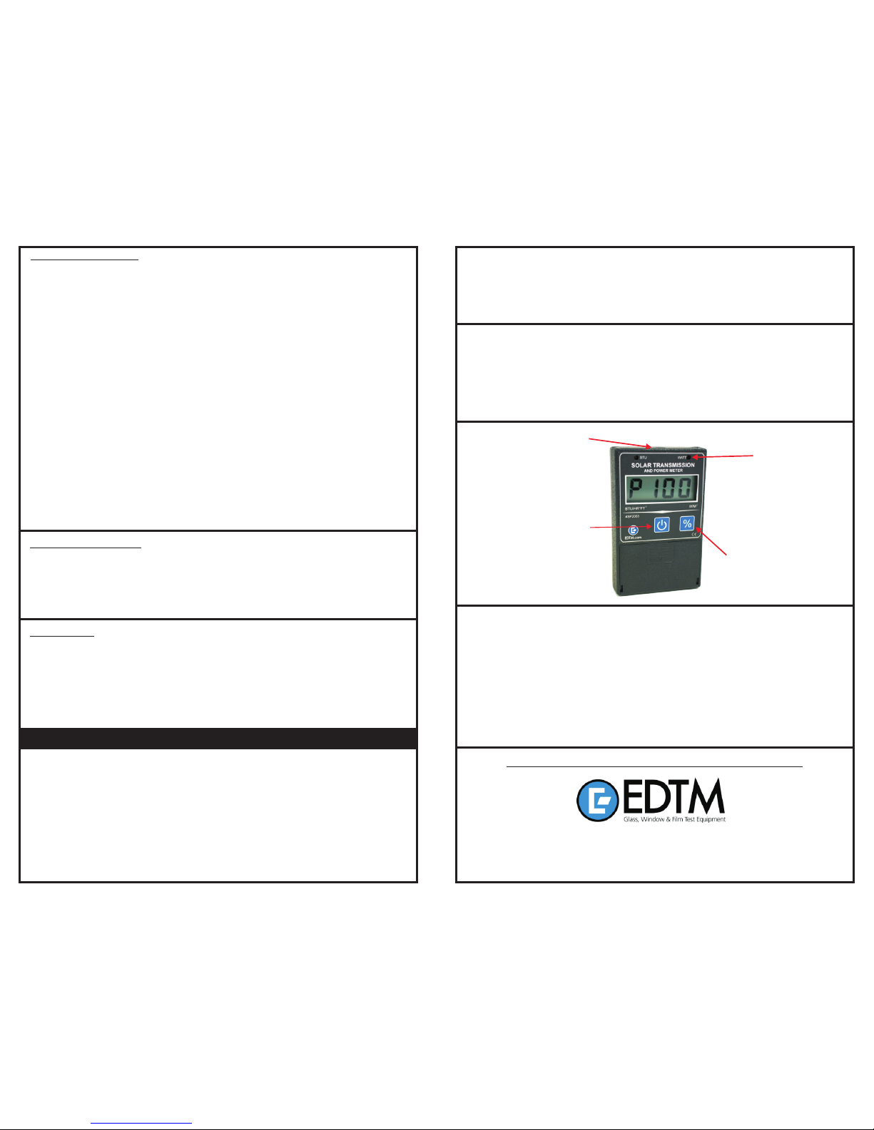
MODEL# SP2065 MADE IN THE USA
SOLAR TRANSMISSION
& POWER METER
LIGHT
SENSOR
sp2065_120829.cdr
SP2065 WARRANTY
The manufacturer warrants all models of the SP2065 to be free from defects in material and
workmanship under normal use and service as specified within the operator's manual. The
manufacturer shall repair or replace the unit within six (6) months from the original date of
shipment after the unit is returned to the manufacturers factory, prepaid by the user, and
the unit is disclosed to the manufacturers satisfaction, to be thus defective. This warranty
shall not apply to any unit that has been repaired or altered other than by the
manufacturer. The aforementioned provisions do not extend the original warranty period
of the unit which has been repaired or replaced by the manufacturer. Batteries are not
covered by warranty as well as damage caused by over-heating the device.
The manufacturer assumes no liability for the consequential damages of any kind through
the use or misuse of the SP2065 product by the purchaser or others. No other obligations or
liabilities are expressed or implied. All damage or liability claims will be limited to an amount
equal to the sale price of the SP2065.
POWER/TRANSMISSION %
SELECTOR SWITCH
POWER
BUTTON
BATTERY REPLACEMENT
CALIBRATION
The SP2065 is powered by a 9 volt battery. When the battery voltage is getting too
low to operate the meter, the display will begin blinking. Once the display begins
blinking you will want to replace the battery soon. To replace the batter y, turn off the
power meter. Remove the battery cover near the bottom of the meter and
replace with a new battery. Alkaline batteries will provide the longest service, but
are not required for this product.
This instrument has been calibrated to detect the total incident solar power of the sun.
The largest incident value of solar power is obtained when the end of the meter faces
the sun directly. When the end of the meter does not face the sun, the incident solar
power is reduced by the cosine curve of the angle to the sun. Make sure the
transparent materials being tested are reasonably clean.
This instrument is factory calibrated to a NIST (NATIONAL INSTITUTE OF STANDARDS AND
TECHNOLOGY) traceable thermopile and should require no field adjustment.
KEEP THE COMPETITIVE EDGE WITH PRODUCTS FROM
745 Capital Commons Drive
Toledo, Ohio 43615 USA
PHONE: (419) 861-1030 FAX: (419) 861-1031
WWW.EDTM.COM Email: sales@edtm.com
UNIT OF MEASURE
INDICATOR LEDS
1. If taking measurements near a heat lamp, do not place the meter too close to the
light source. If the end of the meter begins to feel hot to the touch, it is too close to the
light source. Extended periods of heat exposure can cause deformation of the filters,
resulting in a change in the accuracy of the meter. It is recommended that the heat
lamp and meter are separated by at least 18 inches (46 cm).
2. When taking measurements for transmission percentage or comparative tests, it is
important that the meter is held in the exact same position for both measurements
(when possible). Any change in angle or proximity to your light source can adversely
affect the accuracy of your measurements. FOR BEST RESULTS, place the meter on top
of a stand (#SP2075). It is best to leave the heat lamp and meter stationary, while
sliding the glass sample in between them. This will guarantee the most accurate
measurements possible.
3. When performing tests, it is advised to take multiple readings to reduce the amount of
error that occurs. Be aware that a changing light source (sun with moving clouds) will
affect your measurements.
4. The light sensor is located at the top end of the enclosure. For the greatest accuracy
in measurements, this sensor should be directly facing the light source. DO NOT alter the
condition of the sensor opening by touching or pushing on the filter. Any modifications
or altering of the exterior surface of the white filter WILL affect the calibration of the meter.
This area should be kept clean at all times. Compressed air or a lint-free cloth should be
used to clean the filter surface if it becomes soiled.
5. Do not attempt to open the enclosure. Opening the enclosure will void the product
warranty and affect the calibration of the SP2065 meter.
HELPFUL OPERATING TIPS
The SP2065 is designed to operate in either power mode or transmission mode. While
operating in power mode, the SP2065 is identical to our SP1065 meter. However, when the
SP2065 is switched into transmission mode, the meter self-calibrates to read 100%
transmission for the current solar conditions presented to the meter. Thereafter all readings are
referenced against the solar conditions that were present when the self-calibration occurred.
Therefore if you place a piece of glass that passes 40% of the solar energy between the meter
and the light source, the display will read P 40 (i.e. 40 % solar transmission).
The SP2065 is helpful in demonstrating the performance of fenestration products. Even more
importantly, the SP2065 can be used to identify types of Low E coatings in the field. By knowing
the general performance of specific coatings, the user can differentiate types of coatings
MEASURING INSTALLED WINDOWS
The best results are obtained when the meter is operated on windows that are directly
facing the sun. The position of the meter is EXTREMELY important in obtaining an
accurate reading. The meter should be placed on the window sill on top of it's stand or
other stationary item that will hold the meter in the same position. To take a transmission
reading, the meter should be self-calibrated with the window open (Step 3 & 4 above).
The sensing area of the meter should NOT be looking through any glass or film at this
time. In step #5 of the instructions, you should close the window without moving the
position of the meter. Once the window is closed, the meter will measure the solar
energy that is transmitting through the window. Several readings should be taken to
guarantee the most accurate information is obtained. Please note that outdoor
conditions are ever-changing. Clouds and environmental conditions can change
the incident solar energy quickly.
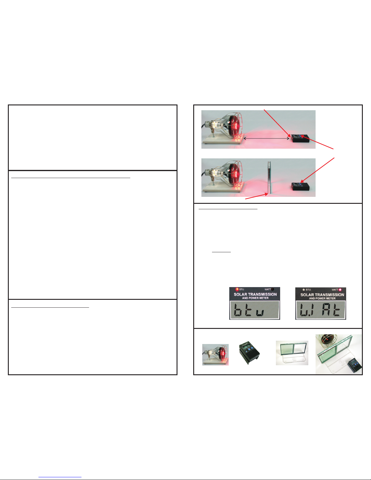
SAMPLE BEING TESTED
STEPS 2 - 4
STEP 5 & 6
% TOGGLE
BUTTON
TABLETOP DEMONSTRATIONS/QC WORKSTATIONS
To set up a TABLETOP DEMONSTRATION, or to perform readings in a bench-type QC
application, place a light source facing the SP2065. The light source should be
stable and locked in position so it cannot move during the measurements. Position
the meter flat on the table with the sensor facing the light source directly. If
necessary, place the SP2065 on top of a stand (#SP2075) to position the meter in the
center of the light beam. To obtain the most accurate results, DO NOT move the light
source OR the meter during the readings. To take solar transmission measurements,
follow the steps below and the illustrations on the next page:
1) Turn on the SP2065 by pushing the power button
2) Place the meter on the table or platform with the light sensor (top end of
meter) facing the light source directly. Turn on the light source and confirm
that a power reading has registered on the display.
3) Self-calibrate the meter by pressing the BLUE % switch next to the power button.
4) The display should now read P100 (=100% transmission). Your meter is now
prepared to take a transmission measurement with the current light
conditions. (If the surrounding light conditions change, repeat STEP 3).
5) Place the window or film sample between the light source and the SP2065.
6) The resulting solar transmission percentage for that material will be displayed.
7) Remove the sample and confirm the SP2065 returns to P100. If the meter
does not display P100 with the sample removed, disregard the reading and
begin the test process again.
INFRARED HEAT LAMP
EDTM MODEL# HL1040
LIGHT SENSOR
sp2065_120829.cdr
FIGURE 1
MINIMUM 18”
ACCESSORIES
For more information and a complete list visit EDTM.com.
#HL1040
Heat Lamp
#SP2075
Stand
#HS2056
Demonstration Base
CHANGING THE UNIT OF MEASURE
2 2
The SP2065 accommodates measurements in units of both Watts/Meter and BTU/hour*foot .
At start up, the meter will indicate the current setting on the LCD display (See Figure 1), as well
as by indicating the unit of measure by the LED indicators. The meter will retain the previously
established unit of measure until it is modified by the user. Therefore you do not have to
modify it each time the meter is powered on. Follow the instructions below to change the unit
of measure.
1) Power the unit on and release the power button.
2) Press AND HOLD the power button as though you are turning it off.
3) The display will go blank as though the instrument is turning off.
4) Continue to hold down the power button for 3 seconds.
5) The display will briefly show the current setting, and then switch to the new setting.
6) The LED indicator will also switch to the new setting to confirm your choice.
7) When the screen shuts off again release the power button.
8) The next time you turn the meter on, it will function in the new unit of measure.
2
Indicates BTU/hr*ft
2
Indicates W/m
 Loading...