

Page 1
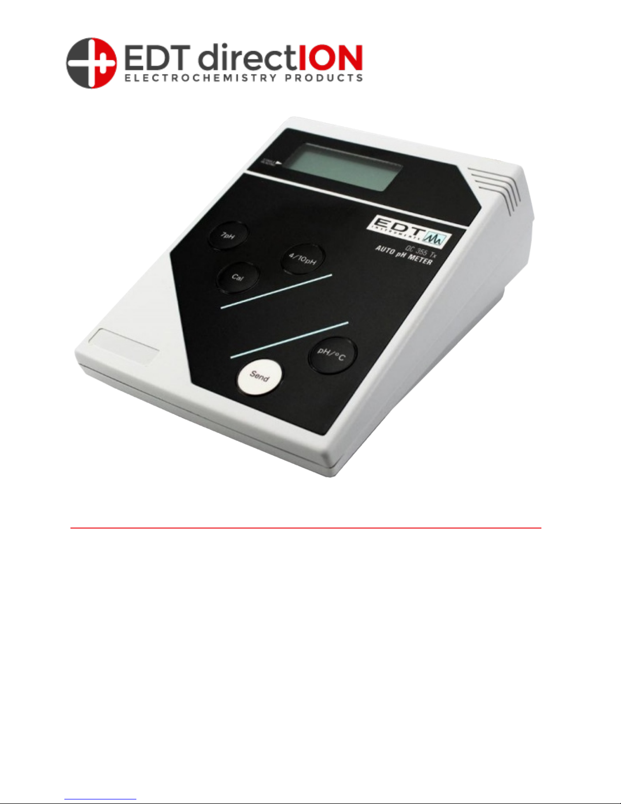
Table of Contents
Section 1 - Introduction and Set Up
Section 2 - pH Calibration & Measurement
Section 3 - Use with a Printer or Computer
Section 4 -
Section 5 -
Appendix 1 - pH Electrodes
Troubleshooting
Specification
QC355TX - Routine QC pH Meter - Users Manual
Page 2
SECTION 1 - Introduction
Description
The QC355(Tx) pH meter is a simple-to-operate bench pH meter. The meter
utilises automatic calibration to one or two points: automatic temperature
compensation is compulsory and the inbuilt calibration clock reminds the user
when re-calibration is necessary.
Unpacking
Verify that you have received all equipment. If you have any questions about the
shipment, please call EDT Direct ION Ltd. or your agent.
When you receive the shipment, inspect the container for any signs of damage.
Note any evidence of rough handling in transit. Immediately report any damage to
the agent.
Note
The carrier will not honour any claims unless all shipping material is saved for
their examination. After examining and removing contents, save packing material
in the event that re-shipment be necessary.
The following items are packed in the box:
QC355TX Meter E8051 Temperature Probe E8061 Electrode Stand
AC Adapter 9V Battery pH Buffers 4,7,10 Operator’s Manual
Setting Up - AC Operation
Only use the approved power adaptor supplied
Check that the adaptor is the correct voltage for your power supply
Plug the adaptor into the power socket at the back of the meter, then connect to
the AC supply.
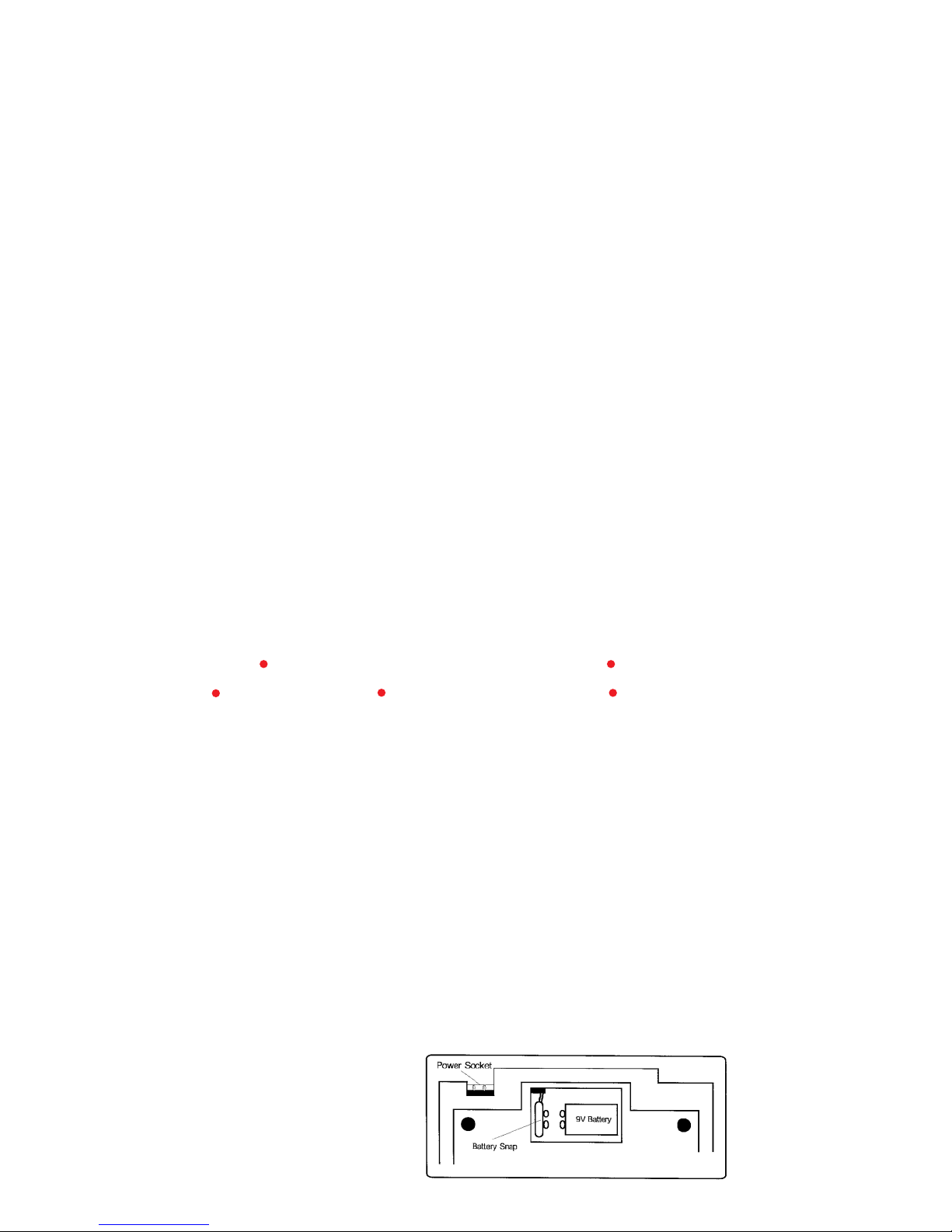
Battery Installation
Approximately 24 hours of continuous use is afforded by the 9V battery.
The BAT flag appears on the display to indicate a low battery.
To install or replace the battery, slide off the back cover
Remove the old battery and insert a new one ensuring that the polarity is correct
Replace back cover.
Figure 1. Bottom view of instrument
showing power connections
Page 3
Setting Up (Continued)
A Note on Electrodes
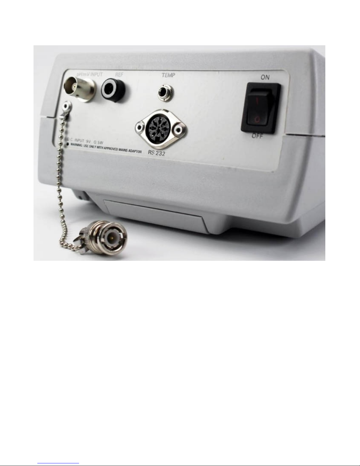
pH, Ion Selective and Redox electrodes may all be used with the QC355. These
may be combination or half-cell types. Combination or sensing half-cells should
have a BNC terminal and be connected to the socket marked pH/ION input at the
back of the meter. Reference half-cells should have a 4mm bunched terminal
and be connected to the socket marked REF. Always refer to electrode
instructions before use. See also, Appendix 1.
Figure 2. Rear view of QC355(Tx)
Page 4
Section 2 - pH Calibration and Measurement
For accurate results, stir all buffers and samples. Always rinse electrodes and blot dry
before transferring from one solution to another to prevent contamination. Ensure that any
electrode filling holes are left uncovered during use.
Automatic Calibration & Temperature Compensation
1. Connect the pH electrode(s) and temperature probe and switch on using the power
ON/OFF switch on the back panel.
2. Select pH mode by pressing the pH/°C key. Note: A flashing display indicates that the
instrument is uncalibrated.
3. Place the pH electrode(s) and the temperature probe in the pH 7 buffer and wait for a
stable reading. Indicated by ◄ on the display.
4. Press the CAL key– CAL flag will flash. Press the 7pH key—CAL flag will stop flashing. The
first calibration point has now been entered automatically at the correct value for the
temperature of measurement.
5. Rinse, blot and place electrode(s) and temperature probe in pH buffer 4 or 10. Wait for a
stable reading indicated by ◄on the display.
6. Press the CAL key– CAL flag will flash. Press the 4/10pH key—CAL flag will stop flashing.
The second calibration point has now been entered automatically at the correct
value for the temperature of measurement.
7. pH measurements may now be made by immersing rinsed electrodes in the sample and
recording the stable reading indicated by the ◄ flag.
8. To read the temperature press the pH/°C key at any time.
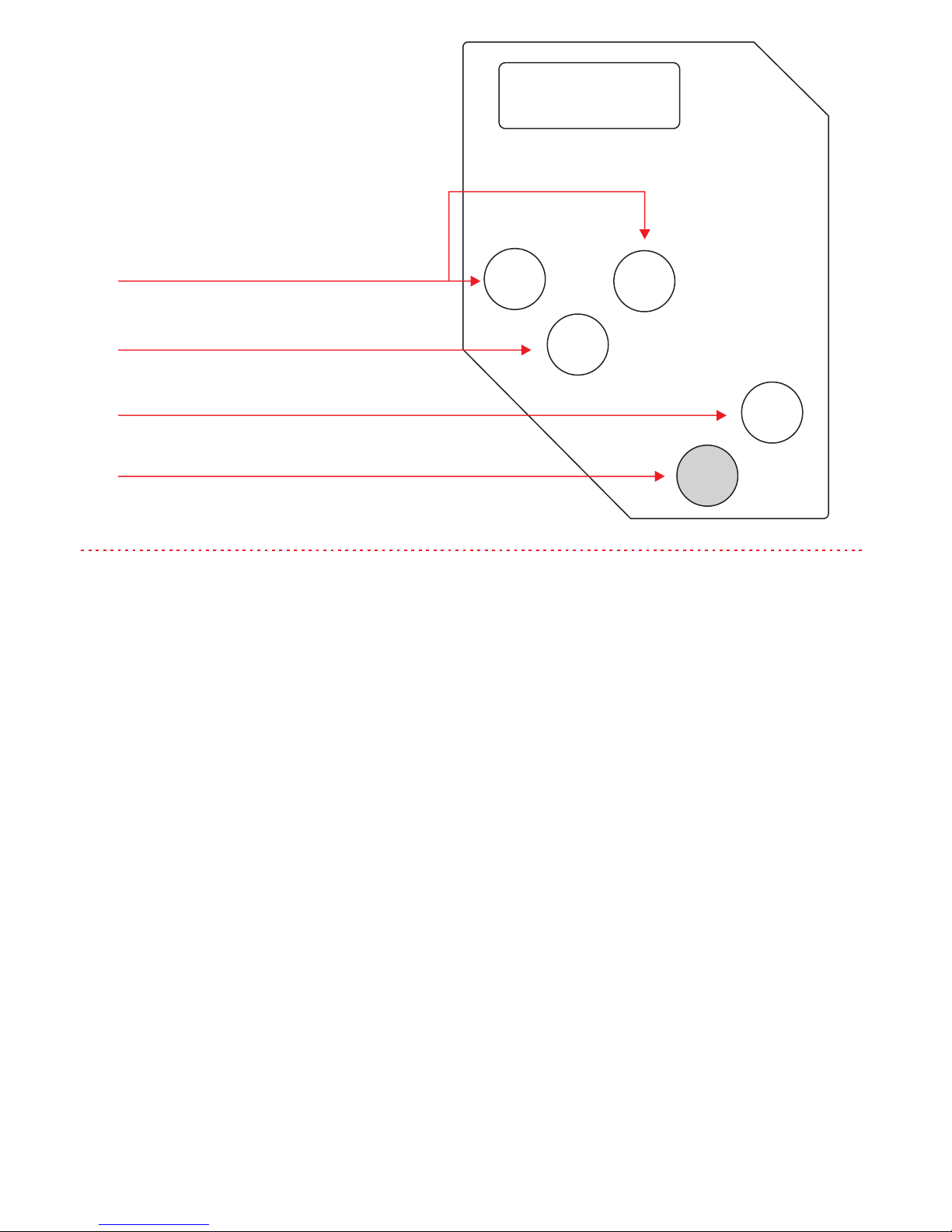
7pH
4/10pH
Cal
Send
pH/°C
Calibration Keys, automatically
selects and enters correct pH value
Starts calibration routine
Selects pH or temperature mode
Transmits data to printer or computer
Figure 3. Front Panel
Page 5
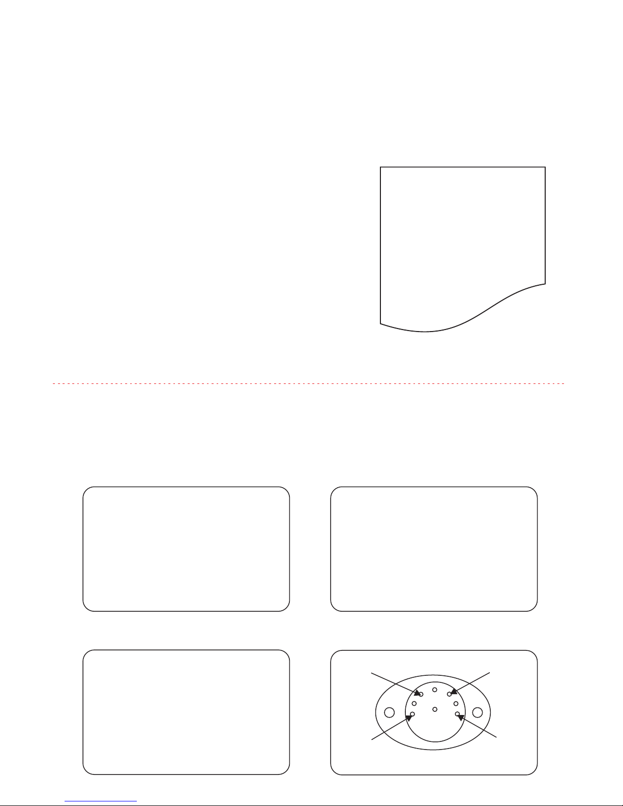
Section 3 - (Tx Version Only) Operation With a Printer or Computer
Printer
1. Connect a printer (set at 1200 Baud) to the meter via the RS232C port on the back panel.
2. Follow the calibration procedure given in Section 2
3. To print out a sample reading, press the Send key. The first time the key is pressed the
following printout is obtained
Computer
Connect a computer using 1200 Baud via the RS232C port at the back of the meter. A
computer program is required to receive and send characters from the computer. The
current readings can be sent to the computer by pressing the Send key. Each line is
terminated with a Carriage Return (CR), Line Feed (LF). All characters are ASCII printable
alpha-numeric
Three commands, CA, PR and RD can be sent from the computer:
DATE………………….
OPERATOR…………...
SAMPLE………………
pH = 7.00pH T=21.7°C
Command—CA
1 CR LF
pH = 7.06 CR LF
T = 15.8 °C CR LF
mV = -0.2mV CR LF
2 CR LF
Second calibration point
Command—RD
pH = 7.00pH CR LF
T = 21.5°C CR LF
mV = 0.2mV CR LF
CA—Send Calibration Data
RD –Send Current Readings
Command—PR
Sl = 95.3% NERNST CRLF
E° = 5.2mV CR LF
PR –Send Probe Status Data
RS232 Connection details
Rx
Tx
CTS
GND
4. Pressing and releasing the Send key subsequently
will result in a printout of the displayed reading and
temperature only.
5. To obtain a printout of other parameters for the
same sample, press the Mode key and then the
Send key
6. To print a new identifier, press and hold down the
Send key.
Page 6

Section 4 - Troubleshooting
Symptom
Probable Cause
No display
Battery is flat or not installed
Power supply disconnected
‘BAT’ flag displayed
Battery Low
Wildly erratic readings or display reads -on left hand side
Electrodes disconnected
Electrodes not immersed in solution
Reference electrode not filled
Reference junction dry
Drifting readings
Inconsistent or lack of stirring
Reference filling solution contaminated
Buffers contaminated
Erratic/drifting readings or display reads –
on left hand side when shorting plug is
attached.
Return meter for servicing
Error Codes
PRO Temperature probe malfunctioning or not connected
Buf Wrong or Contaminated Buffer
SL Poor Electrode Slope caused by faulty electrode or poor
buffers/ standards
E° Faulty or Aged electrode
E6, E7 Calibration error. Recalibrate with fresh standards or buffers
Electrodes out of solution.
In the event of a malfunction, it is important to pinpoint the problem to either the meter
or the cell. If a spare cell is available, substitute it for the one in use.
There are no user serviceable parts in this instrument. Please ensure that the instrument,
together with all accessories, is returned to EDT Direct ION Ltd or the agent with a full
description of the symptoms.
No attempt should be made to repair the meter.
Page 7

Section 5 -
Appendix 1
Specifications
pH electrodes
Before Use
Remove the protective cap covering the glass sensing bulb and replace with the
protective guard if applicable. Inspect the filling solution for air bubbles and remove
by shaking in a downward direction. Soak the electrode in pH storage solution for 30
minutes.
Cleaning
Soak the electrode in 0.1M HCl for 15 minutes followed by soaking in pH storage
solution for 30 minutes
Storage.
Put some pH storage solution in the protective cap and place over the glass bulb.
Never store the electrode in distilled or de-ionised water. Never allow the electrode to
dry out.
pH electrode storage solution is made up by dissolving 1g KCl in 100mL of pH 7 buffer
pH Range 0.00 to 14.00
pH Accuracy ±0.02pH
Temperature Compensation 0-100°C
Auto Calibration 2 points, 7 or 4/10
°C Range
-30.0 to +130.0°C
°C Resolution
0.1°C
°C Accuracy
±0.3°C
Display
Power
Instrument Size
Instrument Weight
12.7mm LCD
9V Battery or AC
210 x 150 x 88mm
550g
Page 8

For more information on our products
please visit our website www.edt.co.uk
EDT directION
Unit 5 Waldershare Park, Dover. CT15 5DQ.
Telephone: 01304 829960 Email: [email protected]
Company No, 04135318 VAT No. GB 765175410
 Loading...