

Page 1
User’s Guide
VisionLink RCX
Remote Camera Link extender
for use with Camera Link cameras
Date: 2016 August 30
Rev.: 0002
Page 2

EDT | Engineering Design Team, Inc.
3423 NE John Olsen Ave.
Hillsboro, OR 97124
U.S.A.
Tel: +1-503-690-1234 | Toll free (in U.S.A.): 800-435-4320
Fax: +1-503-690-1243
www.edt.com
EDT
TM
and Engineering Design Team are trademarks of Engineering Design Team, Inc. All other trademarks, service marks,
TM
and copyrights are the property of their respective owners†.
© 1997-2019 Engineering Design Team, Inc. All rights reserved.
EDT, Inc. 2
Page 3

Terms of Use Agreement
Definitions. This agreement, between Engineering Design Team, Inc. (“Seller”) and the user or distributor (“Buyer”), covers the
use and distribution of the following items provided by Seller: a) the binary and all provided source code fo r any and all device
drivers, software libraries, utilities, and example applications (collectively, “Software”); b) the binary and all provided source code
for any and all configurable or programmable devices (collectively, “Firmware”); and c) the computer boards and all other physical
components (collectively, “Hardware”). Software, Firmware, and Hardware are collectively referred to as “Products.” This
agreement also covers Seller’s published Limited Warranty (“Warranty”) and all other published manuals and product information
in physical, electronic, or any other form (“Documentation”).
License. Seller grants Buyer the right to use or distribute Seller’s Software and Firmware Products solely to enable Seller’s
Hardware Products. Seller’s Software and Firmware must be used on the same computer as Seller’s Hardware. Seller’s Products
and Documentation are furnished under, and may be used only in accordance with, the terms of this agreement. By using or
distributing Seller’s Products and Documentation, Buyer agrees to the terms of this agreement, as well as any additional
agreements (such as a nondisclosure agreement) between Buyer and Seller.
Export Restrictions. Buyer will not permit Seller’s Software, Firmware, or Hardware to be sent to, or used in, any other country
except in compliance with applicable U.S. laws and regulations. For clarification or advice on such laws and regulations, Buyer
should contact: U.S. Department of Commerce, Export Division, Washington, D.C., 20230, U.S.A.
Limitation of Rights. Seller grants Buyer a royalty-free right to modify, reproduce, and distribute executable files using the
Seller’s Software and Firmware, provided that: a) the source code and executable files will be used only with Seller’s Hardware;
b) Buyer agrees to indemnify, hold harmless, and defend Seller from and against any claims or lawsuits, including attorneys’ fees,
that arise or result from the use or distribution of Buyer’s products containing Seller’s Products. Seller’s Hardware may not be
copied or recreated in any form or by any means without Seller’s express written consent.
No Liability for Consequential Damages. In no event will Seller, its directors, officers, employees, or agents be liable to Buyer
for any consequential, incidental, or indirect damages (including damages for business interruptions, loss of business profits or
information, and the like) arising out of the use or inability to use the Products, even if Seller has been advised of the possibility
of such damages. Because some jurisdictions do not allow the exclusion or limitation of liability for consequential or incidental
damages, the above limitations may not apply to Buyer. Seller’s liability to Buyer for actual damages for any cause whatsoever,
and regardless of the form of the action (whether in contract, product liability, tort including negligence, or otherwise) will be
limited to fifty U.S. dollars ($50.00).
Limited Hardware Warranty. Seller warrants that the Hardware it manufactures and sells shall be free of defects in materials
and workmanship for a period of 12 months from date of shipment to initial Buyer. This warranty does not apply to any product
that is misused, abused, repaired, or otherwise modified by Buyer or others. Seller’s sole obligation for breach of this warranty
shall be to repair or replace (F.O.B. Seller’s plant, Beaverton, Oregon, USA) any goods that are found to be non-conforming or
defective as specified by Buyer within 30 days of discovery of any defect. Buyer shall bear all installation and transportation
expenses, and all other incidental expenses and damages.
Limitation of Liability.
whether such damages arise from, or are a result of, breach of contract, warranty, tort (including negligence), strict liability, or
otherwise. All references to damages herein shall include, but not be limited to: loss of profit or revenue; loss of use of the goods
or associated equipment; costs of substitute goods, equipment, or facilities; downtime costs; or claims for damages. Seller shall
not be liable for any loss, claim, expense, or damage caused by, contributed to, or arising out of the acts or omissions of Buyer,
whether negligent or otherwise.
No Other Warranties. Seller makes no other warranties, express or implied, including without limitation the implied warranties
of merchantability and fitness for a particular purpose, regard ing Seller’s Products or Documentation. Seller does not warrant,
guarantee, or make any representations regarding the use or the results of the use of the Products or Documentation or their
correctness, accuracy, reliability, currentness, or otherwise. All risk related to the results and performance of the Products and
Documentation is assumed by Buyer. The exclusion of implied warranties is not permitted by some jurisdictions. The above
exclusion may not apply to Buyer.
Disclaimer. Seller’s Products and Documentation, including this document, are subject to change without notice. Documentation
does not represent a commitment from Seller.
In no event shall Seller be liable for any type of special consequential, incidental, or penal damages,
EDT, Inc. 3
Page 4

Contents
Overview........................................................................................................................................................................................5
Care and Cautions ...............................................................................................................................................................5
Related Products..................................................................................................................................................................5
Related Resources...............................................................................................................................................................6
Setup .............................................................................................................................................................................................7
Adapter Cabling, Mounting, Safetying...........................................................................................................................................9
Status, Configuration, Operating Mode........................................................................................................................................10
Status.................................................................................................................................................................................10
Configuration......................................................................................................................................................................10
Operating Mode Details .....................................................................................................................................................11
Resetting or Changing the Operating Mode.......................................................................................................................11
Firmware......................................................................................................................................................................................12
Transceivers................................................................................................................................................................................12
Pin Assignments..........................................................................................................................................................................13
Camera Link.......................................................................................................................................................................13
Power Connector ...............................................................................................................................................................13
Cable assembly – Lemo to loose wire......................................................................................................................14
Cable assembly – Lemo to male DB9 ......................................................................................................................14
Cable assembly – Lemo to female DB9 RS232.......................................................................................................14
Power Supply...............................................................................................................................................................................15
Dimensions..................................................................................................................................................................................16
Revision Log................................................................................................................................................................................17
EDT, Inc. 4
Page 5
VisionLink RCX Remote Camera Extender
Overview
The VisionLink RCX is a base-mode extender which adapts Camera Link over fiber, providing electrical isolation and
extended range. It supports most base-mode cameras from 20 to 85 MHz, at serial data rates of up to 19.2 Kb/s.
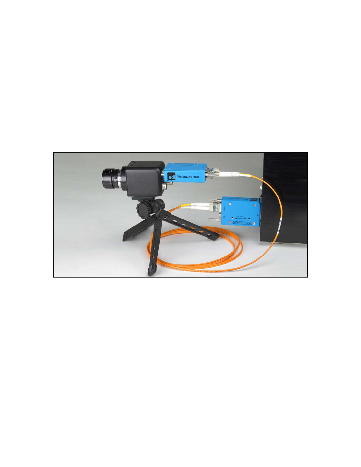
A pair of VisionLink RCX extenders, with fiberoptic cable, replaces standard Camera Link cable as shown in Figure 1.
Figure 1. Two VisionLink RCX extenders with fiber
Care and Cautions
When opening and handling EDT products, always follow electrostatic dissipative procedures (see edt.com/static).
Your EDT extender, though built to withstand a wide range of conditions as listed in its datasheet specifications, is still
a high-performance component which must be treated with care for optimal results.
In particular, the connectors – especially the fiberoptic transceivers – must be kept clean and dry. If you suspect the
presence of moisture or debris in the connectors, you should blast a burst of compressed air...
• directly into the ports to dislodge any debris there; and
• away from the electronic components to blow out any moisture in the air nozzle.
CAUTION To avoid damaging your eyesight, never look directly into any fiberoptic transceiver.
Related Products
The base-mode VisionLink RCX is compatible with the earlier RCX C-Link extender. For other modes, use a set of RCX
C-Link medium- or full-mode extenders. To find details on these extenders and other EDT vision products (for example,
framegrabbers), see Related Resources.
EDT, Inc. 5
Page 6

VisionLink RCX Overview
Related Resources
The resources below may be helpful or necessary for your applications.
NOTE For complete resources and documentation on any EDT product – visit edt.com and navigate to the product page,
or go to the download hub (edt.com/download-hub) and look under the product name.
EDT Resources
• Installation instructions edt.com/download-hub
• VisionLink RCX datasheet / specifications “
• VisionLink RCX quick start guide “
• Block diagrams “
• Videos and tutorials “
• RCX C-Link user’s guide and datasheet / specifications edt.com/product/rcx-c-link
Third-Party Resources
• PCI Express (PCIe) specifications www.pcisig.com
• Camera Link specifications www.visiononline.org
• Timecode (IRIG-B) specifications irigb.com
EDT, Inc. 2016 August 30 6
Page 7

VisionLink RCX Setup
VisionLink RCX
LC duplex
fiberoptic
transceiver:
- transmit
- receive
Power (Lemo
or Switchcraft)
Hirose (future use)
LED
thumbscrews
MDR26
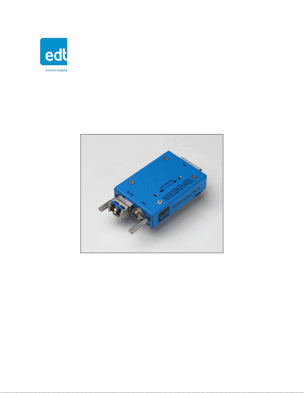
Setup
Each extender unit is preset and prelabeled to connect to either a camera or a framegrabber (Figure 2). Each unit, in
order to work properly, must be connected to the type of device for which it is set.
NOTE If you reconfigure an extender, relabel it immediately to avoid confusion later.
Figure 2. Fiberoptic extender, labeled with factory presets
The label at the far right shows the unit’s factory presets, including:
• the device (camera or framegrabber) for which the unit is preset;
• the operating mode (blink code) for which the unit is preset (see
Configuration on page 10).
After you have checked the labeling, you can connect each extender as explained below.
• Device end: Attach the correct device (camera or framegrabber) to the extender’s MDR26 connector.
• Cable end: Attach the correct cabling to the extender’s cable connectors.
Figure 3 shows the extender connectors and other features, including the LED (explained in Status, Configuration,
Operating Mode on page 10).
Figure 3. VisionLink RCX – connectors and features
a. Cable end – connectors b. Cable end – other features
c. Device end – connector
d. Extender connected to camera
EDT, Inc. 2016 August 30 7
Page 8
VisionLink RCX Setup
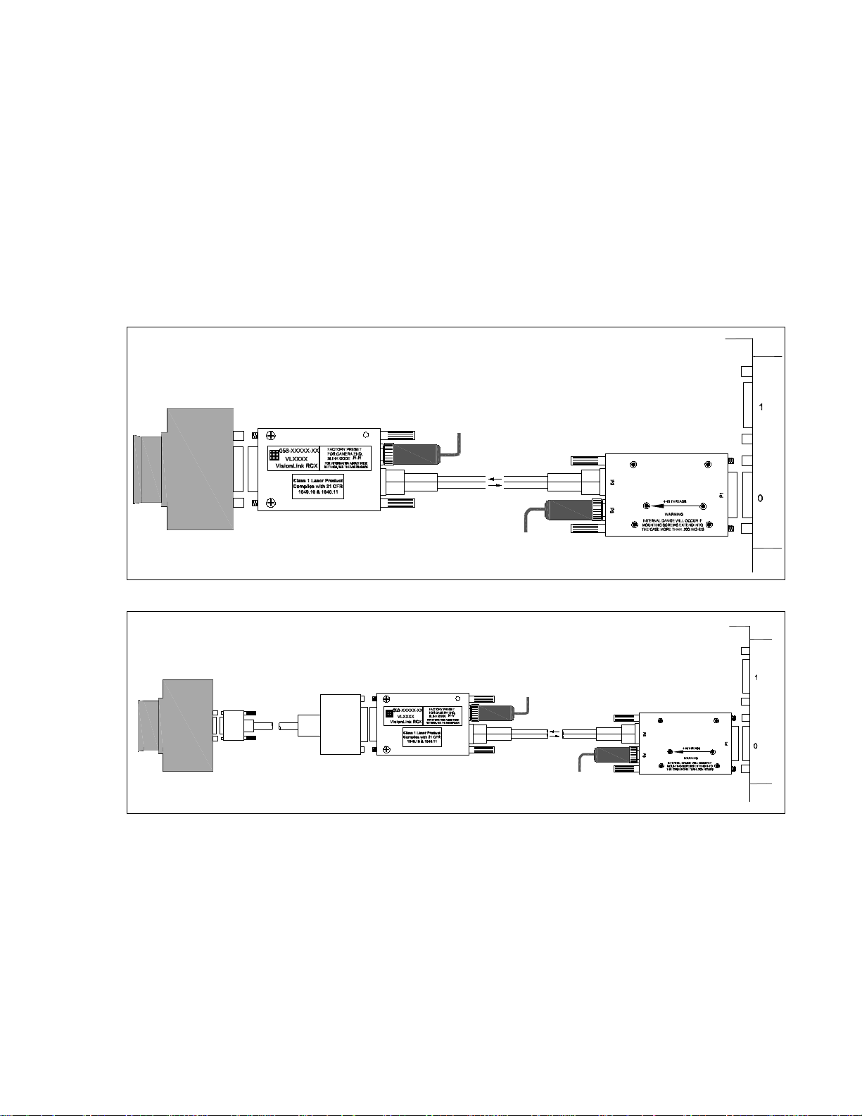
Base mode requires two extenders: one at the camera end, and the other at the framegrabber end.
To set up this system...
1. Install the framegrabber according to its user’s guide (for EDT user’s guides, see edt.com/download-hub).
2. Verify the extenders are configured properly (see Configuration on page 10) – one for the camera end, and one for
the framegrabber end.
3. Turn off power to all devices.
4. Connect the extender labeled “Camera End” to the MDR26 connector on the camera and the extender labeled
“Framegrabber End” to the MDR26 connector on the framegrabber, as shown in Figure 4 below.
NOTE An adapter may be required in some setups, such as those with devices using SDR connectors; for details, see
Figure 5 below and Adapter Cabling, Mounting, Safetying on page 9.
Figure 4. Base mode setup with devices using MDR26 connectors
Figure 5. Base mode setup with MDR26-SDR26 adapter at camera end
5. Connect the two extenders’ transceivers to each other with fiberoptic cabling (see Transceivers on page 12).
6. Connect each extender’s power connector to the power supply (see Power Supply on page 15).
7. Turn on power to all devices.
8. Verify each LED shows a steady light (for LED details, see Status, Configuration, Operating Mode on pag e 10).
EDT, Inc. 2016 August 30 8
Page 9

VisionLink RCX Adapter Cabling, Mounting, Safetying
Mounting holes
Safety wire
running through
hole,
notch, no
and bale strap
Adapter Cabling, Mounting, Safetying
You may need adapter cabling, either from EDT or from a third party, in some cases – for example...
• To connect the extender in applications with limited space or other constraints.
• To connect the extender to an EDT VisionLink framegrabber or any other device using an SDR connector.
Table 1 shows the adapter cabling available from EDT and how to attach it to the extender.
Table 1. Using adapter cabling from EDT
Part # Description Attachment instructions
016-13740 MDR26 female to SDR26 male, 2.0M Secure the
016-13779 MDR26 female to SDR26 male, 1.0M
016-14199 MDR26 female to SDR26 male, 0.5M
016-02563 MDR26 female to MDR26 male, 0.5M
extender to
the adapter
cable via the
extender’s
thumbscrews.
In most cases, mounting the extender to the device via the thumbscrews is sufficient. However, some settings – e.g., a
high vibration environment on an aircraft – may require additional methods to secure the extender and fiberoptic cable.
In such settings you can mount the extender by using the two 4-40 thread mounting holes with a custom (user-provided)
bracket – for the precise locations of these holes, see Dimensions on page 16. Also, you can secure the fiberoptic
transceiver’s bale strap with safety wire. For details on mounting holes and safety wire, see Figure 6.
Figure 6. Using the mounting holes and safety wire
a. Mounting holes b. Safety wire
To use the 4-40 thread mounting holes:
Add your own custom bracket, designed to match the exact
location of the holes (see Dimensions on page 16).
CAUTION – To avoid damage to the extender, the mounting
screws cannot extend more than 0.2" into the case.
To use safety wire:
Thread the safety wire through the bale strap and the hole and
notch in the backshell. EDT recommends using .022 gauge
aviation safety wire and other supplies from an aviation
supplier – for example, www.aircraftspruce.com (Aircraft
Spruce and Specialty). For aviation applications, follow
relevant Federal Aviation Administration (FAA) guidelines and
best practices for safetying items on aircraft; see FAA
Advisory Circular (AC) 43.13-1B at www.faa.gov.
EDT, Inc. 2016 August 30 9
Page 10

VisionLink RCX Status, Configuration, Operating Mode
Status, Configuration, Operating Mode
Each extender has a light-emitting diode (LED), as in Figure 3b. By displaying various patterns of blinks, the LED
communicates information about the extender’s configuration and status, as follows.
• At power-on, the LED blinks a one-time configuration code to indicate the operating mode for which the extender
is configured, and then blinks rapidly as the firmware loads.
• After power-on, the LED continuously displays a status code which shows steady green if the unit is working properly, or shows a different blink pattern if there is an error.
This section explains the status and configuration codes, as well as the related operating modes.
Status
As stated above, at power-on the LED will blink the extender’s configuration code on e time, Then it will blink quickly
while the firmware loads. After power-on, the LED continuously displays the extender’s status code, which indica tes
whether the unit is working properly or has errors (see Table 2).
Table 2. Status codes
LED behavior Significance
Steady light All OK – everything is working properly.
Slow blinks (1Hz) There is an error from the other end. The typical causes are:
• The extender at the other end has no power, or its operating mode does not match the operating mode on
this extender (see Configuration on page 10).
• The cable connection is compromised, either by incorrect or damaged cabling, or by moisture or debris in the
extender’s cable connectors (see Care and Cautions on page 5).
Fast blinks (10Hz) There is an error from the camera to the extender, related to the camera’s pixel clock.
Both slow and fast
blinks
2 fast + 2 slow + 2
fast blinks
No light The extender has no power or is faulty.
Configuration
Each extender is preset and prelabeled for the operating mode you specified in your product order. The operating mode
is selected and indicated through a blink pattern, displayed once at power-on, called the LED configuration (blink) code.
The LED configuration code consists of two digits, each represented by a certain number of blinks. The two digits are
separated by a pause, shown in this guide as a hyphen. For example, a configuration code of “one blink, pause, one
blink” is shown in this guide as 1-1.
A first digit of 1 means the unit is configured for the camera end; a first digit of 2 indicates that the unit is configured for
the framegrabber end. The second digit must be the same for both ends (camera and framegrabber). With an EDT FOX
framegrabber, there is no extender at the framegrabber end, so the configuration code is set at the camera end only.
For a typical base-mode system, a configuration code of 1-1 at the camera end and 2-1 at the framegrabber end permits
standard base-mode operation at clock frequencies of 20–40 MHz.
If the fast blink is on the camera-end extender: either the camera has no power, or the operating mode on the
extender does not match the operating mode on the camera (see Configuration on page 10).
If the fast blink is on the framegrabber-end extender: either the extender or the resync cable is faulty.
There is at least one slow-blink error and at least one fast-blink error.
The extender is configured with an unsupported operating mode (see Configuration on page 10).
EDT, Inc. 2016 August 30 10
Page 11

VisionLink RCX Status, Configuration, Operating Mode
Table 3 shows the configuration blink codes for standard usage and RCX C-Link emulation.
Table 3. Configuration codes
Standard usage RCX C-Link emulation
Unit
connects
to
camera 1-1 20–40 MHz 24 1.250 Gb/s 3-1-1 20–40 MHz 24 1.250 Gb/s
camera 1-2 20–80 MHz 24 2.500 Gb/s 3-1-2 20–60 MHz 16 1.250 Gb/s
camera 1-3 20–85 MHz 24 3.125 Gb/s 3-1-3 20–60 MHz 24 2.500 Gb/s
camera 1-4 20–80 MHz 24 2.500 Gb/s 3-1-4 60–80 MHz 24 2.500 Gb/s
framegrabber 2-1 40 MHz 24 1.250 Gb/s 3-2-1 40 MHz 24 1.250 Gb/s
framegrabber 2-2 80 MHz 24 2.500 Gb/s 3-2-2 60 MHz 16 1.250 Gb/s
framegrabber 2-3 85 MHz 24 3.125 Gb/s 3-2-3 60 MHz 24 2.500 Gb/s
framegrabber 2-4 80 MHz 24 2.500 Gb/s 3-2-4 80 MHz 24 2.500 Gb/s
Blink
code
(N-N)
Pixel
clock
rate
Bits
per
clock
Link rate
between
units
Blink
code
(3-N-N)
Pixel
clock
rate
Bits
per
clock
Link rate
between
units
Operating Mode Details
In base mode, each pixel clock transfers up to 24 bits of video data from the camera’s X channel. The extender can
transfer four camera control signals and has a bidirectional serial interface between framegrabber and camera. The
extender generates its own pixel clock, so the clock rate into the framegrabber may exceed the rate of the camera. Thus,
the amount of time spent in blanking will vary from line to line and frame to frame.
At reset (and whenever the extender cannot lock to the camera clock), the extender initializes to assume that the
Camera Link data-valid signal is never asserted, and ignores it. Many Pulnix cameras do not assert data-valid, so this
behavior is useful for those using such cameras. The first occurrence of data-valid true from the camera causes the
extender to use data-valid to qualify video data from that point on.
In the case of a dual-tap camera, the Camera Link pixel clock is half the camera’s pixel rate. For example, a dual-tap
12-bit camera with a 40 MHz Camera Link clock sends 80 million pixels per second. This camera is compatible with the
extender in configuration code 1-1.
For instructions on verifying and updating the firmware, see Firmware on page 12.
Resetting or Changing the Operating Mode
Your extender is preset and prelabeled for the operating mode you specified in your product order. However, if you need
to reset or change the operating mode, follow the steps below (see edt.com/download-hub for a video tutorial).
1. Determine in advance which configuration code you want (see Table 3, Configuration codes) so you will be ready
to enter it quickly in step 5 below.
2. Power on the extender.
3. Push and hold the recessed button on the bottom of the extender with a ballpoint pen or a similar fine, blunt point
(Figure 7); hold the button until the LED stops blinking and stays steady green.
EDT, Inc. 2016 August 30 11
Figure 7. Pushing the recessed button
Page 12

VisionLink RCX Firmware
4. Release the button and allow the LED to turn off.
5. Push and hold the button, allow the LED to start blinking, and release the button after the correct number of blinks
for the first digit; repeat for each digit.
For example, for a configuration code of 2-1:
a) First, hold the button for two blinks and release it.
b) Then, hold the button for one blink and release it.
6. Watch what happens after you enter the configuration code. If the code is valid, the extender will display the code
as a pattern of blinks. If the pattern is not what you want, or if the pattern is two fast, two slow, and two fast blinks
(an error code), start over from Step 1.
7. To verify that the extender is working properly, watch the status code (see Status on page 10).
8. If you changed the operating mode, relabel the extender to prevent confusion later.
Firmware
Each extender is preconfigured with EDT firmware which controls its operation. EDT provides periodic firmware updates
which currently must be performed onsite at EDT. If you are notified that an update is available or needed, contact EDT.
Transceivers
The VisionLink RCX extender supports various types of small form-factor pluggable (SFP) transceivers with matching
multimode fiber (MMF) or single mode fiber (SMF), as shown in Table 4.
NOTE To secure the transceiver and its cabling – e.g., in high vibration settings – see Adapter Cabling, Mounting,
Safetying on page 9.
Table 4. Transceiver + fiber combinations
Wavelength Cable Range at
1.250 Gb/s
1310 nm 4 kilometers
Alternatively, the following transceivers are available as options...
• Single fiber (bidirectional) transceivers – distances up to 60 km: These have an integrated passive optical multiplexer and transmit data in each direction over one fiber using different colors of light – especially useful when going
through an optical rotary joint.
• CWDM transceivers – extended range of 5 km or more, 1310 nm, single-fiber PON: These use up to 16 different
colors of light, with the light split and combined by passive optical multiplexers that are external to the extender.
They support up to twelve different cameras simultaneously over a single fiber.
• DualTX and DualRX transceivers: In full mode, these are used on the secondary Camera Link connector because
it must carry twice as much data as the primary connector.
Typically, it is easiest to connect all transceivers using LC duplex fiber. However, if you wish to use fewer fibers, in some
atypical cases it is possible to do so – for example, when using single-fiber (bi-directional) transceivers, as above.
62.5-micron MMF (OM1)
50-micron MMF (OM3)
9-micron SMF
300 meters
550 meters
10 kilometers
Range at
2.500 Gb/s
150 meters
300 meters
5 kilometers
Range at
3.125 Gb/s
70 meters850 nm
150 meters850 nm
122016 August 30EDT, Inc.
Page 13

VisionLink RCX Pin Assignments
1
(Switchcraft)
5
6
7
1
4
2
3
(Lemo)
Pin Assignments
This section provides pin assignments for each connector.
Camera Link
Table 5 shows the Camera Link MDR26 pin assignments for base mode.
Table 5. Pin assignments – Camera Link MDR26 connector
Framegrabber
end
1 inner shield 1 7 SerTC– 20
14 inner shield 14 19 SerTFG– 8
25 X0– 2 6 SerTFG+ 21
12 X0+ 15 18 CC1– 9
24 X1– 3 5 CC1+ 22
11 X1+ 16 17 CC2+ 10
23 X2– 4 4 CC2– 23
10 X2+ 17 16 CC3– 11
22 Xclk– 5 3 CC3+ 24
9 Xclk+ 18 15 CC4+ 12
21 X3– 6 2 CC4– 25
8 X3+ 19 13 inner shield 13
20 SerTC+ 7 26 inner shield 26
Camera Link
Power Connector
Figure 8 shows pin assignments for the power connector – either a standard coaxial Switchcraft or an optional Lemo.
Figure 8. Pin assignments – standard Switchcraft or optional Lemo connector
signal
Camera
end
Framegrabber
end
Camera Link
signal
Camera
end
Outer ring is
ground.
Pin 1 is power to
extender (+4.75 to
+28 V DC).
Key in connector barrel (at top).
Pin 2 is power to extender (+4.75 to +28 V DC).
Pin 7 is ground (for signals and power).
Pins 1, 3, 4, 5, 6 (defined by firmware used in extender)
typically are used at CMOS +3.3 V signal levels, though
pins 1,6 and 3,4 can be configured as LVDS pairs.
With the Lemo, you can use various cables that allow auxiliary signals. (On medium- and full-mode systems using the
resync cable option, the extenders at the framegrabber end must use Lemo connectors.)
EDT, Inc. 2016 August 30 13
Page 14

VisionLink RCX Pin Assignments
Cable assembly – Lemo to loose wire
The Lemo to loose wire cable assembly (EDT part #016-02650) can be wired as needed or connected to various types
of connectors, depending on your application.
Table 6. Pin assignments – Lemo to loose wire
Lemo pin Wire color Standard firmware Signal level Comments
1 (output) green AUX_TX, primary auxiliary transmit UART CMOS +3.3 V
2 red power to extender +4.75 to +28 V
3 (output) orange AUX2_TX, secondary auxiliary transmit CMOS +3.3 V
4 (input) brown AUX2_RX, secondary auxiliary receive CMOS +3.3 V
5 white SYNC, can be configured as an outgoing copy of
the camera’s frame-valid signal
6 (input) blue AUX_RX, primary auxiliary receive UART CMOS +3.3 V
7 black ground ground
CMOS +3.3 V
All five CMOS 3.3 V signals go to
FPGA I/O 3.3V pins using series
100-ohm resistors.
Custom firmware can be used to
configure these pins as input or
output.
Cable assembly – Lemo to male DB9
The Lemo to male DB9 cable assembly (EDT part #016-02718) supports signals that can be used as an auxiliary
signaling system for a variety of purposes.
For example, with custom firmware you could control the camera’s pan and servo motors, or set up a hardware trigger
that is local to either end. If you wish to explore these options, contact EDT.
Unlike the DB9 in the female assembly, this DB9 has no looped-back signals or integrated level conversion.
Table 7 shows the pin assignments and how the standard firmware uses each wire.
Table 7. Pin assignments – male DB9 cable
Lemo pin Color DB9 pin Standard firmware Signal level Comments
––1[unused] –
––6[unused] –
1 (output) green 2 AUX_TX, primary auxiliary transmit UART CMOS +3.3 V
2 red 9 power to extender +4.75 to +28 V
3 (output) orange 7 AUX2_TX, secondary auxiliary transmit CMOS +3.3 V
4 (input) brown 8 AUX2_RX, secondary auxiliary receive CMOS +3.3 V
5 white 4 SYNC, can be configured as an outgoing copy of
the camera’s frame-valid signal
6 (input) blue 3 AUX_RX, primary auxiliary receive UART CMOS +3.3 V
7 black 5 ground ground
CMOS +3.3 V
All five CMOS 3.3 V
signals go to FPGA I/O
3.3V pins using series
100-ohm resistors.
Custom firmware can be
used to configure these
pins as input or output.
Cable assembly – Lemo to female DB9 RS232
The Lemo to female DB9 cable assembly (EDT part #016-02445) supports integrated CMOS +3.3 V to RS232 level
converters on a small circuit board inside the DB9 connector shell.
This cable is designed to plug in directly to a host computer serial port. The cable offers an auxiliary serial UART
connection over the fiber, in addition to the UART normally associated with the Camera Link standard. This auxiliary
UART can be used, for example, to control the camera’s pan and zoom servo motors from the host at 19.2 Kb/s or less.
Alternatively, it can be used for other low bandwidth signals.
EDT, Inc. 2016 August 30 14
Page 15

VisionLink RCX Power Supply
Unlike the DB9 in the male assembly, this DB9 does not supply power to the extender. Instead, a red wire (power) and
a black wire (ground), each 24 inches long, are left loose so you can hook up your own power source. The required
power is 4.75 to 28 V DC.
Table 8 shows the pinout and how the standard firmware uses each wire. DB9 pins 1, 4, and 6 are wired together and
unconnected, 7 and 8 also are wired together, and 9 also is unconnected; these signals are not otherwise used.
Table 8. Pin assignments – female DB9 cable
Lemo pin Wire color DB9 pin Standard firmware Signal level
––1[unused] –
––6[unused] –
1 (output) green 2 AUX_TX, primary auxiliary transmit UART RS232 (at DB9) to CMOS +3.3 V (at Lemo)
2 red – power to extender +4.75 to +28 V (red wire out)
3 orange 7 reserved –
4brown8reserved –
5 white 4 reserved –
6 (input) blue 3 AUX_RX, primary auxiliary receive UART RS232 (at DB9) to CMOS +3.3 V (at Lemo)
7 black – ground ground (black wire out)
Power Supply
Each extender has an internal switching regulator that supports voltages of 4.75 to 28 V DC. For pin information and
polarity on the standard Switchcraft and optional Lemo power connector, see Power Connector on page 13.
Table 9 shows the base-mode power supply requirements.
Table 9. Power supply requirements
U.S. International
Voltage in 100–240 V, 50–60 Hz
Voltage out 5 V, 1 A DC; power supply
Connector,
standard
Connector,
Lemo option
from AC mains
includes a U.S.-standard
power plug
Switchcraft 760K Switchcraft 760K
FGG.0B.307.CLAD.56 FGG.0B.307.CLAD.56
100–240 V, 50–60 Hz
from AC mains
5 V, 2A DC; power supply
includes four international
power plug adapters
EDT, Inc. 2016 August 30 15
Page 16
VisionLink RCX Dimensions
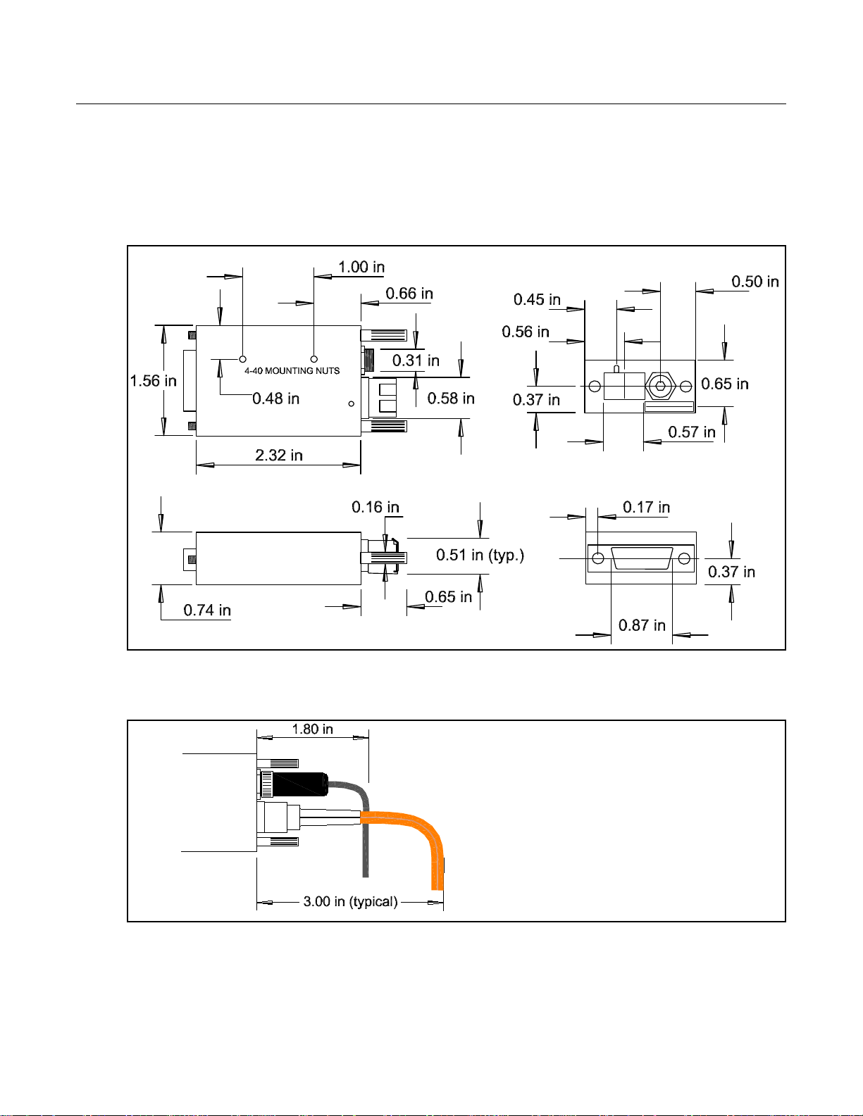
Dimensions
Figure 9 shows typical VisionLink RCX dimensions. The power connector dimension of 0.31 inch is for the standard
power connector; the optional Lemo connector on the fiber version is approximately 0.35 inch.
NOTE Connector dimensions are approximate; for precise dimensions, see the manufacturer’s specificati ons.
Figure 9. Extender dimensions
Figure 10 shows a typical value for cable clearance; the exact value is dependent upon the cable used.
Figure 10. Cable clearance
EDT, Inc. 2016 August 30 16
Page 17

VisionLink RCX Dimensions
Revision Log
Below is a history of modifications to this guide.
Date Rev By Pg(s) Detail
20150521 0000 PH,RH All • Created new guide.
20160812 0001 PH,CH 11-12 • In Resetting or Changing the Operating Mode: Suggested updates (20160722~11:42a,
20160812 0001 PH,CH 13-15 • In Pin Assignments and Power Supply sections, updated power spec from “+4.75 to +24
20160830 0002 PH,CH 15 • Under Pin Assignments > Cable assembly - Lemo to female DB9 RS232 > Table 8 > DB9
from CH, “VL RCX - changing the blink code) were made and ok’d by CH.
V DC” (and, for Lemo to loose wire, “+4.75 to +18 VDC”) to “+4.75 to +28 V DC.”
pin column, deleted “9” and “5.”
EDT, Inc. 2016 August 30 17
 Loading...