

Page 1

User’s Guide
VisionLink F-Series
Camera Link Frame Grabbers
for PCI Express
Date: 2019 April 29
Rev.: 0012
Page 2

EDT, Inc.
2
EDT | Engineering Design Team, Inc.
3423 NE John Olsen Ave
Hillsboro, OR 97124 U.S.A.
Tel: +1-503-690-1234 | Toll free (in U.S.A.): 800-435-4320
Fax: +1-503-690-1243
www.edt.com
TM
EDT
and Engineering Design Team
and copyrights are the property of their respective owners†.
TM
are trademarks of Engineering Design Team, Inc. All other trademarks, service marks,
© 1997-2019 Engineering Design Team, Inc. All rights reserved.
FCC Compliance: EDT devices described herein are in compliance with part 15 of the FCC Rules. Operation is subject to two
conditions: (1) The device may not cause harmful interference, and (2) the device must accept any interference received,
including interference that may cause undesired operation.
This equipment has been tested and found to comply with the limits for a Class A digital device, pursuant to part 15 of FCC Rules.
These limits are designed to provide reasonable protection against harmful interference in a commercial environment. This
equipment generates, uses, and can radiate radio frequency energy and, if not installed and used as described in the user’s
guide, may cause harmful interference to radio communications. Operating this equipment in a residential area is likely to cause
harmful interference, in which case the user will be required to correct the interference at his or her own expense.
Caution: Changes or modifications not expressly approved by Engineering Design Team, Inc. could void your warranty to
operate this equipment.
Page 3

EDT, Inc.
3
Terms of Use Agreement
Definitions. This agreement, between Engineering Design Team, Inc. (“Seller”) and the user or distributor (“Buyer”), covers the
use and distribution of the following items provided by Seller: a) the binary and all provided source code for any and all device
drivers, software libraries, utilities, and example applications (collectively, “Software”); b) the binary and all provided source code
for any and all configurable or programmable devices (collectively, “Firmware”); and c) the computer boards and all other physical
components (collectively, “Hardware”). Software, Firmware, and Hardware are collectively referred to as “Products.” This
agreement also covers Seller’s published Limited Warranty (“Warranty”) and all other published manuals and product information
in physical, electronic, or any other form (“Documentation”).
License. Seller grants Buyer the right to use or distribute Seller’s Software and Firmware Products solely to enable Seller’s
Hardware Products. Seller’s Software and Firmware must be used on the same computer as Seller’s Hardware. Seller’s Products
and Documentation are furnished under, and may be used only in accordance with, the terms of this agreement. By using or
distributing Seller’s Products and Documentation, Buyer agrees to the terms of this agreement, as well as any additional
agreements (such as a nondisclosure agreement) between Buyer and Seller.
Export Restrictions. Buyer will not permit Seller’s Software, Firmware, or Hardware to be sent to, or used in, any other country
except in compliance with applicable U.S. laws and regulations.
For clarification on such laws and regulations, see the website for...
•
U.S. Department of Commerce, Bureau of Industry and Security
https://www.commerce.gov/bureau-industry-and-security
...or, if ITAR status is indicated in the product’s documentation (on the title page or near the beginning), see the website for...
•
U.S. Department of State, Bureau of Political-Military (PM) Affairs, Directorate of Defense Trade Controls (DDTC)
https://www.pmddtc.state.gov/regulations_laws/itar.html
Limitation of Rights. Seller grants Buyer a royalty-free right to modify, reproduce, and distribute executable files using the
Seller’s Software and Firmware, provided that: a) the source code and executable files will be used only with Seller’s Hardware;
b)
Buyer agrees to indemnify, hold harmless, and defend Seller from and against any claims or lawsuits, including attorneys’ fees,
that arise or result from the use or distribution of Buyer’s products containing Seller’s Products. Seller’s Hardware may not be
copied or recreated in any form or by any means without Seller’s express written consent.
No Liability for Consequential Damages. In no event will Seller, its directors, officers, employees, or agents be liable to Buyer
for any consequential, incidental, or indirect damages (including damages for business interruptions, loss of business profits or
information, and the like) arising out of the use or inability to use the Products, even if Seller has been advised of the possibility
of such damages. Because some jurisdictions do not allow the exclusion or limitation of liability for consequential or incidental
damages, the above limitations may not apply to Buyer. Seller’s liability to Buyer for actual damages for any cause whatsoever,
and regardless of the form of the action (whether in contract, product liability, tort including negligence, or otherwise) will be
limited to fifty U.S. dollars ($50.00).
Limited Hardware Warranty. Seller warrants that the Hardware it manufactures and sells shall be free of defects in materials
and workmanship for a period of 12 months from date of shipment to initial Buyer. This warranty does not apply to any product
that is misused, abused, repaired, or otherwise modified by Buyer or others. Seller’s sole obligation for breach of this warranty
shall be to repair or replace (F.O.B. Seller’s plant, Beaverton, Oregon, USA) any goods that are found to be non-conforming or
defective as specified by Buyer within 30 days of discovery of any defect. Buyer shall bear all installation and transportation
expenses, and all other incidental expenses and damages.
Limitation of Liability. In no event shall Seller be liable for any type of special consequential, incidental, or penal damages,
whether such damages arise from, or are a result of, breach of contract, warranty, tort (including negligence), strict liability, or
otherwise. All references to damages herein shall include, but not be limited to: loss of profit or revenue; loss of use of the goods
or associated equipment; costs of substitute goods, equipment, or facilities; downtime costs; or claims for damages. Seller shall
not be liable for any loss, claim, expense, or damage caused by, contributed to, or arising out of the acts or omissions of Buyer,
whether negligent or otherwise.
No Other Warranties. Seller makes no other warranties, express or implied, including without limitation the implied warranties
of merchantability and fitness for a particular purpose, regarding Seller’s Products or Documentation. Seller does not warrant,
guarantee, or make any representations regarding the use or the results of the use of the Products or Documentation or their
correctness, accuracy, reliability, currentness, or otherwise. All risk related to the results and performance of the Products and
Documentation is assumed by Buyer. The exclusion of implied warranties is not permitted by some jurisdictions. The above
exclusion may not apply to Buyer.
Disclaimer. Seller’s Products and Documentation, including this document, are subject to change without notice. Documentation
does not represent a commitment from Seller.
Page 4

EDT, Inc.
4
Contents
Overview ..................................................................................................................................................................... 6
Included Files ....................................................................................................................................................... 6
Power Over Camera Link (PoCL) ........................................................................................................................ 7
Related Resources ............................................................................................................................................... 7
Requirements ............................................................................................................................................................. 8
Installation ................................................................................................................................................................... 8
Setting the Camera Model .......................................................................................................................................... 9
Image Capture and Display GUI ................................................................................................................................. 9
Units, Connectors, and Channels ............................................................................................................................. 11
LEDs ......................................................................................................................................................................... 12
Serial Communication ............................................................................................................................................... 12
At Initialization .................................................................................................................................................... 12
From Command Line ......................................................................................................................................... 12
From EDT GUI ................................................................................................................................................... 12
From Your Application ........................................................................................................................................ 13
From Camera Manufacturer’s Application ......................................................................................................... 13
Example and Utility Applications .............................................................................................................................. 13
Triggering .................................................................................................................................................................. 16
No Triggering – Freerun (Continuous) ............................................................................................................... 16
Triggered by EDT Board (On-Demand) ............................................................................................................. 17
Triggered by EDT Board (Fixed Period)............................................................................................................. 17
Pulse-Width Triggered (Controlled or Level) ...................................................................................................... 18
External Trigger Direct to Camera ..................................................................................................................... 18
External Trigger Passthrough ............................................................................................................................ 18
External Triggering Pins ..................................................................................................................................... 19
Simulation and Testing ............................................................................................................................................. 20
Programming ............................................................................................................................................................ 21
Building or Rebuilding an Application ................................................................................................................ 21
Compiling vlviewer ............................................................................................................................................. 22
Firmware: FPGA Configuration (.bit) Files ................................................................................................................ 22
Checking and Loading the Firmware ................................................................................................................. 23
Corrupted Firmware ........................................................................................................................................... 24
Troubleshooting ........................................................................................................................................................ 24
Board Not Seen .................................................................................................................................................. 25
Problems With Software Installation .................................................................................................................. 25
Corrupted Images, Slow Acquisition, Timeouts, Data Loss ............................................................................... 26
Problems With Bandwidth .................................................................................................................................. 27
Problems Acquiring Images With EDT Applications .......................................................................................... 27
Problems With Your Applications ....................................................................................................................... 28
Problems With Threads ...................................................................................................................................... 28
Problems With Firmware .................................................................................................................................... 28
Appendix A: Pin Assignments................................................................................................................................... 29
Appendix B: Diagrams – Boards and Cabling .......................................................................................................... 30
VisionLink F-Series Frame Grabbers ................................................................................................................. 30
F1 and F4 ..................................................................................................................................................................... 30
Additional External Inputs .................................................................................................................................. 31
Via Berg or Optional Lemo Connector. ........................................................................................................................ 31
Via Optional Cable Assembly ....................................................................................................................................... 31
Via Ribbon Cabling and D9 Connectors....................................................................................................................... 32
Appendix C: Timestamping....................................................................................................................................... 33
Camera Configuration File Directives ................................................................................................................ 33
Page 5

EDT, Inc.
5
Footer Format .................................................................................................................................................... 33
IRIG API ............................................................................................................................................................. 35
Revision Log ............................................................................................................................................................. 37
Page 6

VisionLink F-series
Overview
EDT, Inc.
2019 April 29
6
Product
Bus spec
Camera Link
Part
Product
name
x lanes
modes
number
description
VisionLink F1
PCIe x1
Base
019-14853
Half-height backpanel, 1 SDR
019-14854
Half-height backpanel, 2 SDRs, 128 MB DDR3, IRIG-B
019-14836
Full-height backpanel, 1 SDR
019-14852
Full-height backpanel, 2 SDRs, 128 MB DDR3, IRIG-B, Lemo
VisionLink F4
PCIe x4
Base–
TBD
Half-height backpanel
full
019-14856
Full-height backpanel
019-14857
Full-height backpanel, Lemo
VisionLink F-series
Overview
This guide covers EDT VisionLink F-series frame grabbers, which provide fast, high-resolution image capture and DMA
between an external Camera Link camera and a host computer.
These frame grabbers are designed for PCIe Gen2 but can work with other PCIe generations; however, performance
is limited by the generation of the board or slot, whichever is lower.
Companion products include remote camera extenders (RCX) over fiber; for details, see Related Resources on page 7.
Available configurations for the F-series are shown in Table 1.
Table 1. VisionLink F-series frame grabbers for Camera Link
Included Files
For the above products, your EDT installation package includes README files for quick start information and special
cases (README.*), as well as device drivers for supported operating systems and source code and binaries for...
•
GUI capture and display applications (vlviewer, pdvshow)
•
Standalone initialization applications (initcam, camconfig)
•
Command-line capture and display applications (take, simple_take, simplest_take, simple_*)
•
Command-line serial communication tool (serial_cmd)
•
Diagnostic tools (pciload, pciediag, dvinfo, pdb)
•
API libraries (libpdv, libedt, and associated source files)
•
Makefiles for Windows and Linux (makefile)
•
Visual Studio project and solution files (*/*.vcproj, */*.sln)
•
Camera configuration files (camera_config/*.cfg)
•
Board firmware files (flash/* directories)
•
Windows silent install / uninstall example batch files (wdf/install/*.bat)
Page 7

VisionLink F-series
Overview
EDT, Inc.
2019 April 29
7
For detailed descriptions of selected programs, see Example and Utility Applications on page 13. For a more complete
list of files and quick-start information, consult README.pdv in your EDT installation package (see Installation on
page 8). For programming information, consult the EDT API (see Related Resources on page 7).
Power Over Camera Link (PoCL)
VisionLink frame grabbers support Power over Camera Link (PoCL) via the MSP430 using safe power. PoCL is enabled
via software (implementation TBD). For PoCL pin assignments, see Appendix A: Pin Assignments on page 29.
Related Resources
To find product-specific information that is related to a particular EDT product, go to .edt.com and open the relevant
product page. There you’ll see links to that product’s datasheet (specifications), user’s guide, and other resources.
In addition, the resources below may be helpful or necessary for your applications.
EDT Resources
•
Application programming interface (API) edt.com/dv_api
•
Installation packages (Windows, Linux) edt.com/download-hub
•
VisionLink F1 datasheet / specifications edt.com/product/visionlink-f1
•
VisionLink F4 datasheet / specifications edt.com/product/visionlink-f4
•
Companion products edt.com/vision
•
Camera configuration guide edt.com/downloads/DeviceConfig.pdf
•
Firmware reference edt.com/downloads/dv-c-link-firmware-reference.pdf
•
Cabling options edt.com/clink-cables
•
Tutorial video(s) edt.com/vision
Third-Party Resources
•
PCI Express (PCIe) specifications www.pcisig.com
•
Camera Link specifications www.visiononline.org
•
IRIG-B specifications irigb.com
Page 8

EDT, Inc.
2019 April 29
8
VisionLink F-series
Requirements
Bus type*
Throughput (observed)
Cabling
OS
VisionLink F1
x1 PCIe, Gen2
400MB/s
Standard Camera Link SDR
NOTE: Cabling can be from EDT or a third party.
For more documentation on cabling / pins, see
Related Resources on page 7 and Appendix A:
Pin Assignments on page 29.
Windows,
Linux
x1 PCIe, Gen1
175MB/s
VisionLink F4
x4 PCIe, Gen2
1000MB/s
x4 PCIe, Gen1
700MB/s, preliminary
Requirements
EDT boards are high-speed DMA devices that require adequate bandwidth for reliable operation. The requirements will
vary by camera (since different cameras run at different speeds), so you should select and configure your camera and
system with the proper requirements in mind, as shown in Table 2.
Table 2. Requirements for I/O, bus type, throughput, cabling
*
For bus type, observe these considerations to optimize performance...
–
Typically, these products will not work in a bus slot dedicated to graphics (display) cards.
–
Typically, these products will work in a bus slot with more, but not one with fewer, lanes than the number given here.
–
Typically, although these products will work in a bus slot newer than PCIe Gen2 (such as Gen3), performance still will not exceed
Gen2 specifications.
For details on requirements and bandwidth issues, see Problems With Bandwidth on page 27.
Installation
“Installation directory” in this guide refers to the directory in which your EDT installation package was saved.
Unless you opted to save it elsewhere, the package is saved in the default installation directory specified below.
•
The Windows default installation directory is: C:\EDT\pdv
•
The Linux default installation directory is: /opt/EDTpdv
1.
Uninstall any previously installed EDT installation packages.
2.
To use the latest possible package without creating version incompatibility issues, do one of the following...
—
For a new application, download the latest package from the EDT installation disk (included with the product),
or from www.edt.com (see Related Resources on page 7).
To install your frame grabber software, follow the steps below.
—
For an application running third-party software, use the EDT installation package version with which the software was built, or recompile / relink the application with the latest package (see Related Resources on page 7).
—
For a new board used in applications developed for earlier boards (e.g., EDT DV/a series), recompile / relink
the application with libraries / header files from an EDT device driver / SDK, version 5.4.5.8 or later.
3.
Follow the installation instructions from your camera manufacturer and your host computer manufacturer.
4.
Connect the frame grabber, using the cabling specified in Requirements on page 8.
5.
To verify that the driver is installed and the board is recognized, run pciload from the command line (for details,
see Example and Utility Applications on page 13).
NOTE If you need to provide an EDT silent Windows software installation as part of your own installation process, see
the EDT Windows batch (.bat) files in the wdf\install subfolder of the EDT installation folder. The comments
in the files explain how they can be used.
Page 9

EDT, Inc.
2019 April 29
9
VisionLink F-series
Setting the Camera Model
OS
Configuration via GUI
Configuration via command line
Windows
Click the desktop icon for vlviewer.
When the camera selection dialog box appears, select
your camera. After initial setup, access this dialog box
any time via the Camera>Setup menu.
From the pdv utilities command shell, invoke the
initcam utility...
initcam -f camera_config\filename.cfg
...where filename is the camera configuration file
that matches your camera model and operating mode.
For specifying a non-default unit and channel and other
options, see initcam (Example and Utility
Applications on page 13) and the Camera
Configuration Guide (Related Resources on page 7).
Linux
First, build vlviewer (see Compiling vlviewer on
page 22). Then, in the installation directory (see
Installation on page 8), enter...
vlviewer
When the camera selection dialog box appears, select
your camera. After initial setup, access this dialog box
any time via the Camera>Setup menu.
From a terminal window, navigate to the installation
directory and follow the procedure for Windows,
replacing “\” with “/”.
If you do not have “.” in your path, add “./” before
each command – for example...
./initcam -f camera_config/file.cfg
Setting the Camera Model
Your EDT installation package provides example configuration files for various camera models; if no file is provided for
your camera, or if you wish to modify the directives of an existing configuration file, consult the EDT Camera
Configuration Guide (see Related Resources on page 7).
After installing the board and its driver, configure it for the camera you will use.
Next, initialize (configure) the driver for your camera model, using one of the methods in Table 3.
Table 3. Configuring the driver for your camera
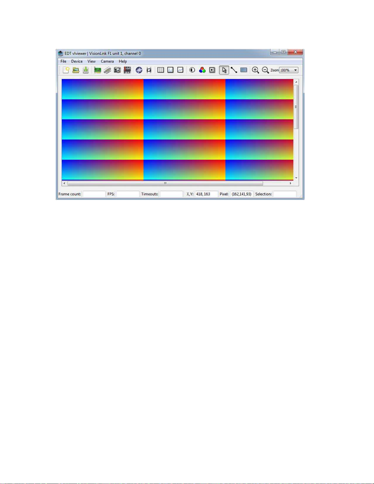
Image Capture and Display GUI
Your EDT software contains the GUI application vlviewer, a GUI application which allows you to:
•
Configure the frame grabber for a specific camera.
•
Capture, display and save (.bmp, .tif, .jpg or .raw) images from cameras connected to the frame grabber.
•
Perform image processing and analysis on captured image data.
•
Communicate with the camera via serial.
•
Display information about the frame grabber hardware and device driver.
The Windows version of vlviewer is shown in Figure 1.
Page 10
EDT, Inc.
2019 April 29
10
VisionLink F-series
Image Capture and Display GUI
Figure 1. Windows version – vlviewer
NOTE In Windows, the command line is a property of the icon.To use an icon to access a unit or channel other than 0 (the
To run the GUI...
•
For Windows: Click the vlviewer desktop icon, or enter vlviewer at a command prompt.
•
For Linux: Compile vlviewer (see Compiling vlviewer on page 22); then, in the installation directory (see Instal-
lation on page 8), enter...
vlviewer
To invoke with other than the default (0,0) unit and channel, run...
vlviewer -pdvU_C
...replacing U with the unit number (useful if you have more than one VisionLink device) and C with the channel
number for multichannel devices (see Units, Connectors, and Channels on page 11).
For example, to run the GUI using board 0, channel 1, run...
vlviewer -pdv0_1
This example is useful if, for instance, you are using one board with two base-mode cameras and you want the GUI to
access the camera on channel 1.
default): copy and rename the vlviewer icon; then change its shortcut properties to use the command line with the
option -pdvU_C where U is the unit and C is the channel.
If the image window shows incorrect data (usually because the camera model has been changed since the last
configuration), select Camera > Setup and choose the correct camera model.
If you have not yet configured the device for your camera, select your camera or simulator from the list and click OK.
To access camera controls, use the GUI toolbar and menus. For details on available options, run...
vlviewer --help
...or bring up vlviewer and select the Help menu.
Page 11
EDT, Inc.
2019 April 29
11
VisionLink F-series
Units, Connectors, and Channels
Definition
Usage and Enumeration
unit
physical board
If you install one board in your host system, the system will assign the default unit number (0) to
that board. If you install multiple boards, the system will assign a unique unit number to each
board, starting with 0 (the sequence is system-dependent). Typically, the unit number is an
argument when invoking an application (such as take or vlviewer) or a parameter passed
into one of the EDT subroutines.
connector
physical Camera
Link connector
Each VisionLink board has one or two SDR connectors and one simulation channel.
•
In base mode, each camera requires one SDR connector on the EDT board, and each connector provides one channel. Therefore, in base mode, an EDT frame grabber with two connectors has two channels.
•
In medium or full mode, each camera requires two SDR connectors on the EDT board. In this
case, the two connectors work together to support one channel.
The software enumerates each SDR connector starting from the PCIe bus. So the first (primary)
connector is “0” and the next (secondary) connector is “1.” The simulator channel is “2.”
See Simulation and Testing on page 20.
channel
channel or,
sometimes,
simulation channel
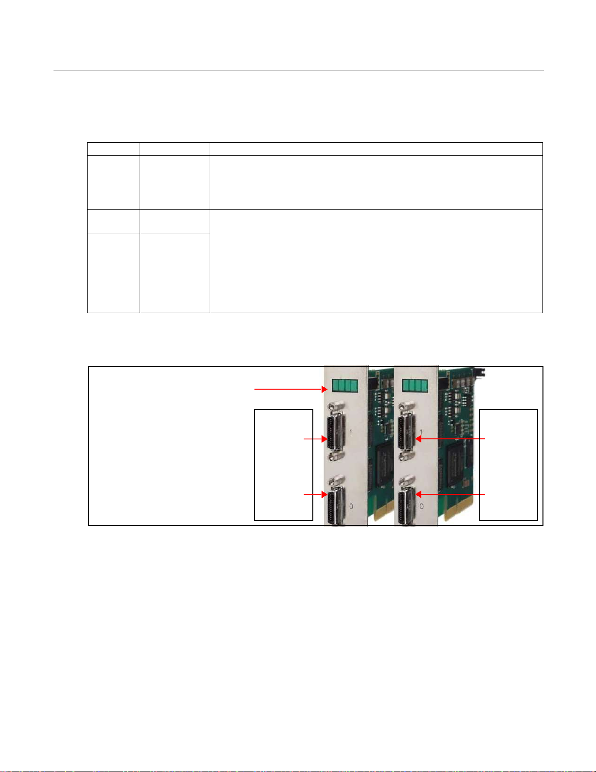
LEDs
LED enumeration is 0, 1, 2, 3 (left to right
in the board’s typical vertical orientation).
0 1 2 3
Units & Connectors
Unit enumeration is system-dependent,
starting with unit 0.
Unit 0,
Connector 1
(secondary
connector)
Unit 1,
Connector 1
(secondary
connector)
Connector enumeration starts at 0 with
the connector nearest the PCIe bus. Unit 0, Unit 1,
Connector 0 Connector 0
(primary (primary
connector) connector)
Units, Connectors, and Channels
This section covers how to work with multiple units, connectors, and channels, defined and used as shown in Table 4.
Table 4. Definition, usage, and enumeration
Figure 2 illustrates enumeration. Units (boards), connectors, and channels are always enumerated from 0. Figure 2 also
shows the status indicator LEDs (see LEDs on page 12), which are enumerated in the same way.
Figure 2. Illustration of enumeration
If you are using multiple EDT boards (units), or multiple connectors on a single EDT board, the software assigns a
unique handle to represent each unit and connector. Unless you specify a different unit number, connector number, or
both, all EDT example and utility applications will default to unit 0, connector 0.
The way that you address the appropriate unit and channel will depend on what you are doing.
•
In the EDT GUI (vlviewer or pdvshow), use -pdvU_C (see Image Capture and Display GUI on page 9.
•
In the EDT example and utility applications, use -u unit and -c channel (see Example and Utility Applica-
tions on page 13).
•
In the EDT API, use pdv_open_channel(..., unit, channel). For each device, the open routine will return
a pointer to the structure that represents the opened device (unit and channel); this pointer appears in EDT examples and documentation as pdv_p. Each unit / channel combination can be opened and manipulated independently by passing the appropriate pointer to the library subroutines. For details, consult the EDT API (see Related
Resources on page 7).
Page 12

EDT, Inc.
2019 April 29
12
VisionLink F-series
LEDs
LED #
Connector #
Status
0 0
Pixel clock: on = present; off = absent
1 0 PoCL output:: on = 12V; off = GND; fast blink = error; slow blink = floating / open / sensing
2 1
Pixel clock: on = present; off = absent
3 1 PoCL output:: on = 12V; off = GND; fast blink = error; slow blink = floating / open / sensing
LEDs
As shown in Figure 2, each frame grabber’s backpanel has four LEDs (0, 1, 2, 3, left to right) to show status, as below.
Table 5. LED behavior and significance
Serial Communication
Most cameras have a manufacturer-defined serial command set for camera control and status. To utilize this capability,
EDT boards implement serial transmit and receive using standard serial lines as defined by the Camera Link standard.
You can use serial communication in a number of ways, as discussed below.
At Initialization
As mentioned in Installation on page 8, the initialization process uses directives in a configuration file to set the board
registers and the driver variables to match your camera model and your operating mode. Additional directives
(especially serial_baud, serial_init, serial_binit, and other serial_* directives) can be used to
send serial commands when the system is initialized. These are described in the EDT Camera Configuration Guide (see
Related Resources on page 7).
EDT provides several example configuration files that contain the serial commands needed to put a camera into the
desired mode. You can edit these commands or copy them to a new configuration file.
For suggestions, see comments in the example configuration files camera_config/genericXcl.cfg (where X is
replaced by a specific bits-per-pixel value – for example, generic8cl.cfg) in the EDT installation package.
From Command Line
The command-line utility serial_cmd, described in serial_cmd on page 15, allows you to send serial commands to
a camera and receive its response, in either ASCII or hexadecimal format. Command-line help also can be accessed
by entering serial_cmd --help.
If you wish to incorporate this functionality in your own application, see the source code provided in serial_cmd.c
in the EDT installation package.
From EDT GUI
In vlviewer, from the Camera menu, select Programming. The resulting dialog allows you to send and receive serial
commands from the camera. For details, see Image Capture and Display GUI on page 9.
Page 13

EDT, Inc.
2019 April 29
13
VisionLink F-series
Example and Utility Applications
From Your Application
To see all of the routines needed for user applications to send and receive serial commands: In the EDT API (see
Related Resources on page 7), follow the link to the EDT digital imaging library, and then — under Modules at the
bottom of the page — to Communications / Control.
From Camera Manufacturer’s Application
Most Camera Link camera makers supply a Windows-based graphical camera control application that lets you send and
receive serial commands using a board-specific serial dynamic link library (DLL). Your EDT installation package
provides a DLL named clseredt.dll which, per the Camera Link 2.0 specification, is installed at...
•
%PROGRAMFILES%\Cameralink\Serial (64-bit version); or
•
%PROGRAMFILES(X86)%\CameraLink\Serial (32-bit version)
Camera GUIs typically provide some method for specifying the DLL pathname; for details, see your camera
documentation.
If it becomes necessary to rename the file or copy it to a different location, be sure to recopy any newer versions of the
NOTE Some camera manufacturers' control applications do not use this DLL method but instead depend on COM port
file to the appropriate location when you reinstall the EDT installation package.
emulation for serial communication. In such cases, use the provided COM port emulation method; for details, see
README.pdvcom in your installation directory.
Example and Utility Applications
EDT provides a variety of example, utility, and diagnostic applications. All can be run from the command line, using Unixstyle options and arguments.
To help those developing applications, EDT provides C source code for all of the examples. The source code file is the
name of the application with a .c extension (e.g., “take.c”). Starting with the source for simple_take or
simplest_take is recommended.
The most commonly useful options for these programs are described below. Placeholders shown in italics should be
replaced with your own values. For a complete list of usage options, at the command line, enter the application name
pciload
setdebug
with the --help option to display the help message.
Used to query the boards or, optionally, to update and verify the board’s flash PROM. After installation, you may want
to run pciload with no arguments and review the output to help verify that the board and driver did install correctly.
To use pciload to update and verify the flash PROM, see Firmware: FPGA Configuration (.bit) Files on page 22.
A debug and diagnostic utility. The options shown here may be useful to you. Options not shown here, as a rule, are
specific to driver internals and are useful (and safe) only with guidance from EDT engineers.
-u unit The unit number, if multiple boards are installed; default is 0 (first board).
-c channel The channel, on multichannel boards; default is 0 (first channel).
-d 0 Unique to setdebug. Displays current board register values.
-v Unique to setdebug. Displays version information for library and driver.
-h Displays full list of options.
Page 14

EDT, Inc.
2019 April 29
14
VisionLink F-series
Example and Utility Applications
initcam
take
Command-line utility that initializes the board and device driver for a specific camera. It initializes board registers; sets
various parameters (width, height, depth, etc.) to specific values; and optionally sends serial initialization commands to
the camera from the referenced configuration file. Configuration files are in your EDT installation package under
camera_config. The EDT camera selector GUI applications (vlviewer, pdvshow) are simply wrappers to provide a
way to select the correct file, then shell out to call initcam. To initialize from your own application code, you can use
initcam.c as example code.
For a detailed description of configuration files and directives, consult the Camera Configuration Guide (see Related
Resources on page 7).
Several of the most useful options are...
-u unit The unit number, if multiple boards are installed; default is 0 (first board).
-c channel The channel, on multichannel boards; default is 0 (first channel).
-f pathname The (required) name of the configuration file to use for initialization.
For example...
initcam -f camera_config/generic8cl.cfg
Used to acquire images and (optionally) save them to files. Though it does not display the images, it does provide many
other options, making it a useful diagnostic tool. The source also shows how to change camera settings such as
integration time; tune image acquisition in certain ways; and detect errors.
Several of the most useful options are...
-u unit The unit number, if multiple boards are installed; default is 0 (first board).
-c channel The channel, on multichannel boards; default is 0 (first channel).
-b file The base name of the file in which to save the image, in Windows bitmap format
for all systems (note – in EDT software packages later than 5.3.3.3, this option
always will create files in Windows bitmap format, regardless of which operating
system you are using). If only one image is taken, this is the filename; otherwise a
two-digit number is appended to each file, starting with 00. The appropriate suffix
is automatically added.
-f file The name of the file in which to save the image, in raw format. The file includes
only raw image data, with no formatting information.
-l loopcount The number of consecutive pictures you wish to take. The default is one.
-N numbufs The number of ring buffers (default is 1). A ring buffer is a portion of host memory
preallocated for DMA and used in round-robin fashion. A setting of four optimizes
pipelining — one ring buffer currently acquiring data, one ready for data, one
getting ready, and one backup.
-v Turns on verbose mode. The default is off.
As an example, to acquire 100 images as quickly as possible using four ring buffers, without saving to files, enter...
take -N 4 -l 100
As another example, if you have one VisionLink board connected to two base-mode cameras and you wish take to
use the camera on channel 1, enter...
take -u 0 -c 1 -N 4 -l 100
Page 15

EDT, Inc.
2019 April 29
15
VisionLink F-series
Example and Utility Applications
simple_take
Shows how to use the API to acquire images from a camera linked to the board and (optionally) save the images to files.
To add image acquisition to an application, EDT recommends starting with this example, which shows how to use the
ring buffer routines to improve performance by pipelining image acquisition and processing.
Several of the most useful options are...
For example, to acquire four images as fast as possible using four ring buffers, saving each to files named
picture00.bmp through picture03.bmp, enter...
-u unit The unit number, if multiple boards are installed; default is 0 (first board).
-c channel The channel, on multichannel boards; default is 0 (first channel).
-b file The base name of the file in which to save the image. If only one image is taken,
this is the filename; otherwise a two-digit number is appended to each file, starting
with 00. The appropriate suffix is automatically added.
-l loopcount The number of consecutive pictures you wish to take. The default is one.
-N numbufs The number of ring buffers — by default, one. (A ring buffer is a portion of host
memory preallocated for DMA and used in round-robin fashion.) A setting of four
optimizes pipelining — one ring buffer currently acquiring data, one ready for data,
one getting ready, and one backup.
simple_take -N 4 -l 4 -b picture
simplest_take
The simplest example application, showing only how to open the device, acquire an image, check for timeouts, and
close the device. For simplicity, there is no optimization for pipelining, no processing or extended error checking.
simplest_take reports a successful image acquisition, or any errors that occurred — useful for testing.
simple_sequence
Like simple_take but, instead of capturing and saving one file at a time, it captures a finite number of images (limited
to available memory) into memory and then writes them all out at once.
serial_cmd
Sends serial commands to a camera through the board, using calls to routines in the API. By default, the application
starts in command mode: the final argument to serial_cmd is the command to send to the camera. Delimit this
command with either single or double quotation marks, but be consistent. For example...
serial_cmd "MDE?"
If you omit the command argument, the application enters interactive mode, in which you can type one command per
line. To quit the application, enter Control-C.
Several of the most useful options are...
-u unit The unit number, if multiple boards are installed; default is 0 (first board).
-c channel The channel, on multichannel boards; default is 0 (first channel).
-x Treats the command argument as a hexadecimal number, which is sent to the
For example (command mode usage)...
% serial_cmd "MDE?" (Redlake "Query Mode" command)
camera without terminating nulls or carriage returns. The default is ASCII with a
terminating carriage return added.
Page 16

EDT, Inc.
2019 April 29
16
VisionLink F-series
Triggering
dvinfo
MDE TR (camera response)
%
For example (interactive mode usage)...
% serial_cmd
>MDE? (Redlake "Query Mode" command)
MDE TR (camera response)
>
% serial_cmd -x (for hexadecimal arguments)
> 03 06 02 (camera-dependent command)
> Control-C (end the program)
To access a camera on channel 1, enter...
% serial_cmd -u 0 -c 1 "MDE?"
(Redlake "Query Mode" command)
MDE TR (camera response)
%
Gathers board-specific and system-specific technical data, runs various diagnostics, and writes the results to
dvinfo.out in the current directory. Use the resulting ASCII text file to diagnose problems yourself, or send the file
to EDT for technical support.
To run dvinfo...
1.
Connect and power on the camera.
2.
If possible, initialize the board with initcam or vlviewer.
3.
Close all VisionLink applications (including initcam, vlviewer, pdvshow, etc.).
4.
Run dvinfo. If multiple boards are installed, you may find it helpful to add the optional flag...
-u unit
...replacing unit with the unit number. The default is 0 for the first board (for details, see Units, Connectors, and
Channels on page 11).
Triggering
EDT provides configuration files for most cameras running in freerun mode (i.e., no triggering), and also some files for
cameras running in triggered or pulse-width modes. This section describes common triggering modes supported by
EDT, with abbreviated information on configuration file directives and subroutines. For more complete information,
NOTE If you have issues, consult Troubleshooting on page 24.
No Triggering – Freerun (Continuous)
consult the EDT Camera Configuration Guide and API (see Related Resources on page 7) and your camera manual.
In this mode, the camera acquires images continuously without initiating or passing through any trigger or expose
signals. Exposure time is controlled by the camera and typically is set via a camera-specific serial command.
Page 17

EDT, Inc.
2019 April 29
17
VisionLink F-series
Triggering
For area or line scan cameras, use the following information...
Configuration file directives
MODE_CNTL_NORM: 00 (default)
serial_init: Camera-specific serial command(s) to initialize for freerun. Use as
needed (usually not needed because most cameras power on in freerun by default).
serial_exposure: Camera-specific serial command to set the exposure time; for
example, use "set" for the Dalsa 1M60.
API subroutine
pdv_set_exposure(), Camera-specific range and units.
Triggered by EDT Board (On-Demand)
In this mode, the camera sends a 1-millisecond trigger pulse over a camera control line, typically CC1, each time a
request for acquisition is made – such as when pdv_start_images() is called. Exposure time is controlled by the
camera, and typically is set via a camera-specific serial command.
For area or line scan cameras, use the following information...
Configuration file directives
MODE_CNTL_NORM: 10
method_camera_shutter_timing: AIA_SER (default)
serial_init: Camera-specific serial argument to enable triggering via CC1.
serial_exposure: Camera-specific serial command to set the exposure time; for
example, use "set" for the Dalsa 1M60.
API subroutine
pdv_set_exposure(), Camera-specific range and units.
Triggered by EDT Board (Fixed Period)
In this mode, the board sends a fixed periodic trigger signal over a camera control line, typically CC1, for each frame or
line of image data.
For area scan cameras, use the following information...
Configuration file directives
MODE_CNTL_NORM: 10
CL_CFG2_NORM: The default is 00, which selects current channels counter; use 80 to
select other channels counter (i.e., if synchronized trigger output is desired).
method_frame_timing: FMRATE_ENABLE
frame_period: Microsecond units (range 0–16777215).
photo_trig: 1
serial_init: Camera-specific serial command to enable triggering via CC1.
API subroutine
pdv_set_frame_period(), Microsecond units (range 0–16777215).
For line scan cameras, use the following information...
Configuration file directives
MODE_CNTL_NORM: 10
CL_CFG_NORM: 14
CL_CFG2_NORM: The default is 00, which selects current channels counter; use 80 to
select other channels counter (i.e., if synchronized trigger output is desired).
xregwrite_16: 40
method_frame_timing: FMRATE_ENABLE
frame_period: Microsecond units (range 0–16777215).
serial_init: Camera-specific serial command to enable triggering via CC1.
API subroutine
pdv_set_frame_period(), Microsecond units (range 0–16777215).
Page 18

EDT, Inc.
2019 April 29
18
VisionLink F-series
Triggering
Pulse-Width Triggered (Controlled or Level)
In this mode, exposure duration is determined by how long the camera control line, typically CC1, is held TRUE (high).
For area scan or line scan cameras, use the following information...
Configuration file directives
API subroutine
For line scan cameras with very fast shutters accepting exposure times in microseconds, use the argument 100US for
method_camera_shutter_timing in order to set pdv_set_exposure() for microseconds, not milliseconds...
Configuration file directives
API subroutine
MODE_CNTL_NORM: 10
method_camera_shutter_timing: AIA_MCL
default_shutter_speed: Millisecond units (range 0–25500).
serial_init: Camera-specific serial command to enable pulse-width exposure control
via CC1.
pdv_set_exposure(), Millisecond units (range 0–25500).
MODE_CNTL_NORM: 10
method_camera_shutter_timing: AIA_MCL_100US (to change to
miicroseconds)
default_shutter_speed: Microsecond units (range 0–25500).
serial_init: Camera-specific serial command to enable pulse-width exposure control
via CC1.
pdv_set_exposure(), Microsecond units (range 0–25500).
External Trigger Direct to Camera
In this mode, a trigger is sent from an external source directly to the camera, bypassing the board. The board can be
configured as in freerun mode; however, be aware of the Note on Software Timeouts below.
For area scan or line scan cameras, use the following information...
Configuration file directives
API subroutine
MODE_CNTL_NORM: 00
user_timeout: See Note on Software Timeouts below.
pdv_set_timeout(), Millisecond units (range 0–65535).
External Trigger Passthrough
Note on Software Timeouts
If your application experiences timeouts it is safe to ignore them, but if you do, you won’t know if they were caused by
a problem or by the gap length between triggers. To avoid timeouts due to gap length, do one of the following...
•
If the maximum gap length between triggers is known: Enter a user_timeout value which exceeds that value.
•
If application blocking is acceptable: Enter a user_timeout value of zero (user_timeout: 0)to tell the ap-
plication never to time out but instead to keep waiting for the next trigger.
In this mode, a trigger is sent from an external source directly to the board, which passes it to the camera on a camera
control line, typically CC1.
Page 19

EDT, Inc.
2019 April 29
19
VisionLink F-series
Triggering
For area scan cameras, use the following information...
Configuration file directives
MODE_CNTL_NORM: A0
xregwrite_16: Use optionally to select trigger input. The default is trigger input 0 but if
trigger input 1 is desired, use 80. For details, consult the Firmware Addendum, register 0x10
(see Related Resources on page 7).
user_timeout: See Note on Software Timeouts in External Trigger Direct to Camera.
serial_init: Camera-specific serial command to enable triggering via CC1.
API subroutine
pdv_set_timeout(), millisecond units (range 0–65535)
For line scan cameras using normal external trigger passthrough, use the following information...
Configuration file directives
MODE_CNTL_NORM: A0
CL_CFG_NORM: 04
continuous: 1
xregwrite_16: Use optionally to select trigger input. The default is trigger input 0 but if
trigger input 1 is desired, use 80. For details, consult the Firmware Addendum, register 0x10
(see Related Resources on page 7).
photo_trig: 1
user_timeout: See Note on Software Timeouts in External Trigger Direct to Camera.
serial_init: Camera-specific serial command; enables triggering via CC1.
API subroutine
pdv_set_timeout(), millisecond units (range 0–65535)
For line scan cameras using external trigger passthrough with acquisition arming (not supported for area scan), the
information is similar to the above. A TTL signal is sent from an external source to the board via trigger 0 and then is
passed from the board to the camera via a camera control line (typically CC1) to trigger line output. Additionally, a
secondary TTL signal is sent from an external device to the board via trigger 1, which arms the board for acquisition.
For example, the “A” pulse from an encoder is input on trigger 0 and passed through to the camera via a camera control
line (typically CC1), thus triggering a line to be output from the camera. Additionally, the index pulse from the encoder
is input on trigger 1 to arm or rearm the board for acquisition, ensuring that acquired images are synchronized to the
encoder’s rotational position. The acquired image always starts at the encoder index. Use the following information...
Configuration file directives
MODE_CNTL_NORM: A0
CL_CFG_NORM: 04
CL_CFG2_NORM: 04
continuous: 1
photo_trig: 1
user_timeout: See Note on Software Timeouts in External Trigger Direct to Camera.
serial_init: Camera-specific serial command to enable triggering via CC1.
API subroutine
pdv_set_timeout(), Millisecond units ((range 0–65535)
External Triggering Pins
The pins to which you connect the trigger source are shown in Appendix B: Diagrams – Boards and Cabling.
With two cameras, trigger 0 can trigger both cameras, or triggers 0 and 1 can trigger cameras 0 and 1 independently;
for details on setting the bits, refer to the directive xregwrite_16 or consult the Firmware Addendum (see Related
Resources on page 7), register 0x10, bit 7.
Fire the trigger by applying a TTL signal lasting at least 200 nanoseconds to these pins, which in turn will output a signal
of the appropriate level to a camera control line, typically CC1.
Page 20

EDT, Inc.
2019 April 29
20
VisionLink F-series
Simulation and Testing
The two pins of each trigger drive a Fairchild HCPL062N optocoupler through a 130-ohm series resistor. This
optocoupler is provided to allow coupling to electromechanical systems in which major ground spikes can occur when
electrical devices such as motors, for example, turn on or off.
Simulation and Testing
In addition to the physical channels 0 and 1, each VisionLink frame grabber has a "phantom" channel 2 that reads selfgenerated sample data, useful for testing the board hardware and software with no camera attached. This channel uses
a simple counter to generate 16-bit pixel data; the pixels start as black and fade to white, as shown in Figure 3.
Figure 3. Simulated channel 2 test image in vlviewer
To use the channel 2 simulator with vlviewer...
1.
Start the application with, for example...
vlviewer -pdv0_2
2.
Select the Camera > Setup menu item.
3.
Select the desired configuration.
Page 21

EDT, Inc.
2019 April 29
21
VisionLink F-series
Programming
NOTE For general testing, use one of the genericXXcl.cfg files provided with your board.
To use the channel 2 simulator with your own application...
1.
Use the initialization application initcam, specifying channel 2 and the camera configuration file for your cam-
era. From a command prompt, enter...
initcam -c 2 -f camera_config/yourCamera.cfg
...replacing yourCamera with the appropriate configuration file name for your camera and application.
2.
Open the device with a call to pdv_open_channel and pass it NULL for the device, your value for the unit
number (board), and 2 for the channel – as in this example (showing a unit number of 0)...
PdvDev *pdv_p = pdv_open_channel(NULL, 0, 2);
The pointer returned from this call points to the simulated data; any image acquisition calls, such as
pdv_wait_image, that pass this pointer will access the simulated data.
Because data is generated as fast as possible, you can also use the channel 2 simulator to measure the maximum bus
bandwidth, using the utility application cl_speed. This utility takes the unit number as an argument and begins
channel 2 simulation on the specified board; it then reports the data speeds achieved.
Programming
EDT installation packages include libraries, examples and C / C++ source code that can be used by programmers to
NOTE To interface to the VisionLink board, use subroutines from the EDT digital imaging library (libpdv) and, if
Building or Rebuilding an Application
NOTE Applications which access EDT boards must be compiled and linked to match the platform in use (32- or 64-bit).
modify and develop applications for EDT VisionLink frame grabbers and related devices.
EDT provides a common application programming interface (API) for all supported operating systems, so an application
written for one EDT product is designed to work with other EDT products with minimal modification; any exceptions –
such as for various operating systems – are noted in this guide.
necessary, from the EDT DMA library (libedt); routines in both libraries are documented in the EDT API.
—
The EDT digital imaging library pdv_ subroutines provide a C language interface to your VisionLink board,
and it also handles error recovery, bookkeeping, and camera shutter triggering and timing. EDT recommends
using it for all programming specific to VisionLink products.
—
The lower-level EDT DMA library edt_ subroutines should be accessed directly only when they provide need-
ed functionality that is not provided in the EDT digital imaging library.
All of these resources are provided in your EDT installation package (see Related Resources on page 7).
EDT’s installation package includes C source and executables for all of the provided examples, diagnostics, and utilities.
To build or rebuild a program, use a build method which is appropriate for your operating system, as shown in Table 6.
Applications linked with 32-bit EDT libraries will not run correctly on 64-bit systems, or vice versa. The EDT driver
/ software installation script detects whether the system is running 32- or 64-bit, and installs the appropriate files.
Page 22

EDT, Inc.
2019 April 29
22
VisionLink F-series
Firmware: FPGA Configuration (.bit) Files
Windows
Linux
Compiler
Use a C compiler; EDT provides project files and
makefiles for Microsoft Visual C.
Use the gcc compiler, typically included with the
standard C development tools.
Build method 1
Use the included makefile:
At a Windows command prompt, per Microsoft
requirements, verify your system is set for 32- or 64-bit
builds by running, for example, vcvarsall.bat
amd64 from your Visual Studio directory. Then, in the
installation directory (see Installation on page 8), run
one of the following...
•
To build a specific executable:
nmake file.exe
•
To build all of the examples and utilities:
nmake
Use the included makefile:
In the installation directory (see Installation on page 8),
run one of the following...
•
To build a specific executable:
make file
•
To build all of the examples and utilities:
make
Build method 2
Use the Microsoft Visual Studio 2008 projects and
solutions in projects.vs2008
[n/a]
Table 6. Building or rebuilding an application – methods by operating system
Compiling vlviewer
To compile and experiment with the vlviewer source code, you will need the appropriate compiler and Qt (4.6 or later)
installed on your system and in your path; at a minimum, the Qt Core and Development libraries are required. See
http://qt-project.org for Qt information and downloads.
The method for installing Qt4 varies depending on the operating system; check your OS-specific documentation for the
proper installation method for Q4 software (i.e., yum, apt-get, etc.). For the current Qt package installation
requirements as we know them, read the file README.lnx.reqs in your installation directory.
•
For Linux: In the installation directory (see Installation on page 8), run...
make vlviewer
•
For Windows: Navigate to the EDT installation directory (by default, C:\EDT\Pdv) and run nmake vlviewer –
or, alternatively, use the Microsoft Visual Studio (VS2008, v9.0) project in the vlv subdirectory. The build and the
version of Qt must match your platform (32-bit or 64-bit).
NOTE For tutorial videos showing how to compile and use EDT applications, see Related Resources on page 7.
Firmware: FPGA Configuration (.bit) Files
At times, you may need to reprogram the PCIe interface flash memory using pciload – for instance...
•
if you want to switch from one mode to another (base, medium, full) on certain EDT boards;
•
if you need to use an FPGA configuration file that has special functionality;
•
if you update to a new installation package that includes a required update for your board; or
•
if the firmware becomes corrupted.
To do so, follow the instructions in the sections below.
Page 23

EDT, Inc.
2019 April 29
23
VisionLink F-series
Firmware: FPGA Configuration (.bit) Files
Board name
Command
VisionLink F1
pciload visionlinkf1 (base mode)
VisionLink F4
pciload visionlinkf4 (base through full mode)
Checking and Loading the Firmware
The following procedure applies to standard firmware only. If you are running custom firmware and need to update it,
first get a custom firmware configuration file from EDT.
NOTE Do not update the firmware simply because you see a newer firmware file with a new driver; instead, consult the
README file in the package, which will tell you if there is a required update.
•
For Windows, pciload is an application in the installation directory (see Installation on page 8); double-click the
Pdv Utilities icon to bring up a command shell.
•
For Linux, pciload is an application in the installation directory (see Installation on page 8).
To see currently installed and recognized EDT boards and firmware, enter...
pciload
To compare the firmware in the package to the firmware loaded in flash on the board, enter...
pciload verify
If the two match, the firmware on the board is the same as the firmware in the installation package. If they differ, you’ll
see an error message, but this does not necessarily indicate problems; if your application is working correctly, probably
there is no need to update the firmware.
The program outputs the date and revision number of the firmware in the flash memory.
If you do wish to update the standard firmware, enter...
pciload update
To update or switch to a specific firmware file, enter...
pciload firmware
...replacing firmware with the filename of the desired firmware, up to but not including the .bit extension.
NOTE Firmware is product-specific (not interchangeable), so be sure to use the correct firmware, as shown in Table 7.
Table 7. Arguments to pciload for VisionLink firmware
For example, to load full-mode firmware on a VisionLink F1 frame grabber, run...
pciload visionlinkf1
The board reloads the firmware from the flash memory only during power-on – so after running pciload, the previous
firmware is in the PCIe FPGA until the system has powercycled.
NOTE Updating the firmware requires a complete powercycle, not simply a reboot.
For a list of all pciload options, see the tables below or enter...
pciload --help
Page 24

EDT, Inc.
2019 April 29
24
VisionLink F-series
Troubleshooting
Corrupted Firmware
In rare cases, the board firmware may become corrupted. Typically, the symptom is that the board is not recognized by
the operating system, or the computer itself will not boot with the board in it. In such cases, booting from the protected
(backup) sector will allow the board to be seen so that you can reprogram the programmable sector.
Each EDT frame grabber has both a protected (backup) and a programmable flash memory boot sector. The sector
from which the board will boot is determined by a jumper, which is preset to the programmable sector. If that sector
becomes corrupted, you can move the jumper so the board will boot from the protected sector.
Most often, firmware corruption is the result of an interrupted load process or an unanticipated interaction with the host
computer; if so, following the procedure below should solve the problem.
If the firmware file itself has become corrupted, first contact EDT for the current firmware you’ll need to replace it, and
then follow this procedure.
To reboot from the protected sector...
1.
If needed, move the new firmware file to the installation directory or to the appropriate flash/fpga subdirectory.
2.
Power off the host and board.
3.
To avoid later confusion, remove any other EDT boards from the host.
4.
On the EDT board with the corrupted firmware, move the jumper from its programmable to its protected setting (to
locate this setting on your board, see Firmware: FPGA Configuration (.bit) Files on page 22).
5.
Power up the host and board.
6.
In the installation directory (see Installation on page 8), run...
pciload
The program outputs the date and revision number of the firmware in the flash memory — in this case, the date
and revision number that shipped as of your purchase date. If no errors are reported, you have successfully booted
from the protected sector.
7.
With the system still powered on, move the jumper back to its original position.
8.
Run...
pciload firmware
...replacing firmware with the correct filename, as indicated in Table 7. If the feedback shows no errors, the new
firmware has been installed, although it is not yet running.
9.
Power off the host and board again.
10.
Power on the system.
11.
Run pciload with no arguments to verify the board is recognized and is running with the new firmware.
Troubleshooting
The EDT installation package includes numerous diagnostic programs, the most useful of which are briefly described
in Example and Utility Applications on page 13. You can use these programs to search for problems yourself or to
Page 25

EDT, Inc.
2019 April 29
25
VisionLink F-series
Troubleshooting
generate output files to provide to EDT for technical support. For further technical help, visit the EDT support webpage
NOTE When contacting EDT for support, always provide output from the most relevant diagnostic programs – especially
(see Related Resources on page 7).
dvinfo, which gathers board- and system-specific information, runs tests, and writes the results to the file
dvinfo.out in the current directory (see dvinfo on page 16).
Also, be sure to observe all Requirements on page 8 for optimal results.
Board Not Seen
To verify that the firmware is installed correctly and can access each board, run pciload (in the EDT installation
package) with no arguments. You should see information on each EDT board that can be seen.
If a board is not seen by the system...
•
Verify that your EDT installation package is version 5.4.5.8 or later; earlier versions do not fully support VisionLink
boards. Run setdebug -v to see which version is installed.
•
Try uninstalling and reinstalling the EDT package (and remember to reboot after each install).
•
Try moving the board to a different slot.
•
Perform a full power cycle (not just a reboot) on the system – especially important after a firmware update.
•
Try checking for these possible problems...
—
Typically, a VisionLink board will not work in a slot dedicated to graphics display cards, or a slot wired for fewer
lanes than the number specified – for instance, a four-lane board will not work properly in a slot wired for only
one lane (see Requirements on page 8).
—
EDT drivers typically will not work with “guest only” accounts, so if you are using such an account, change to
an account with greater access.
See also Problems With Bandwidth on page 27 and Problems With Firmware on page 28.
Problems With Software Installation
Many software installation problems may be solved by downloading the latest EDT installation package (see Installation
NOTE Be sure to remove any previous installation packages before installing a new or updated package.
NOTE Do not extract and install files by hand; doing so will circumvent the installation process, which automatically
on page 8).
Windows
Try any of the following...
•
If a board is not recognized, use the Windows Device Manager to see if the board is present as an “unknown de-
vice.” If so, right-click on the unknown device and choose Uninstall to uninstall it; then, from the Action menu, select
Scan for Hardware Changes.
•
Uninstall and then reinstall your existing EDT installation package.
•
Download and install the latest EDT installation package (see Installation on page 8).
updates system files, establishes links, and creates new files. Similarly, do not remove files by hand. Instead, use
the Add or Remove Programs facility in the Windows control panel.
Page 26

EDT, Inc.
2019 April 29
26
VisionLink F-series
Troubleshooting
Linux
NOTE New Linux versions often require an updated device driver, so if you are using a new or updated Linux kernel and
Try any of the following...
•
Failure during installation may be due to system package dependencies. Make sure the following packages are
installed on your system...
make
gcc
libtiff
linux kernel headers
For example – on Ubuntu, to install the libtiff library, enter...
sudo apt-get install libtiff4-dev
After all needed packages are in place, run make from the installation directory (see Installation on page 8) to
complete installation.
•
Uninstall and then reinstall your existing EDT installation package. To uninstall, use the programs in the installation
directory (see Installation on page 8),...
—
If the package was installed using package.run, remove it with ./uninstall.sh.
—
If the package was installed using rpm --install package, remove it with rpm --erase package.
•
Download and install the latest EDT installation package (see Installation on page 8).
you have trouble with the EDT installation or device access, check to see if a new EDT installation package is
available.
Corrupted Images, Slow Acquisition, Timeouts, Data Loss
Corrupted images, slow acquisition rates, repeated timeouts, or data loss usually indicate that the bus is too slow or the
driver is misconfigured. To correct this issue...
•
Verify that the camera configuration file is the correct one for your camera and operating mode; see Setting the
Camera Model on page 9.
•
Verify that the EDT board is in a PCIe slot that is wired electrically (not just physically) to support the number of
lanes provided by the board. For example, a four-lane board requires a slot that has four or more lanes. Also, note
that some motherboards will “split” lanes between two slots, so that two x8 slots will become x4 if both are occupied.
•
Determine the bandwidth required by your camera, and then ensure that both the board and the host can sustain
the required throughput. For fastest full-mode cameras, your frame grabber and your host bus both must support
eight lanes. For multiple camera installations, the combined data rates should not exceed that of the board(s) installed.
•
Verify that the firmware file you loaded is the correct one for your camera and your mode of operation (base, medium, or full mode); see Firmware: FPGA Configuration (.bit) Files on page 22.
•
Eliminate other devices, if any, that may be reducing the available bus bandwidth.
•
Consult Requirements on page 8 to verify that your setup meets bus and throughput requirements.
•
When updating to a new device driver, always recompile and relink applications that use EDT libraries (see Firm-
ware: FPGA Configuration (.bit) Files on page 22).
For more information, see Problems With Bandwidth.
Page 27

EDT, Inc.
2019 April 29
27
VisionLink F-series
Troubleshooting
Problems With Bandwidth
To prevent timeouts and data loss caused by bandwidth problems, you’ll need to determine the bandwidth required by
your camera and verify that the board and the host system can sustain the required throughput.
Bandwidth requirements depend on the camera’s pixel clock speed, the number of bytes per pixel, the number of taps,
and the number of channels. To calculate bandwidth requirements, use this equation...
NOTE The pixel clock speed, not the frame rate, affects bandwidth requirements. If data loss is a problem, increasing the
pixel clock speed * taps * bytes/pixel = total bandwidth
delay between frames probably will not help.
Cameras that output 10–16 bits per pixel will require two bytes per pixel of bandwidth. Therefore, a camera that has a
40 MHz pixel clock, two taps, and 12 bits per pixel requires system bandwidth of...
40 * 2 * 2 = 160 MB per second
You can ease this constraint by running the camera in a less demanding mode — for example, you can often run twotap cameras in single-tap mode, or 12-bit cameras in 8-bit mode.
Other tips on solving bandwidth problems include...
•
Consult Requirements on page 8 to verify that your setup meets bus and throughput requirements.
•
Consider the number of cameras and the speed of the cameras you are using. The bus bandwidth may be adequate
for some configurations, but inadequate for configurations with more or faster cameras.
•
Consider the number of frame grabbers or other devices connected to the bus; using multiple devices on a single
bus can reduce bandwidth, sometimes considerably.
•
Verify that your bus has the minimum number of required (fully connected and usable) lanes – that is, at least four
lanes for the F4 board.
Problems Acquiring Images With EDT Applications
If you have problems with image acquisition when using EDT applications, try the suggestions below.
•
Verify that the camera device is on and is receiving power.
•
Verify that all interface cable connections are working properly: Turn off the camera and power off the system; unplug the cable at both ends; reattach the cable at both ends; and turn on the system and camera again.
•
Try a different cable, if available.
•
Try a different camera, if available.
•
Verify that the EDT installation package was installed correctly and that the driver is running and can see the board.
To do so, in the installation directory (see Installation on page 8), go to the command line and enter...
pciload
If you see no information about your EDT board, then a problem occurred during installation.
To resolve it, one at a time, try...
—
cycling system power;
—
moving the board to a different slot;
—
uninstalling and reinstalling the driver.
Page 28

EDT, Inc.
2019 April 29
28
VisionLink F-series
Troubleshooting
For best performance, install your EDT board in a bus that is not shared with any other devices and that meets the
board’s speed requirements, as discussed in Requirements on page 8.
Problems With Your Applications
In applications using EDT libraries, a mismatch between driver and library software versions can cause application or
system failures. Thus, when updating a device driver, always recompile and relink applications which use EDT libraries.
Use the PDVDEBUG and EDTDEBUG environment variables to enable debug console output from the EDT libraries.
Both libraries are documented on the EDT website.
Applications that use the EDT digital imaging library can set the PDVDEBUG environment variable to 1 or 2. A value of
1 turns on call trace information from most (though not all) library routines; a value of 2 enables more verbose trace
information. A value of 0 turns off debug output. Setting the EDTDEBUG environment variable to one or two will provide
even more detailed debug output from the underlying EDT DMA library.
The EDT message handler library provides generalized error- and message-handling for EDT software libraries and can
be helpful in debugging your programs. See the EDT message handler library in the API for specific routines and usage.
Before seeking technical support, try to reproduce the problem with such EDT applications as take, simple_take,
or vlviewer; if you cannot do so, then compare your code with EDT code to see if you can find the issue.
A simple example program that demonstrates the problem also is helpful.
Problems With Threads
The driver and libraries for your VisionLink product use threads. If you are using third-party software that is not threadsafe, contact your third-party vendor to determine if a thread-safe version is available.
Problems With Firmware
You may need to update the PCIe interface flash memory with pciload under these conditions...
•
If you install a new device driver or switch to an FPGA configuration file with special functionality;
•
If your firmware becomes corrupted;
•
If the board is not seen in the system or is missing functionality that is in newer boards;
•
If the firmware loaded on the board does not match the camera mode.
For details, see Firmware: FPGA Configuration (.bit) Files on page 22.
Page 29

EDT, Inc.
2019 April 29
29
VisionLink F-series
Appendix A: Pin Assignments
Camera
or simulator
end
Frame grabber
end
Camera Link signal
(base mode,
primary connector)
Camera Link signal
(medium mode,
secondary connector)
Camera Link signal
(full mode,
secondary connector)
1* 1*
inner shield / ground*
inner shield / ground*
inner shield / ground*
14*
14*
inner shield / ground*
inner shield / ground*
inner shield / ground*
2 25
X0–
Y0–
Y0–
15
12
X0+
Y0+
Y0+
3 24
X1–
Y1–
Y1–
16
11
X1+
Y1+
Y1+
4 23
X2–
Y2–
Y2–
17
10
X2+
Y2+
Y2+
5 22
Xclk–
Yclk–
Yclk–
18 9
Xclk+
Yclk+
Yclk+
6 21
X3–
Y3–
Y3–
19 8
X3+
Y3+
Y3+
7 20
SerTC+
unused
100 ohms
20 7
SerTC–
unused
terminated
8 19
SerTFG–
unused
Z0–
21 6
SerTFG+
unused
Z0+
9 18
CC1–
unused
Z1–
22 5
CC1+
unused
Z1+
10
17
CC2+
unused
Z2–
23 4
CC2–
unused
Z2+
11
16
CC3–
unused
Zclk–
24 3
CC3+
unused
Zclk+
12
15
CC4+
unused
Z3–
25 2
CC4–
unused
Z3+
13*
13*
inner shield / ground*
inner shield / ground*
inner shield / ground*
26*
26*
inner shield / ground*
inner shield / ground*
inner shield / ground*
Appendix A: Pin Assignments
Table 8 shows the SDR26 pin assignments for Camera Link signals.
Table 8. Pin assignments – SDR26 connector
* For PoCL, pins 1 and 26 change to +12V DC power, while pins 13 and 14 change to +12V DC power return.
Page 30

EDT, Inc.
2019 April 29
30
VisionLink F-series
Appendix B: Diagrams – Boards and Cabling
VisionLink F1
FPGA boot select
Normal Protected
optional
Lemo with adapter
Quad
LED
10
8
6
4
2
9
7
6
3
1
Test points
optional
secondary
SDR26
1
Triggering pins
DVAL
LVAL
FVAL
PCLK
primary
SDR26
0
= pin
= hole
Not to scale; bold = default.
optional
DDR3
VisionLink F4
FPGA boot select
Normal Protected
optional
Lemo with adapter
Quad
LED
10
8
6
4
2
9
7
6
3
1
Test points
secondary
SDR26
1
Triggering pins
DVAL
LVAL
FVAL
PCLK
primary
SDR26
0
= pin
= hole
Not to scale; bold = default.
DDR3
Appendix B: Diagrams – Boards and Cabling
This section shows diagrams and key features of VisionLink frame grabbers and cables.
VisionLink F-Series Frame Grabbers
F1 and F4
Page 31

EDT, Inc.
2019 April 29
31
VisionLink F-series
Appendix B: Diagrams – Boards and Cabling
EDT p/n 016-13840 (June 2010)
[color]
Lemo
D9
Function
BNC
BNC Label
:
green
1 2 trigger 1+
center conductor
TRIG 1
red
2 9 reserved – –
orange
3 7 trigger 0+
center conductor
TRIG 0
brown
4 8 trigger 0-
shield
TRIG 0
white
5 4 IRIG IN
center conductor
IRIGB
blue
6 3 trigger 1-
shield
TRIG 1
black
7 5 ground
shield
IRIGB
1 6 2 7 5 3 4
2 4 6 8
10
1
3 5 7
9
Additional External Inputs
Via Berg or Optional Lemo Connector
VisionLink frame grabbers offer two connectors that can be used for external control (triggers and other inputs, such as
IRIG-B for timestamping): one Berg, and one optional seven-pin Lemo. Pin assignments are shown below.
BERG CONNECTOR [STANDARD] Pin VisionLink F1 VisionLink F4
LEMO CONNECTOR [OPTIONAL]
1
2
3
4
5
Trigger 0+ Trigger 0+
Trigger 0- Trigger 0Trigger 1+ Trigger 1+
Trigger 1- Trigger 1-
Reserved or (optional) IRIG-B IRIG-B
6 3.3V 3.3V
7
8
9
10
Reserved Reserved
Reserved Reserved
Reserved Reserved
Ground Ground
Pin VisionLink F1 VisionLink F4
1 Trigger 1+ Trigger 1+
2 3.3V 3.3V
3
4
5
6
7
Trigger 0+ Trigger 0+
Trigger 0- Trigger 0-
IRIG-B IRIG-B
Trigger 1- Trigger 1-
Ground Ground
Via Optional Cable Assembly
An optional EDT-built cable assembly is available for triggering, timestamping, or both; below are the pin assignments
(see also Appendix C: Timestamping).
For length, Lemo to D9 = 1 ft.; three BNCs out to D9 = each 6 in. or less.
Page 32

EDT, Inc.
2019 April 29
32
VisionLink F-series
Appendix B: Diagrams – Boards and Cabling
Via Ribbon Cabling and D9 Connectors
If you do not have the optional Lemo connector, you can use a serial backpanel equipped with ribbon cabling and one
or two 9-pin D-connectors. The diagram below illustrates the single D-connector setup.
Connectors /
Transceivers
Secondary
Primary
EDT or
3rd-party
serial
back
panel w/
ribbon
cabling
Any EDT framegrabber
Generic representation of an EDT framegrabber. Not to scale.
Triggering
(external TTL)
Trigger pins
(board-dependent;
see individual
board diagrams)
Page 33

EDT, Inc.
2019 April 29
33
VisionLink F-series
Appendix C: Timestamping
Appendix C: Timestamping
For VisionLink F-series frame grabbers, timestamping is provided via the standard Berg or the optional Lemo connector.
NOTE EDT’s current IRIG-B format (IRIG2) is the second such format used for VisionLink frame grabbers.
On F4 boards, this timestamping function is included; on F1 boards, it can be ordered as an option.
This function enables a precise IRIG-B timestamp to be inserted, directly into the data, for each image frame at the
moment of capture. The timestamp is included in a 32-byte footer after the end of the image data; no image data is
overwritten. For example, a camera with 1000 x 1000 8-bit pixels would produce 1,000,032 bytes of DMA data.
Although the footer is at the end of the DMA data, the time is captured at the beginning of the frame on the rising edge
of the frame valid signal. The time thus captured combines the time derived from an IRIG-B input with a high-resolution
counter for computing fractional seconds.
EDT’s former IRIG-B format (IRIG1) is now obsolete.
In addition to the IRIG time value, the footer contains a frame counter, as well as space for a 64-bit timestamp computed
as Unix seconds and fractional seconds.
For information on cable connectors and pinouts, see Additional External Inputs on page 31.
Camera Configuration File Directives
To enable the IRIG timestamp, add to a camera configuration file...
method_header_type: IRIG2
To enable packed BCD timestamps in the configuration file, use...
irig_raw: 1
To specify that this board is using input from another board rather than direct input, use...
irig_slave: 1
Footer Format
The IRIG2 footer is 32 bytes appended to the image data transferred by DMA from the frame grabber. It includes a frame
counter and a timestamp from IRIG input.
Time values down to the microsecond are counted using the 40 MHz oscillator on the board. The time is latched at the
beginning of transfer from the camera when the board sees the rising edge of frame valid.
After frame capture, the time in Unix seconds is computed, including the fractional time determined by dividing the
current 40 MHz count by the number of 40 MHz clocks in a second. The IRIG time is determined on the board as either
Unix seconds, or as the IRIG BCD values packed into a 32-bit integer.
Page 34

EDT, Inc.
2019 April 29
34
VisionLink F-series
Appendix C: Timestamping
Table 9 shows the structure elements of the IRIG2 footer.
Table 9. Elements of IRIG2 Footer
Element Offset Size Type Notes
Magic 0 4 u_int This should be ASCII “EDT” followed by 01 (or 0x45445401).
Frame 4 4 u_int This is the frame counter, which is reset when reset_intfc bit is
cleared – normally at the start of acquisition.
IRIG time 8 4 One of two types:
packed raw BCD,
or Unix seconds.
Type is indicated
by a bit in the
status register.
For IRIG time, the raw format is:
6 bits seconds
6 bits minutes
5 bits hours
9 bits days
6 bits years
Unix seconds = seconds since 1/1/1970 (without leap seconds)
40 MHz count 12 4 u_int Counts using onboard 40 MHz clock since last pulse per second
40 MHz maximum ticks
at last pulse
16 4 u_int Counts at last pulse per second (pps).
Status 20 1 u_char Status bits:
0–3 = footer type (3 = Unix seconds; 5 = IRIG BCD)
4 = has valid IRIG data
5 = is synched with pps
6 = has seen IRIG error
7 = has seen pps error
Reserved 21 3 u_char Reserved.
Monotonic Unix time
with fractional seconds
24 8 double This value is computed and filled in by the library after DMA.
Fractional time is the 40 MHz count divided by 40 MHz max count
Page 35

EDT, Inc.
2019 April 29
35
VisionLink F-series
Appendix C: Timestamping
The following C++ struct encapsulates this footer structure, including showing the struct with bit fields representing the
packed BCD values from the IRIG signal.
// ts_raw_t is defined in libedt_timing.h
// Packed BCD from IRIGB
typedefstruct { // Raw timecode format
u_long seconds:6;
u_long minutes:6;
u_long hours:5;
u_long days:9; // days in the year
u_long years:6;
} ts_raw_t;
// This structure is defined in pdv_irig.h
typedef struct Irig2Record {
u_int magic; /* magic */
u_int framecnt; /* starts at 0 */
/* There are two modes - seconds from 1970 (Unix time) or BCD mode, in which the BCD
values from IRIG are packed into 32 bits in the raw structure */
union {u_int seconds;
ts_raw_t raw;
} t;
u_int clocks; /* how many 40 MHz ticks in last second */
u_int tickspps; /* 40 MHz ticks since last second */
struct { /* status bits */
u_char type: 4;
u_char irig_ok:1;
u_char pps_ok:1;
u_char had_irig_error:1;
u_char had_pps_error:1;
} status;
u_char reserved[3];
double timestamp; /* holds a 64-bit unix seconds time */
/* This must be filled in by software */
} Irig2Record;
IRIG API
In the EDT digital imaging library routines, extra data added by the board or software (outside of the defined image)
typically is called a header. In this case, however, such data is at the end, so it is called a footer.
EDT’s software development kit for the IRIG option includes various files and library routines specific to IRIG, including
but not necessarily limited to those described below.
simple_irig2.c
Example application that shows how to access IRIG information from frames captured using IRIG configuration.
libpdv.c
In addition to subroutines and functions for other purposes, libpdv.c includes the IRIG functions below.
To return the full size of the DMA (image data plus the 32-byte IRIG footer), enter...
To return the footer’s byte offset from the beginning of the image data, enter...
int pdv_get_dmasize(PdvDev *pdv_p)
int pdv_get_header_offset(PdvDev *pdv_p)
Page 36

EDT, Inc.
2019 April 29
36
VisionLink F-series
Appendix C: Timestamping
For the IRIG footer, this will be...
image width x height x bytes per pixel
NOTE For VisionLink frame grabbers, the DMA size must be a multiple of 8 bytes; therefore, with or without the IRIG option
enabled, the image size must be a multiple of 8 bytes.
To automatically enable IRIG functionality, you can use pdv_set_header_type:
int pdv_set_header_type(PdvDev *pdv_p, int header_type, int irig_slave, int irig_offset, int irig_raw)
For example...
int ret = pdv_set_header_type(pdv_p, HDR_TYPE_IRIG2, 1, 2, 0);
See the simple_irig2.c source code file for example code that shows how to use this functionality.
pdv_irig.c, pdv_irig.h
The functions below are included in pdv_irig.c.
To reset the frame counter to 0, enter...
int pdv_reset_dma_framecount(PdvDev *pdv_p)
To set the IRIG format to packed BCD values if the value bcd is not zero (otherwise the format is Unix seconds since
1/1/1970), enter...
int pdv_irig_set_bcd(PdvDev *pdv_p, int bcd)
To compute the offset of the IRIG footer and return a pointer to its memory (since this in the DMA stream from the board,
this pointer will be overwritten when this buffer is used again), enter...
irig2Record *pdv_irig_get_footer(PdvDev *pdv_p, u_char *imagedata)
irigdump.c
To compute the Unix time from the counts values in the footer and places the result in footer > timestamp (and the
timestamp value is also returned by the function), enter...
double pdv_irig_process_time(Irig2Record *footer)
To clear the error flags had_irig_error and had_pps_error ( “sticky” bits, indicating respective errors in the
IRIG transfer or the 1 pps signal), enter...
void pdv_irig_reset_errors(PdvDev *pdv)
To set the board in slave mode to use 1 pps or IRIG-B values received from another EDT board, rather than from the
Lemo connector (note – this function requires a special cable from EDT), enter...
void pdv_irig_set_slave(PdvDev *pdv_p, int onoff)
To use the direct register access to the current time value to fill in an Irig2Record structure (with the valid elements being
counts, tickspps, status, and the IRIG seconds / bcd values), enter...
void pdv_irig_get_current(PdvDev *pdv_p, Irig2Record *footer)
The EDT PDV driver also contains a simple example program named irigdump.c. This program, based on
simple_take.c, exercises most of the functions described above.
To display the command line arguments, run irigdump -help.
Page 37

EDT, Inc.
2019 April 29
37
VisionLink F-series
Revision Log
Date
By
Rev.
Pp
Detail
20190429
BB,CH
0012
18-19
Updated line scan external trigger passthrough to use CL_CFG_NORM: 04 and
continuous: 1. Updated company address.
20160822
PH,RH
0011 6
Under Included Files, revised introductory text as follows: “For products covered in this
guide, your EDT installation package includes device drivers for supported operating
systems, as well as For the above products, your EDT installation package includes
README files for quick start information and special cases (README.*), as well as
device drivers for supported operating systems and source code and binaries for...”
20160822
PH,RH
0011
8-9
Under Installation, added details about silent vs. standard installation of software.
20160822
PH,CH
0011
19
Under External Triggering Pins, revised this paragraph as shown...
“Fire the trigger by applying a TTL signal lasting 10 microseconds at least 200
nanoseconds to these pins, which in turn will output a signal of the appropriate level to
a camera control line, typically CC1. The trigger cable can drive either pin high with
respect to the other; no particular polarity is required.”
20160303
PH,RH
0010
All
Changed “DMA channel(s)” to “channel(s).
6 Included Files: At end, added bullet about Windows silent install.
9-10
Image Capture and Display GUI(s): Deleted the “s” in that heading since pdvshow is no
longer mentioned there, so there’s only one GUI covered under it. Also deleted “To
invoke vlviewer, enter vlviewer from a command line in a terminal window, or, in
Windows, from the vlviewer desktop icon. To see the available command-line options,
enter vlviewer --help from a Pdv Utilities command window or Linux terminal window in
the installation directory. A comprehensive user guide for vlviewer is available via the
application's Help menu.” and replaced “To specify options, run...” with “To invoke with
other than the default (0,0) unit and channel, run...”
20160129
PH,RH
0009
Title
Product photo: Replaced older green boards with newer blue boards.
All
Deleted all data for Mac, and most for (legacy) pdvshow except some in: Image Capture
and Display GUIs; Units, Connectors, Channels; Example and Utility Applications.
6 Overview: Table 1 - updated headings; Included files - updated bullets.
7 Related Resources: Updated links.
9 Setting the Camera Model: Table 3 - updated “command-line” data; deleted Mac data.
9-10
Image Capture & Display GUIs: Updated introductory text and bullets (before Figure 1
of vlviewer) and last sentence about vlviewer help.
11
Units, Connectors, Channels: Updated text about apps defaulting to unit 0, connector 0.
22
Programming: Building or Rebuilding an Application, Table 6 - put makefile method first,
before Windows Visual Studio method; under Compiling vlviewer - updated Qt details.
Firmware: Dropped “PCI” from “PCI / PCIe” reference.
28
Problems with Software Installation [Linux]: Corrected “rpm -erase...’ to “rpm --erase...”.
20141110
PH,RH
0008
Title
Deleted unused document number (008-xxxxx-xx).
All
Conformed “framegrabber” to “frame grabber” and “fiberoptic” to “fiber-optic.”
11-12
Added LED information:
–p. 11, Units, Connectors, and Channels: Added LED detailsin Figure 2.
–p. 12, LEDs: Added this new section.
22
Building or Rebuilding an Application: Added note re. 32- vs. 64-bit.
20140922
PH,CK
0007
22
Compiling vlviewer, para1: Corrected apt-get install qt-4-dev-tools
to apt-get install qt4-dev-tools.
20140818
PH,CH
0006 6
Overview, Table 1, VisionLink F1 full-height: Corrected part #s to -14836 and -14852.
20140729
PH,CH
0005 6
Overview: Added Table 1 (part numbers and descriptions).
20140729
PH,CH
0005
32,34
Additional External Inputs (top) & Appendix C (top): slightly clarified timestamping text.
20140713
PH,RH
0005
13
Serial Communication > From Camera Manufacturer’s Application: Added Note.
Revision Log
Below is a history of modifications to this guide.
Page 38

EDT, Inc.
2019 April 29
38
VisionLink F-series
Revision Log
Date
By
Rev.
Pp
Detail
20140702
PH,RH
0004
7, 22
–p. 7, Related Resources – updated table & added a line and link about tutorial videos.
–p. 22, Compiling vlviewer – added note about tutorial videos.
20140630
PH,CH
0003
31, 32
Appendix B, Diagrams – Boards and Cabling:
–p. 31, VisionLink F-series Frame Grabbers” – to F1 diagram, added optional Lemo.
–p. 32, Additional External Inputs, Via Berg or Optional Lemo... – updated pinouts.
20140630
PH,CH
0003 8
In Table 1, for VisionLink F4, Gen2, updated 850MB/s to 1000MB/s.
20140630
PH,RH
0003 7
Simplified Related Resources.
20140512
PH,RH
0002
1-7, 31
Made more minor / cosmetic improvements.
20140509
PH,RH
0001
All
Replaced product diagrams and made other minor / cosmetic improvements.
20140508
PH,RH
0000
All
Created this VisionLink F-series UG with no document number (we no longer use one).
 Loading...