

Page 1
RCX C-Link
Fiber Optic Camera
Adapter
for use with Camera Link cameras
November 20, 2006
008-02368-03
Page 2

RCX C-Link User’s Guide
The information in this document is subject to change without notice and does not represent a commitment on the part
of Engineering Design Team, Inc. The software described in this document is furnished under a license agreement or
nondisclosure agreement. The software may be used or copied only in accordance with the terms of the agreement.
Engineering Design Team, Inc. (“EDT”), makes no warranties, express or implied, including without limitation the implied
warranties of merchantibility and fitness for a particular purpose, regarding the software described in this document (“the
software”). EDT does not warrant, guarantee, or make any representations regarding the use or the results of the use
of the software in terms of its correctness, accuracy, reliability, currentness, or otherwise. The entire risk as to the
results and performance of the software is assumed by you. The exclusion of implied warranties is not permitted by
some jurisdictions. The above exclusion may not apply to you.
In no event will EDT, its directors, officers, employees, or agents be liable to you for any consequential, incidental, or
indirect damages (including damages for loss of business profits, business interruption, loss of business information,
and the like) arising out of the use or inability to use the software even if EDT has been advised of the possibility of such
damages. Because some jurisdictions do not allow the exclusion or limitation of liability for consequential or incidental
damages, the above limitations may not apply to you. EDT’s liability to you for actual damages for any cause
whatsoever, and regardless of the form of the action (whether in contract, tort [including negligence], product liability or
otherwise), will be limited to $50 (fifty U.S. dollars).
No part of this manual may be reproduced or transmitted in any form or by any means, electronic or mechanical, without
the express written agreement of Engineering Design Team, Inc.
© Copyright Engineering Design Team, Inc. 1997–2006. All rights reserved.
EDT and Engineering Design Team are trademarks of Engineering Design Team, Inc.
3M is a trademark of 3M Corp.
This device complies with part 15 of the FCC Rules. Operation is subject to two conditions: (1) This device may not
cause harmful interference, and (2) this device must accept any interference received, including interference that may
cause undesired operation.
CAUTION: Changes or modifications not expressly approved by Engineering Design Team, Inc. could void your
warranty to operate this equipment.
NOTE: This equipment has been tested and found to comply with the limits for a Class A digital device, pursuant to
part 15 of the FCC Rules. These limits are designed to provide reasonable protection against harmful interference when
the equipment is operated in a commercial environment. This equipment generates, uses, and can radiate radio
frequency energy and, if not installed and used in accordance with the instruction manual, may cause harmful
interference to radio communications. Operation of this equipment in a residential area is likely to cause harmful
interference in which case the user will be required to correct the interference at his or her own expense.
EDT, Inc. November 2006 ii
Page 3

Contents
The RCX C-Link Fiber Optic Camera Adapter 1
Supported Cameras.............................................................................................................................2
References........................................................................................................................................... 2
Using the RCX C-Link in Base Mode ........................................................................................................... 2
Using a Base-mode RCX C-Link With a PCI DV FOX.........................................................................2
Using a Base-mode RCX C-Link As an Extension Cord......................................................................4
Using the RCX C-Link in Medium and Full Modes ....................................................................................... 5
Using a Medium-mode RCX C-Link With a PCI DV FOX .................................................................... 6
Using a Medium- or Full-mode RCX C-Link As an Extension Cord..................................................... 6
Eighty-bit Packing ................................................................................................................................7
LED Status ...................................................................................................................................................8
Configuration ................................................................................................................................................ 8
Operating Modes and Blink Codes ...................................................................................................... 8
Blink Codes for Base-mode Systems.......................................................................................... 9
Blink Codes for Medium- and Full-mode Systems .................................................................... 10
Setting the Blink Code .......................................................................................................................10
Backward Compatibility......................................................................................................................11
Firmware.....................................................................................................................................................12
Verifying the Firmware ....................................................................................................................... 12
Updating the Firmware.......................................................................................................................12
Pinouts........................................................................................................................................................14
Options .......................................................................................................................................................14
Fiber Optic Transceivers.................................................................................................................... 15
Transceiver Care....................................................................................................................... 16
Lemo Connector Option..................................................................................................................... 16
Lemo to Male DB-9 Cable (Base-mode Cameras Only)....................................................................16
Lemo to Female DB-9 RS-232 Cable (Base-mode Cameras Only) ..................................................17
Resync Cable.....................................................................................................................................18
Power Supply .............................................................................................................................................19
Dimensions................................................................................................................................................. 19
EDT, Inc. November 2006 iii
Page 4

RCX C-Link User’s Guide
EDT, Inc. November 2006 iv
Page 5
The RCX C-Link Fiber Optic Camera
Adapter
The RCX C-Link Fiber Optic Camera Adapter is a fiber optic adapter for Camera Link™ cameras. The
RCX C-Link attaches to the back of the camera, taking little more room than an ordinary Camera Link
cable connector. An LC duplex fiber optic cable plugs into the RCX C-Link to allow communication with
a PCI DV FOX frame-grabber, as described in Using a Base-mode RCX C-Link With a PCI DV FOX
on page 2. Or, two RCX C-Link modules can be used as a fiber optic extension cord with a third-party
frame-grabber, as described in Using a Base-mode RCX C-Link As an Extension Cord on page 4.
EDT software drivers provide the same programmer interface to the PCI DV FOX fiber optic framegrabber as to our other frame-grabbers.
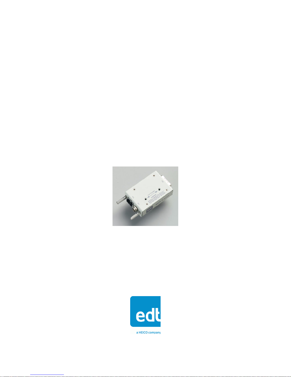
Figure 1 shows the RCX C-Link and its Camera Link connector:
MDR-26 Camera Link
connector
Figure 1. The RCX C-Link and Camera Link Connector
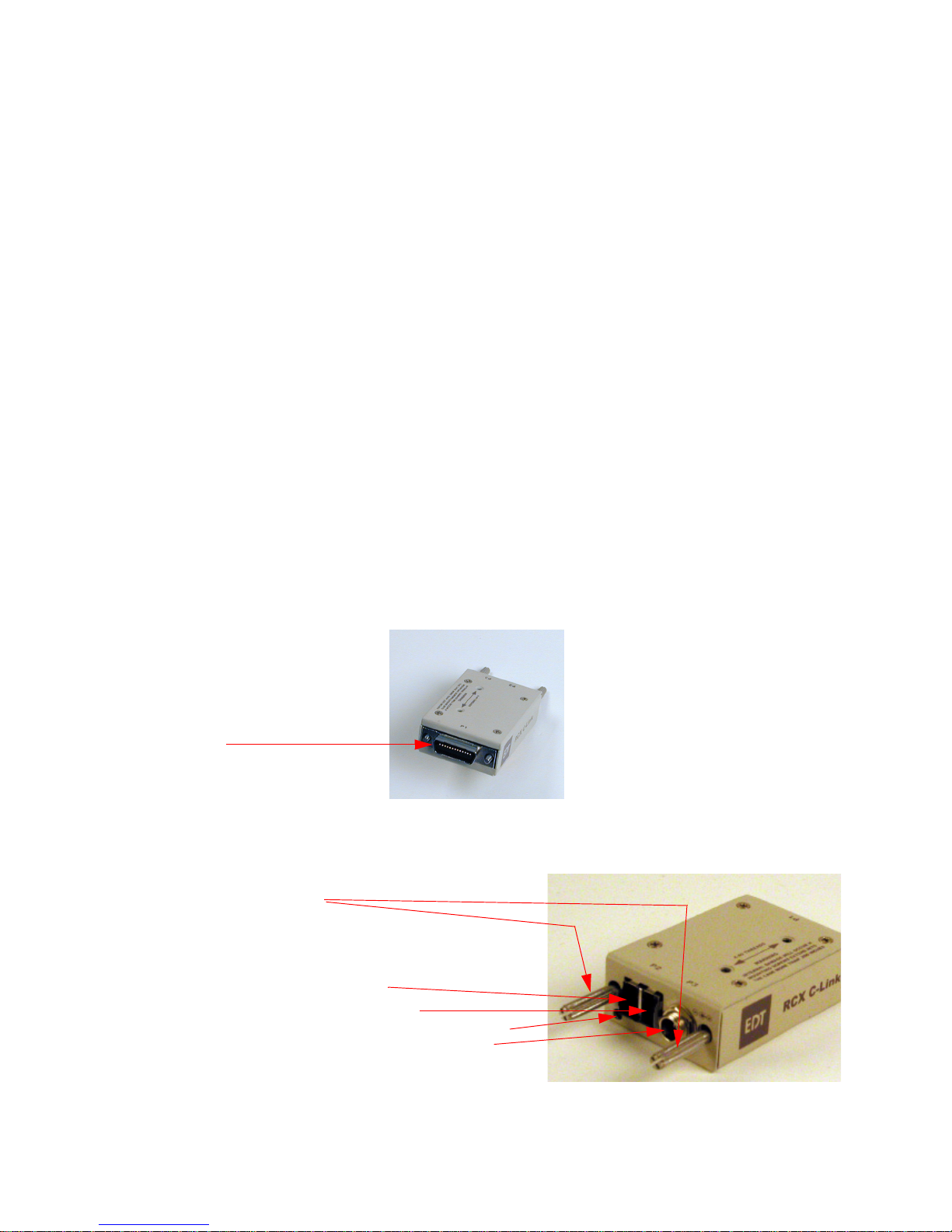
Figure 2 shows the RCX C-Link and its other connectors, and the LED status light:
thumb screws
LC duplex fiber optic connector
transmit
Figure 2. The RCX C-Link and Other Connectors
EDT, Inc. November 2006 1
receive
LED
power supply connector
Page 6

RCX C-Link User’s Guide Using the RCX C-Link in Base Mode
The RCX C-Link data sheet lists the product specifications.
Supported Cameras
The RCX C-Link supports base- and medium-mode Camera Link cameras when used with the
PCI DV FOX frame-grabber within the 200 MB per second bandwidth limitation of the PCI DV FOX
DMA engine. The RCX C-Link supports base-, medium-, and full-mode cameras from 20–80 MHz in
extension cord mode, using third-party frame-grabbers.
Medium- and full-mode extension cord operation requires the use of special versions of the RCX
C-Link.
RCX C-Link modules leave EDT configured for the operating mode specified when they were ordered.
Available operating modes are listed in Table 1 on page 9; instructions for reconfiguring the RCX
C-Link are in Setting the Blink Code on page 10.
References
The following related publication contains additional information on the EDT PCI digital video driver
and the PCI DV FOX frame grabber, including information on acquiring images:
Manual URL
PCI Digital Video User’s Guide www.edt.com/manuals/PDV/pcidv.pdf
Using the RCX C-Link in Base Mode
The RCX C-Link in base mode has one MDR-26 connector. Each pixel clock transfers 24 bits of video
data from the camera’s X channel. In addition, the RCX C-Link can also transfer four camera control
signals, and it has a bidirectional serial interface between frame-grabber and camera.
You can configure a system using the PCI DV FOX as a frame-grabber, or you can use two RCX
C-Link modules to form a fiber optic extension cord, with one module at the camera and the other at
the frame-grabber. Both uses are described below.
Using a Base-mode RCX C-Link With a PCI DV FOX
To configure the RCX C-Link for use with the PCI DV FOX frame-grabber:
1. Install the software driver as instructed in the PCI Digital Video User’s Guide.
2. Configure the RCX C-Link as described in the Setting the Blink Code on page 10.
3. Turn off power to the RCX C-Link, the camera, and the host computer.
4. Install the PCI DV FOX frame-grabber into a host PCI slot as described in the host computer doc-
umentation.
5. Connect the RCX C-Link directly to the MDR-26 connector on the back of the camera, as shown
in Figure 3.
EDT, Inc. November 2006 2
Page 7
Using the RCX C-Link in Base Mode RCX C-Link User’s Guide
Figure 3. Connecting the RCX C-Link to a Camera
6. Attach a fiber optic cable from the RCX C-Link to channel 0 of the PCI DV FOX — channel 0 is
the connector physically closest to the PCI bus.
7. Connect the power supply provided to the power connector on the back of the RCX C-Link.
8. Turn power back on to all devices.
9. Verify that the LED on the RCX C-Link and the Channel 0 LED on the PCI DV FOX show a solid
green light when power is applied to the camera and RCX C-Link. See LED Status on page 8 for
details.
Figure 4. Base-mode System With PCI DV FOX
3 EDT, Inc. November 2006
Page 8

RCX C-Link User’s Guide Using the RCX C-Link in Base Mode
Using a Base-mode RCX C-Link As an Extension Cord
You can use two RCX C-Link modules to form a fiber optic extension cord, with one module at the
camera and the other at the frame-grabber. In this case, the pixel clock rate into the frame-grabber
can be significantly higher than that presented by the camera, and the amount of time spent in blanking
will vary from line to line and frame to frame.
To use two RCX C-Link modules as an extension cord:
1. Install your Camera Link frame grabber and software as instructed by its manufacturer.
2. Configure both RCX C-Link modules as described in Setting the Blink Code on page 10. One RCX
C-Link is for the camera end, and the other is for the frame-grabber end.
3. Ensure that power is off to all devices.
4. Connect the RCX C-Link labeled Camera End to the MDR-26 connector on the back of the cam-
era.
5. Connect the RCX C-Link labeled For Frame Grabber to the MDR-26 connector on the back of
the frame-grabber.
6. Attach a fiber optic cable from one RCX C-Link to the other.
7. Connect the power supplies provided to the power connector on the back of each RCX C-Link
module.
8. Turn power back on to all devices.
9. Verify that both LEDs show a solid green light when power is applied to the camera and RCX
C-Links. See LED Status on page 8 for details.
Frame-grabber and camera operation is the same as when using a standard Camera Link cable.
EDT, Inc. November 2006 4
Page 9

Using the RCX C-Link in Medium and Full Modes RCX C-Link User’s Guide
Base-mode systems are configured as shown in Figure 4. Both 850 nm and 1310 nm systems are
configured in the same way; only the part numbers differ.
Figure 5. Base-mode Extension Cord System
Using the RCX C-Link in Medium and Full Modes
Medium- and full-mode Camera Link cameras have two MDR-26 connectors. The primary connector
operates in the same way as the base-mode interface; each pixel clock transfers 24 bits of video data
from the camera’s X channel. In addition, the primary connector can also transfer four camera control
signals, and it has a bidirectional serial interface between frame-grabber and camera.
The secondary connector transfers video data for the Y and Z channels:
• Medium-mode cameras transfer 24 bits of video data for the Y channel.
• Full-mode cameras transfer an additional 24 bits for the Z channel.
The standard full-mode configuration thus transports 72 bits of video data — 24 bits each for the X, Y,
and Z camera channels.
The X channel RCX C-Links at the camera and frame-grabber ends operate as a base-mode
extension cord, with one fiber to send video data from camera to frame-grabber, and another for
control signals from frame-grabber to camera. The YZ channel RCX C-Link at the camera end has two
fiber optic transmitters. Both fibers carry video data to the frame-grabber.
5 EDT, Inc. November 2006
Page 10

RCX C-Link User’s Guide Using the RCX C-Link in Medium and Full Modes
Many frame-grabbers require that video data presented at the primary and secondary connectors be
synchronized to within a fraction of a pixel clock. The Resync Cable described on page 18 provides a
common pixel clock to both RCX C-Links at the frame-grabber, and other synchronizing signals to
ensure that the starting pixel of each raster lines up across the X, Y and Z channels. The resync cable
also supplies power to the RCX C-Links.
NOTE To avoid damaging a component, ensure that the entire system is properly connected before
applying power to any of the components. In particular, do not apply power to the resync cable
while connecting or disconnecting it from the RCX C-Links.
Using a Medium-mode RCX C-Link With a PCI DV FOX
Full mode with the PCI DV FOX frame-grabber is of limited use due to the PCI DV FOX’s bandwidth
limit of 200 MB per second.
To connect your medium-mode system:
1. Install the software driver as instructed in the PCI Digital Video User’s Guide.
2. Configure the RCX C-Links as described in the Setting the Blink Code on page 10.
3. Turn off power to the RCX C-Links, the camera, and the host computer.
4. Plug the RCX C-Link labeled X Channel Camera into the camera’s primary MDR-26 connector.
5. Plug the RCX C-Link labeled Y Channel Camera into the camera’s secondary MDR-26 connec-
tor.
6. Connect the two power supplies with coaxial power connectors to the two camera-end RCX
C-Links.
7. Connect an LC duplex fiber from the X channel RCX C-Link at the camera end to channel 0 of the
PCI DV FOX — the connector physically closest to the PCI Bus.
8. Connect an LC duplex fiber from the YZ channel RCX C-Link at the camera end to channel 1 of
the PCI DV FOX — the connector physically farthest to the PCI Busd.
9. Verify that the LEDs on the RCX C-Links and the Channel 0 LED on the PCI DV FOX show a solid
green light when power is applied to the camera and RCX C-Links. See LED Status on page 8 for
details.
Using a Medium- or Full-mode RCX C-Link As an Extension Cord
Cameras operating in Camera Link medium or full modes require two RCX C-Link modules at each
end for data transfer. Each of the four RCX C-Link modules in a full-mode system is physically different
from the others. They are not interchangeable simply by changing blink codes.
To connect your system:
1. Install your Camera Link frame grabber and software as instructed by its manufacturer.
2. Configure the RCX C-Links as described in the Setting the Blink Code on page 10.
3. Turn off power to the RCX C-Links, the camera, and the host computer.
4. Plug the RCX C-Link labeled X Channel Camera into the camera's primary MDR-26 connector.
5. Plug the RCX C-Link labeled YZ Channel Camera into the camera's secondary MDR-26 connec-
tor.
6. Plug the RCX C-Link labeled X Channel FG into the frame-grabber's primary MDR-26 connector.
EDT, Inc. November 2006 6
Page 11

Using the RCX C-Link in Medium and Full Modes RCX C-Link User’s Guide
7. Plug the RCX C-Link labeled YZ Channel FG into the frame-grabber’s secondary MDR-26 con-
nector.
8. Connect the two power supplies with coaxial power connectors to the two camera-end RCX
C-Links.
9. Connect the resync cable with two Lemo connectors to each of the two RCX C-Links at the frame-
grabber end. The resync cable’s two Lemo connctors are interchangeable.
10. Connect the power supply with the 9-pin D-shell connector to the resync cable connector.
11. Connect an LC duplex fiber from the X channel RCX C-Link at the camera end to the X channel
RCX C-Link at the frame-grabber end.
12. Connect an LC duplex fiber from the YZ channel RCX C-Link at the camera end to the YZ channel
RCX C-Link at the frame-grabber end.
13. g3g3Verify that all four LEDs show a solid green light when power is applied to the camera and
RCX C-Links. See LED Status on page 8 for details.
Full-mode extension cords systems are configured as shown in Figure 6. Both 850 nm and 1310 nm
systems are configured in the same way; only the part numbers differ.
Figure 6. Full-mode Extension-cord System
Eighty-bit Packing
Certain full mode cameras, such as the Basler A04k and Mikrotron MC1310 and MC1311, reassign
the Spare, Data-valid, and Frame-valid control signals to allow the transport of up to 80 bits of data
per pixel clock. The RCX C-Link can be configured with a blink code to accommodate these cameras.
Blink codes of 1-5 (at the camera end) and 2-5 (at the frame-grabber end) allow 80-bit packing at
frequencies of 60–72 MHz. The 72 MHz upper limit is determined by the bandwidth available over the
fiber, but is sufficient to support all modes currently available on the cameras specified above.
7 EDT, Inc. November 2006
Page 12

RCX C-Link User’s Guide LED Status
LED Status
• When first powered on, the LED displays the current blink code, then blinks erratically for a few
seconds while the firmware is loading.
• In normal operation, a solid green light indicates the RCX C-Link is working properly.
• Slow blinking indicates the RCX C-Link is not receiving a correct fiber optic signal.
• Rapid blinking indicates the RCX C-Link is not locked into the camera clock.
• If the RCX C-Link displays a combination of slow and rapid blinks, both errors are present.
NOTE When used as an extension cord, the RCX C-Link on the frame-grabber end generates its own
camera clock; therefore, a rapid blink indicates a hardware fault in the RCX C-Link, or, in a full- or
medium-mode system, possibly the resync cable.
A slow blink indicates a problem with the fiber optic connection from the remote device to the device
with the slowly blinking LED. Common causes are:
• no power at the transmitting end;
• blink codes with incompatible link rates (see Table 1);
• a broken fiber or an incorrect fiber type; or
• dust or dirt in the fiber optic transceivers (see Fiber Optic Transceivers on page 15).
Configuration
The standard firmware for the RCX C-Link supports most Camera Link base-mode cameras from 20
to 80 MHz, UART data rates of up to 19.2 KBaud. (Higher baud rates are possible.) By setting the
operating mode using the LED’s blink code, you can configure the RCX C-Link to support many
different kinds of cameras for use with a PCI DV-FOX fiber-optic frame-grabber, or for use at either
end of an extension cord.
Each RCX C-Link leaves EDT configured with the appropriate blink code to support its required
operation. For a typical base-mode system,a blink code of 1-1 at the camera end and 2-1 at the framegrabber end permits standard base-mode operation at clock frequencies of 20–40 MHz. For a typical
full mode system, a blink code of 1-4 on both RCX C-Links at the camera end, and of 2-4 on both at
the frame-grabber end, permits standard full-mode operation at clock frequencies of 60–80 MHz.
Each RCX C-Link leaves EDT labeled with that blink code with which it has been configured. On such
labels for medium- or full-mode systems, X Channel refers to the primary MDR-26 connnector on the
camera or frame-grabber, and YZ Channel to the secondary.
Operating Modes and Blink Codes
The RCX C-Link can transfer camera data at various speeds, depending on the operating mode
chosen. You select an operating mode by setting a pattern of blinks — the blink code — for the
module’s LED.
A blink code consists of two digits: for those blink codes that begin with 1 or 2, the first indicates
whether the module is at the camera end (a blink code first digit of 1) or the frame-grabber end (a blink
code first digit of 2). The second digit of the blink code must be the same for both camera and framegrabber ends.
EDT, Inc. November 2006 8
Page 13

Configuration RCX C-Link User’s Guide
If you’re using the RCX C-Link with a PCI DV FOX fiber optic frame-grabber, you need to set a blink
code at the camera end only.
Blink Codes for Base-mode Systems
An RCX C-Link module running firmware revision 11 or higher with base-mode cameras offers the
operating modes shown in Table 1.
Table 1. Base-mode Blink Codes and Operating Modes
Camera
Blink Code End
1-1 camera 20–40 MHz 24 bits 1.25 GBaud
1-2 camera 20–60 MHz 16 bits 1.25 GBaud
1-3 camera 20–60 MHz 24 bits 2.5 GBaud
1-4 camera 60–80 MHz 24 bits 2.5 GBaud
2-1 frame-grabber 40 MHz 24 bits 1.25 GBaud
2-2 frame-grabber 60 MHz 16 bits 1.25 GBaud
2-3 frame-grabber 60 MHz 24 bits 2.5 GBaud
2-4 frame-grabber 80 MHz 24 bits 2.5 GBaud
3-3 firmware update ( See Updating the Firmware on page 12.) 1.25 GBaud
2 fast, 2 slow, 2 fast Error: unsupported code entered
For additional LED blinking behavior, see LED Status on page 8.
Clock Rate
Constraints Link Rate
Most base-mode Camera Link cameras operate between 20 and 40 MHz, so use blink codes of 1-1
at the camera end and 2-1 at the frame-grabber end.
Blink code 2-1 at the frame-grabber end of an extension cord regenerates a constant 40 MHz pixel
clock to the frame-grabber asynchronous to the camera’s actual clock; this is also suitable for cameras
operating between 20 and 40 MHz. Data for an entire raster is accumulated, then sent to the framegrabber in one burst. The regenerated clock at the frame-grabber end must be at least as fast as the
camera clock at the camera link interface; for each frame-grabber blink code, this regenerated clock
rate is given in the Camera Clock Rate column.
If the raster is very long and if the regenerated frame-grabber end clock is much faster than that of the
camera, the frame-grabber end RCX C-Link may have to drop Data-Valid mid-raster and wait for
additional data from the camera. This seldom occurs, and most frame-grabbers can handle it and
continue normal operation.
Cameras operating between 40 and 60 MHz are usually best served by blink codes 1-3 and 2-3. If the
camera needs only 16 data bits or fewer transferred per clock cycle (instead of all 24), it is possible to
use blink codes 1-2 and 2-2 instead, and thus operate the link at 1.25 GBaud for longer range and
lower power dissipation. The selection of 16-bit mode is made only at the frame-grabber end through
blink code 2-2, or through the mode16: 1 directive in a PCI DV FOX configuration file; this information
is communicated over the fiber to the RCX C-Link at the camera end. (At the camera end, blink codes
1-1 and 1-2 are identical.)
At reset (and whenever the RCX C-Link cannot lock to the camera clock), the RCX C-Link initializes
to assume that the Camera Link Data-Valid signal is never asserted, and ignores it. Many Pulnix
cameras do not assert Data-Valid, so this behavior is useful for those using such cameras. The first
occurrence of Data-Valid true from the camera causes the RCX C-Link to use Data-Valid to qualify
video data from that point on.
9 EDT, Inc. November 2006
Page 14

RCX C-Link User’s Guide Configuration
In the case of a dual tap camera, the Camera Link pixel clock is half the camera’s pixel rate. For
example, a dual-tap 12-bit camera with a 40 MHz Camera Link clock sends 80 million pixels per
second. This camera is compatible with the RCX C-Link in blink code 1-1.
Blink Codes for Medium- and Full-mode Systems
An RCX C-Link module running firmware revision 11 or higher with medium- and full-mode cameras
offers the operating modes shown in Table 2.
Table 2. Medium- and Full-mode Blink Codes and Operating Modes
Camera
Blink Code End
1-1 camera 20–40 MHz 72 bits 1.25 GBaud
1-2 undefined
1-3 camera 20–60 MHz 72 bits 2.5 GBaud
1-4 camera 60–80 MHz 72 bits 2.5 GBaud
1-5 camera 60–72 MHz for 80-bit full-mode cameras 2.5 GBaud
2-1 frame-grabber 20–40 MHz* 72 bits 1.25 GBaud
2-2 undefined
2-3 frame-grabber 20–60 MHz* 72 bits 2.5 GBaud
2-4 frame-grabber 60–80 MHz* 72 bits 2.5 GBaud
2-5 frame-grabber 60–72 MHz* for 80-bit full-mode cameras 2.5 GBaud
3-3 firmware update ( See Updating the Firmware on page 12.) 1.25 GBaud
2 fast, 2 slow, 2 fast Error: unsupported code entered
*The resync cable determines the actual frequency.
For additional LED blinking behavior, see LED Status on page 8.
Clock Rate
Constraints Link Rate
Most full-mode Camera Link cameras operate between 60 and 80 MHz, so use blink codes of 1-4 at
the camera end and 2-4 at the frame-grabber end. Full-mode cameras that transfer 80 bits per clock
cycle can use blink codes 1-5 (camera end) and 2-5 (frame-grabber end).
Many medium-mode Camera Link cameras operate at 40 MHz, so use blink codes of 1-1 at the
camera end and 2-1 at the frame-grabber end.
See Firmware on page 12 for instructions on verifying and updating the firmware.
Setting the Blink Code
You select the operating mode of an RCX C-Link by setting the appropriate blink code, if necessary.
(RCX C-Link modules leave EDT configured with the blink code that’s correct for the operating mode
specified when they were ordered.)
To set the blink code:
1. Turn off power to the RCX C-Link module. Only a power supply need be connected to it, nothing
else. It may be helpful, however, to connect the power supplyto a power strip, or otherwise arrange
matters so that you can easily turn the power back on while accessing the recessed button.
2. Press the recessed button on the RCX C-Link with a blunt object such as a ballpoint pen (see pic-
ture below).
EDT, Inc. November 2006 10
Page 15

Configuration RCX C-Link User’s Guide
3. Still keeping the button pressed, turn the power back on, perhaps using the switch on a power
strip. The green LED turns on, then turns off when the button is released.
NOTE If pressed longer than two seconds, the LED blinks a series of diagnostic blinks. If this occurs, turn
the power off again and then restart the procedure.
Figure 7. Setting the Operating Mode
4. Press and hold the button. The LED blinks slowly.
5. Release the button after the LED has blinked the correct number of times for the first digit of the
required blink code, as specified in Table 1. For example, if you want to set the mode to 2-3, wait
for the LED to blink twice before releasing the button.
6. Press the button again and release it after the LED has blinked the correct number of times for the
second digit of the required blink code. For example, if you want to set the mode to 2-3, wait for
the LED to blink three times before releasing the button.
The RCX C-Link saves your selection into flash memory immediately after you enter the second
digit of the code. The LED now blinks in the pattern selected.
NOTE If the LED blinks the error blink code of two fast, two slow, and two fast, an error has occurred and
the code has not been saved to memory.
7. Cycle power to the module without pressing the button.
When the RCX C-Link is powered up without the button pressed, the LED flashes the current code
once, then show its status (see
Using the RCX C-Link in Base Mode on page 2).
NOTE If you enter an unsupported code, the LED blinks two short blinks, two long blinks, then two short
blinks.
Backward Compatibility
Most RCX C-Links with firmware revisions earilier than revision 11 support only cameras with speeds
of 20–40 MHz at 1.25 GBaud using blink codes 1-1 (ignore Data-Valid), 1-2 (use Data-Valid), and 2-1
(frame-grabber end). (Some were shipped with special firmware to support other types of cameras.)
For backward compatibility, firmware of revision 11 or later, as described in Table 1, behaves
identically for blink codes 1-1 and 1-2. As of revision 11, Data-Valid is automatically detected.
Also, customers using blink code 2-2 at the frame-grabber end for 16-bit mode can use the
corresponding blink code of 1-2 at the camera end.
If blink code 3-5 (not shown in Table 1) does not produce the error blink for an unsupported blink code
(two fast, two slow, two fast), then you have firmware of revision 11 or later.
11 EDT, Inc. November 2006
Page 16

RCX C-Link User’s Guide Firmware
Firmware
RCX C-Links for base, medium, and full modes as of November 2006 are shipped configured with
these firmware files:
Table 3. FPGA Configuration Files for the
RCX C-Link mode / channel FPGA configuration file
base mode rgb11.rcx
medium mode, X channel mx11.rcx
medium mode, YZ channel my11.rcx
full mode, X channel fx11.rcx
full mode, YZ channel fyz11.rcx
If you are using the RCX C-Link with a PCI DV FOX, you can use the rcxload utility to verify or
update the firmware on an RCX C-Link module.
NOTE Without a PCI DV FOX, the rcxload utility is not available. For updated firmware, ship the
module back to EDT.
Contact EDT before updating the firmware on a full-mode system.
RCX C-Link
Verifying the Firmware
Before you update the firmware, you may wish to verify that it’s necessary.You can use the rcxload
utility to verify that the firmware loaded into the module is the same as that in a specified firmware file.
To do so, enter:
rcxload -v file.rcx
substituting the name of a valid RCX C-Link firmware file for file.rcx..
The utility compares the firmware in the RCX C-Link module bit by bit with the firmware in the specified
firmware file. If they are the same, it reports verified and 0 errors; if not, it reports not
verified and lists the errors.
NOTE Avoid updating the firmware unless it’s necessary. If your RCX C-Link module is working correctly,
there’s ordinarily no need to update its firmware.
Updating the Firmware
The instructions below allow you to update the firmware in an RCX C-Link module to the current
firmware revision. However, do so only after reading the information below:
NOTE Field updates of full-mode YZ channel units are not currently possible. Contact EDT to update the
firmware on a full-mode system.
CAUTION
To avoid corrupting the firmware on the RCX C-Link, do not interrupt the update by pressing
Ctrl-C or turning off the power while the update is in progress.
EDT, Inc. November 2006 12
Page 17

Firmware RCX C-Link User’s Guide
To update the RCX C-Link firmware to the current revision:
1. Run pciload with no arguments to ensure that the system recognizes the PCI DV FOX. Typical
output appears thus:
pdv unit 0 (pci dv fox):
XC2S200 PCI FPGA, AMD 29LV081B 8MB FPROM
s/n AP0064, p/n 019-02103-11, i/f fpga xc2s400e, rev 11 clock 40 Mhz, opt f2
Sector 0
Sector 1
Sector 2 PROM id: <dvtlk4_3v.ncd 2s200fg456 2005/06/10 14:58:10>
Sector 3 PROM id: <dvtlk4_5v.ncd 2s200fg456 2005/06/10 14:58:16>
2. Put the RCX C-Link into blink code 3-3. (See Setting the Blink Code on page 10 for instructions.)
3. Power-cycle the RCX C-Link.
4. Make sure the fiber optic cable is connected to channel 0 of the PCI DV FOX — the channel phys-
ically closest to the PCI bus. The RCX C-Link need not be connected to a camera.
5. Query the RCX C-Link to make sure it’s there and recognized, by entering rcxload with no ar-
guments. After you’ve started rcxload, the LEDs on both devices are lighted and not blinking.
Typical output appears thus:
pdv unit 0 (pci dv fox) chan. 0 RCX module:
sector 0 [10000]: <rgb11cm60_a01.ncd 2vp2fg256 2006/03/30 20:05:34>
sector 1 [38000]: <rgb11cm80_a01.ncd 2vp2fg256 2006/03/30 20:12:36>
sector 2 [60000]: <rgb11fg40_a01.ncd 2vp2fg256 2006/03/30 19:57:41>
sector 3 [88000]: <rgb11fg60_a01.ncd 2vp2fg256 2006/03/30 20:02:08>
sector 4 [b0000]: <rgb11fg80_a01.ncd 2vp2fg256 2006/03/30 20:09:30>
sector 5 [d8000]: <fud02b.ncd 2vp2fg256 2006/03/28 15:59:19>
If your output appears faulty, check the blink code, cables, and connections. If you still have
problems, e-mail the output to tech@edt.com.
6. Assuming correct output from step 5 above, update the firmware by running:
rcxload -u 0 flash/rcx/file.rcx
replacing file.rcx with the filename of the current firmware revision.
The filename must be a valid .rcx file. EDT software packages ship with the current .rcx files in the
flash
/rcx subdirectory. The README file in the package has information about any .rcx file
updates including the specific filename of the current revision.
After a successful update, switch the module to the appropriate operating mode for its intended use.
For instructions, see Configuration on page 8.
NOTE If
rcxload reports errors within a section flagged as “critical,” do not power-cycle the RCX C-Link.
Instead, repeat the procedure. If you still get errors, leave the RCX C-Link powered on and contact
EDT.
You can turn off power to the host computer and camera. The RCX C-Link can be left powered on
indefinitely.
13 EDT, Inc. November 2006
Page 18

RCX C-Link User’s Guide Pinouts
Pinouts
Table 4 shows the MDR-26 connector pin assignments for base-, medium-, and full-mode systems.
Table 4. MDR-26 Pin Assignments
Camera end Frame-grabber
end
1 1 inner shield inner shield inner shield
14 14 inner shield inner shield inner shield
2 25 X0– Y0– Y0–
15 12 X0+ Y0+ Y0+
3 24 X1– Y1– Y1–
16 11 X1+ Y1+ Y1+
4 23 X2– Y2– Y2–
17 10 X2+ Y2+ Y2+
5 22 Xclk– Yclk– Yclk–
18 9 Xclk+ Yclk+ Yclk+
6 21 X3– Y3– Y3–
19 8 X3+ Y3+ Y3+
7 20 SerTC+ unused 100 ohms
20 7 SerTC– unused terminated
8 19 SerTFG– unused Z0–
21 6 SerTFG+ unused Z0+
9 18 CC1– unused Z1–
22 5 CC1+ unused Z1+
10 17 CC2+ unused Z2–
23 4 CC2– unused Z2+
11 16 CC3– unused Zclk–
24 3 CC3+ unused Zclk+
12 15 CC4+ unused Z3–
25 2 CC4– unused Z3+
13 13 inner shield inner shield inner shield
26 26 inner shield inner shield inner shield
Camera Link signal
base mode
(primary connector)
Camera Link signal
medium mode
(secondary connector)
Camera Link signal
full mode
(secondary connector)
Options
Your RCX C-Link can be customized in various ways. Some of these options can be ordered from
EDT; others are available from third-party vendors.
NOTE The final two digits of EDT part numbers indicate the revision level; specify a final
the most recent revision of a product.
• Custom transceivers (extended range of 5 km or more, 1310 nm, CWDM, single-fiber PON).
• DualTX and DualRX RCX C-Link versions for use on the secondary port of full-mode cameras.
EDT, Inc. November 2006 14
-xx to obtain
Page 19

Options RCX C-Link User’s Guide
• A 7-pin Lemo connector instead of our standard coaxial power connector, allowing:
— a Lemo connector to DB-9 with RS-232 drivers for an extra UART port across the fiber, or
— local triggering directly into the camera, using a DB-9 to Lemo cable.
• Resync cable for use at frame-grabber end of medium- and full-mode extension cords.
• A two-foot Camera Link extender cable is available. Contact EDT for a quote on EDT part number
016-02563-00. Other lengths are possible from 3M Corp; their website lists this as a 3M™ Mini D
Ribbon (MDR) Cable Assembly, .050". Search for part numbers that include the string TZLB, and
choose a result that refers to 1W226-TZLB-XXX-0LC.
If the RCX C-Link is attached to a cable rather than the camera, you might need to secure it as
needed using the mounting holes on the RCX C-Link module case.
NOTE The mounting nuts in the top of theRCX C-Link case use 4-40 threads. To avoid damaging the
RCX C-Link, mounting screws must not extend more than 0.2 inch into the case.
Fiber Optic Transceivers
Our standard RCX C-Link currently uses the 850 nm Stratos Lightwave SLC-25-C-1-E fiber optic
transceiver. An extended-range option uses the 1310 nm Finisar FTRJ11319F1GTL. Transceivers
from other vendors may be substituted without notice.
CAUTION
Though the transceivers we use conform to regulated limits, to avoid damaging your eyesight,
never look directly into a fiber optic transceiver of any kind.
These transceivers can be used with different kinds of optical fiber, as shown in Table 5:
Table 5. Transceiver and Fiber Combinations
Thickness
(microns)
62.5 multimode 850 nm 300 150
50 multimode 850 nm 500 250
9 single-mode 1310 nm 10,000 5000
Fiber Type Wavelength Maximum length (meters)
at 1.25 GBaud at 2.5 GBaud
Other types of transceivers are also available as options:
Single fiber transceivers
These have an integrated passive optical multiplexer and transmit data in each
direction over one fiber using different colors of light. This is especially useful when
going through an optical rotary joint. Some operate at distances up to 60 Km.
CWDM transceivers
These use up to 16 different colors of light, split and combined by passive optical
multiplexers external to the RCX C-Link. With these, it’s possible to operate a
dozen different cameras simultaneously over a single fiber.
DualTX and DualRX transceivers
These are used in our full-mode solutions, as the secondary camera link connector
must carry twice as much data as the primary connector.
15 EDT, Inc. November 2006
Page 20

RCX C-Link User’s Guide Options
Transceiver Care
Dust in the connectors can cause problems with transceivers. If you suspect such a problem:
1. Direct a blast of compressed air away from any electronic components to blow out any water that
may have condensed in the air nozzle.
2. Blow a blast of compressed air directly into the transceiver ports to dislodge any dust particles that
may have collected in them.
NOTE It is critical to keep the transceivers clean and dust-free.
Lemo Connector Option
Our standard power connector is a coaxial Switchcraft that locks into place through a threaded sleeve.
We can substitute a 7-pin Lemo connector, EDT part number 016-02445-01, as an option to make the
RCX C-Link more versatile. With the Lemo connector, you can use either of two cables that allow
auxiliary signals.
(On medium- and full-mode extension cord systems, the RCX C-Links at the frame-grabber ends use
the Lemo connectors for the resync cable.)
When looking into the Lemo connector on the end of the RCX C-Link module, you see the pins laid
out as shown in Figure 8, using Lemo pin numbering. Pin 2 is always power to the RCX C-Link, +4.75
to +18 V DC. Pin 7 is always ground (for both signals and power). The other five pins are defined by
the firmware installed on the RCX C-Link. These pins are normally used at CMOS +3.3 V signal levels,
though the RCX C-Link can be configured with minor hardware modifications to use pins 1,6 and 3,4
as LVDS signal pairs.
==
1 6
2 7 5
3 4
key in the connector barrel at the top
Figure 8. Lemo Pin Layout
Lemo to Male DB-9 Cable (Base-mode Cameras Only)
EDT offers an optional Lemo to DB-9 cable (part number 016-02718-00) for use with the above Lemo
connector. This cable provides signals that can be used as an auxiliary signaling system for a variety
of purposes; it also supplies power to the RCX C-Link.
Custom firmware could allow the auxiliary signals to be used, for example, to control the camera’s pan
and servo motors. It’s also possible to set up a hardware trigger local to either end. Contact EDT if you
wish to explore these options.
Unlike the Lemo to Female DB-9 RS-232 Cable (Base-mode Cameras Only) discussed below, the DB9 connector in this cable has no integrated level conversion, nor looped back signals.
Table 6 shows the color coding for the Lemo to DB-9 power cable, and how the standard firmware
uses each wire:
EDT, Inc. November 2006 16
Page 21

Options RCX C-Link User’s Guide
Table 6. Lemo to Male DB-9 Cable Pinout
Lemo Pin
Number Color
1 green 2 AUX_TX, primary auxiliary transmit UART CMOS +3.3 V
2 red 9 power to RCX C-Link 4.75 – 18 V
3 orange 7 AUX2_TX, secondary auxiliary transmit CMOS +3.3 V
4 brown 8 AUX2_RX, secondary auxiliary receive CMOS +3.3 V
5 white 4 SYNC, can be configured as an outgoing copy of the
6 blue 3 AUX_RX, primary auxiliary receive UART CMOS +3.3 V
7 black 5 ground ground
DB-9 Pin
Number Standard Firmware (rgb11.rcx) Signal Level
CMOS +3.3 V
camera’s Frame-valid signal
All five CMOS 3.3 V signals go to FPGA 3.3 V I/O pins using series 100-ohm resistors. Custom
firmware can configure these pins as input or output.
NOTE DB-9 pins 1 and 6 are spare.
Lemo to Female DB-9 RS-232 Cable (Base-mode Cameras Only)
EDT offers an optional Lemo to DB-9 RS-232 cable (part number 016-02445-01), with integrated
CMOS +3.3 V to RS-232 level converters on a small circuit board inside the DB-9 connector shell. This
cable is designed to plug in directly to a host computer serial port.
It offers an auxilliary UART connection over the fiber, in addition to the UART normally associated with
the Camera Link standard. This auxilliary UART can be used, for example, to control the camera’s pan
and zoom servo motors from the host at 19.2 KBaud or less. Alternatively, they can be used for other
low bandwidth signals.
Unlike the Lemo to Male DB-9 Cable (Base-mode Cameras Only) discussed above, the DB-9
connector does not supply power to the RCX C-Link. Instead, a red wire (power) and a black wire
(ground), both 24 inches long, are left loose for you to hook up your own power source. The required
power is +4.75 to 18 V DC.
Table 7 shows the color coding for the Lemo to DB-9 RS-232 cable, and how the standard firmware
(in
rgb11.rcx) uses each wire. DB-9 pins 1, 4, and 6 are wired together and unconnected; 7 and 8
are also wired together, and 9 is also unconnected — these signals are not otherwise used.
Table 7. Lemo to Female DB-9 RS-232 Cable Pinout
Lemo End DB-9 End
Pin Purpose Signal Level Pin Purpose Signal Level
1 UART_TX, auxiliary transmit
UART from RCX C-Link
2 power red wire out
3 reserved
4 reserved
5 reserved
6 UART_RX, auxiliary receive
UART from
7 ground 5 black wire out
RCX C-Link
CMOS +3.3 V 2 data transmit RS-232
CMOS +3.3 V 3 data receive RS-232
17 EDT, Inc. November 2006
Page 22

RCX C-Link User’s Guide Options
Resync Cable
When used for medium- and full-mode extension cords, two RCX C-Links are needed at the framegrabber end. The EDT resync cable sends a common clock signal from an oscillator inside the DB-9
shell to each of the two RCX C-Links at the frame-grabber end. This cable also allows the X Channel
RCX C-Link to signal the YZ channel RCX C-Link when to start each raster.
The two Lemo connectors on the resync cable are interchangeable.
The resync cable must have an oscillator frequency greater than or equal to the camera pixel clock
rate. The pixel clock re-created for the frame-grabber is asynchronous to that generated by the
camera; thus, the amount of time spent in horizontal blanking varies from one raster line to the next.
If the camera's clock rate is slower than that of the resync cable, a greater percentage of time will be
spent in horizontal blanking at the frame-grabber.
Three resync cables are available, offering 40, 60, and 80 MHz clock rates:
Clock Rate EDT Part Number
40 MHz 016-02673-00
66.666 MHz 016-02675-00
80 MHz 016-02613-00
Choose a blink code from Table 1 whose frequency range includes the frequency generated by the
cable assembly.
Table 8 shows the signal assignments:
Table 8. Resync Cable Pinout With Male DB-9
Lemo
Pin
Lemo Signal DB-9 Signal DB-9
Pin
1 START_RASTER+, LVDS signal from X to YZ RCX C-Link — unconnected —
2 power power 9
3
CLOCK+, LVDS pixel clock into X and YZ RCX C-Links
4 CLOCK-, LVDS pixel clock into X and YZ RCX C-Links — unconnected —
5 reserved — unconnected —
6 START_RASTER-, LVDS signal from X to YZ RCX C-Link — unconnected —
7 ground ground 5
— unconnected —
If you’re using the resync cable, you will also need a power source, such as the International Power
Supply With DB-9 Connector described on page 19.
EDT, Inc. November 2006 18
Page 23

Power Supply RCX C-Link User’s Guide
Power Supply
The RCX C-Link at the camera end of a base-mode system has the following power requirements:
Table 9. U.S. Power Supply
Voltage in 100–240 V, 50–60 Hz from AC mains
Voltage out 5 V DC, 1 A
Power supply connector Switchcraft 760K
The 5 V power supply is small and comes with a U.S.-standard power plug.
Table 10. International Power Supply
Voltage in 100–240 V, 50–60 Hz from AC mains
Voltage out 12 V DC, 0.84 A
Power supply connector Switchcraft 760K
The 12 V power supply includes four international power plug adaptors.
Table 11. International Power Supply With DB-9 Connector
Voltage in 100–240 V, 50–60 Hz from AC mains
Voltage out 12 V DC, 0.84 A
Power supply connector DB-9 female
Power required on a full mode system has been measured at under 6 watts for each end — camera
and frame-grabber. This power is spread across two RCX C-Links: typically, two watts for the X
channel RCX C-Link, and 3.5 watts for the YZ channel RCX C-Link. A switching regulator inside the
RCX C-Link allows us to accept anything from 4.75–18 volts DC; however, lower voltages are
recommended to avoid running hot.
The two RCX C-Links at the camera end of a full-mode system can use either of the two power
supplies with the Switchcraft connectors. The two RCX C-Links at the frame-grabber end of a fullmode system receive power from our resync cable through a female DB-9 connector. The resync
cable connects to the RCX C-Links through two Lemo 7-pin connectors.
Dimensions
The RCX C-Link box has the dimensions shown in Figure 9.
NOTE With respect to the dimensions shown in Figure 9:
Connector dimensions are approximate — refer to manufacturer’s specifications for precise
dimensions.
The power connector dimension of 0.31 inch is for the standard 2-conductor connector; the
optional Lemo connector is approximately 0.35 inch.
19 EDT, Inc. November 2006
Page 24

RCX C-Link User’s Guide Dimensions
Figure 9. RCX C-Link Dimensions
Figure 10 shows the cable clearance. Cable clearance for optical fiber can vary, depending on the fiber
used; the value shown is typical.
Figure 10. Cable Clearance
EDT, Inc. November 2006 20
 Loading...