

Page 1
User’s Guide
Camera Link PCI Express
(PCIe) Gen1 Framegrabbers
High-speed image capture for
Camera Link on PCIe platforms
Doc. 008-04053-00
Rev. 2012 March 16
Page 2

Engineering Design Team (EDT), Inc.
1400 NW Compton Drive, Suite 315
Beaverton, OR 97006
p 503-690-1234 / 800-435-4320
f 503-690-1243
www.edt.com
TM
EDT
and Engineering Design TeamTM are trademarks of Engineering Design Team, Inc. All other trademarks, service marks,
and copyrights are the property of their respective owners
†
.
© 1997-2012 Engineering Design Team, Inc. All rights reserved.
FCC Compliance: EDT devices described herein are in compliance with part 15 of the FCC Rules. Operation is subject to two
conditions: (1) The device may not cause harmful interference, and (2) the device must accept any interference received,
including interference that may cause undesired operation.
This equipment has been tested and found to comply with the limits for a Class A digital device, pursuant to part 15 of FCC Rules.
These limits are designed to provide reasonable protection against harmful interference in a commercial environment. This
equipment generates, uses, and can radiate radio frequency energy and, if not installed and used as described in the user’s
guide, may cause harmful interference to radio communications. Operating this equipment in a residential area is likely to cause
harmful interference, in which case the user will be required to correct the interference at his or her own expense.
Caution: Changes or modifications not expressly approved by Engineering Design Team, Inc. could void your warranty to
operate this equipment.
EDT, Inc. ii
Page 3

Terms of Use Agreement
Definitions. This agreement, between Engineering Design Team, Inc. (“Seller”) and the user or distributor (“Buyer”), covers the
use and distribution of the following items provided by Seller: a) the binary and all provided source code fo r any and all device
drivers, software libraries, utilities, and example applications (collectively, “Software”); b) the binary and all provided source code
for any and all configurable or programmable devices (collectively, “Firmware”); and c) the computer boards and all other physical
components (collectively, “Hardware”). Software, Firmware, and Hardware are collectively referred to as “Products.” This
agreement also covers Seller’s published Limited Warranty (“Warranty”) and all other published manuals and product information
in physical, electronic, or any other form (“Documentation”).
License. Seller grants Buyer the right to use or distribute Seller’s Software and Firmware Products solely to enable Seller’s
Hardware Products. Seller’s Software and Firmware must be used on the same computer as Seller’s Hardware. Seller’s Products
and Documentation are furnished under, and may be used only in accordance with, the terms of this agreement. By using or
distributing Seller’s Products and Documentation, Buyer agrees to the terms of this agreement, as well as any additional
agreements (such as a nondisclosure agreement) between Buyer and Seller.
Export Restrictions. Buyer will not permit Seller’s Software, Firmware, or Hardware to be sent to, or used in, any other country
except in compliance with applicable U.S. laws and regulations. For clarification or advice on such laws and regulations, Buyer
should contact: U.S. Department of Commerce, Export Division, Washington, D.C., 20230, U.S.A.
Limitation of Rights. Seller grants Buyer a royalty-free right to modify, reproduce, and distribute executable files using the
Seller’s Software and Firmware, provided that: a) the source code and executable files will be used only with Seller’s Hardware;
b) Buyer agrees to indemnify, hold harmless, and defend Seller from and against any claims or lawsuits, including attorneys’ fees,
that arise or result from the use or distribution of Buyer’s products containing Seller’s Products. Seller’s Hardware may not be
copied or recreated in any form or by any means without Seller’s express written consent.
No Liability for Consequential Damages. In no event will Seller, its directors, officers, employees, or agents be liable to Buyer
for any consequential, incidental, or indirect damages (including damages for business interruptions, loss of business profits or
information, and the like) arising out of the use or inability to use the Products, even if Seller has been advised of the possibility
of such damages. Because some jurisdictions do not allow the exclusion or limitation of liability for consequential or incidental
damages, the above limitations may not apply to Buyer. Seller’s liability to Buyer for actual damages for any cause whatsoever,
and regardless of the form of the action (whether in contract, product liability, tort including negligence, or otherwise) will be
limited to fifty U.S. dollars ($50.00).
Limited Hardware Warranty. Seller warrants that the Hardware it manufactures and sells shall be free of defects in materials
and workmanship for a period of 12 months from date of shipment to initial Buyer. This warranty does not apply to any product
that is misused, abused, repaired, or otherwise modified by Buyer or others. Seller’s sole obligation for breach of this warranty
shall be to repair or replace (F.O.B. Seller’s plant, Beaverton, Oregon, USA) any goods that are found to be non-conforming or
defective as specified by Buyer within 30 days of discovery of any defect. Buyer shall bear all installation and transportation
expenses, and all other incidental expenses and damages.
Limitation of Liability. In no event shall Seller be liable for any type of special consequential, incidental, or penal damages,
whether such damages arise from, or are a result of, breach of contract, warranty, tort (including negligence), strict liability, or
otherwise. All references to damages herein shall include, but not be limited to: loss of profit or revenue; loss of use of the goods
or associated equipment; costs of substitute goods, equipment, or facilities; downtime costs; or claims for damages. Seller shall
not be liable for any loss, claim, expense, or damage caused by, contributed to, or arising out of the acts or omissions of Buyer,
whether negligent or otherwise.
No Other Warranties. Seller makes no other warranties, express or implied, including without limitation the implied warranties
of merchantability and fitness for a particular purpose, regard ing Seller’s Products or Documentation. Seller does not warrant,
guarantee, or make any representations regarding the use or the results of the use of the Products or Documentation or their
correctness, accuracy, reliability, currentness, or otherwise. All risk related to the results and performance of the Products and
Documentation is assumed by Buyer. The exclusion of implied warranties is not permitted by some jurisdictions. The above
exclusion may not apply to Buyer.
Disclaimer. Seller’s Products and Documentation, including this document, are subject to change without notice. Documentation
does not represent a commitment from Seller.
EDT, Inc. iii
Page 4

Contents
Camera Link PCI Express (PCIe) Gen1 Framegrabbers
Overview...................................................................................................................................................... 1
Included Files ........................................................................................................................................ 1
Power Over Camera Link (PoCL).......................................................................................................... 2
Related Resources................................................................................................................................ 2
Requirements............................................................................................................................................... 3
Installation.................................................................................................................................................... 3
Programming Interface............................... ... ... ... .... ... ... ... .... ... ... ... .... ........................................................... 4
Building or Rebuilding an Application.................................................................................................... 4
Setting the Camera Model ........................................................................................................................... 5
Image Capture and Display.......................................................................................................................... 6
Running PdvShow................................................................................................................................. 6
Compiling PdvShow .............................................................................................................................. 7
Units, Connectors, and Channels ................................................................................................................ 8
Serial Communication.................................................................................................................................. 9
At Initialization .................................. ... ... ... ... .... ... ....................................... ... ... ... .................................. 9
From Command Line........................... ... ... ... .... ... ... .......................................... ... .... ... ... ... ... .................. 9
From PdvShow.................................................................................... ... .... ... ... ... .................................. 9
From a Camera Manufacturer’s Application.......................................................................................... 9
From Your Application...................................................... ... ... .... ... ... ... ................................................ 10
Example and Utility Applications................................................................................................................ 10
pciload ................................................................................................................................................. 10
initcam ................................................................................................................................................. 10
take...................................................................................................................................................... 11
simple_take ......................................................................................................................................... 11
simplest_take....................................................................................................................................... 12
simple_sequence................................................................................................................................. 12
simple_irig2 ......................................................................................................................................... 12
serial_cmd ........................................................................................................................................... 12
dvinfo................................................................................................................................................... 13
Triggering................................................................................................................................................... 13
Freerun (Continuous) .......................................................................................................................... 14
Triggered by EDT Board...................................................................................................................... 14
Pulse-width Triggered (Controlled or Level)........................................................................................ 14
External Trigger Direct to Camera....................................................................................................... 14
External Trigger Pass-through............................................................................................................. 15
External Triggering Pins ...................................................................................................................... 15
Simulation and Testing............................... ... ... ... .... ... ... ... .... ... ... ... .... ......................................................... 15
Firmware.................................................................................................................................................... 17
Checking and Loading the Firmware...................... ............................................................................. 17
Corrupted Firmware............................................................................................................................. 18
Troubleshooting ......................................................................................................................................... 20
Board Not Seen................................................... ... ... .... ... ... ... .... ... ...................................................... 20
Problems With Software Installation.................................................................................................... 21
Corrupted Images, Slow Acquisition, Timeouts, Data Loss. ... .... ... ... ....................................... ... ... ... ... 22
Problems With Bandwidth ........................................................................................................
Problems Acquiring Images With EDT Applications............................................................................ 23
Problems With Your Applications ........................................................................................................ 24
Problems With Threads....................................................................................................................... 24
Problems With Firmware........................ ... ... ....................................................................................... 24
........... 22
EDT, Inc. iv
Page 5

Appendix A: Pin Assignments................................................................................................................................. 25
Appendix B: Board Diagrams.................................................................................................................................. 26
Standard and Fiberoptic (FOX) Framegrabbers – PCIe “DVa”-series ....................................................... 26
PCIe8 DVa C-Link ............................................................................................................................... 26
PCIe4 DVa C-Link ............................................................................................................................... 26
PCIe4 DVa FOX .................................................................................................................................. 27
Legacy Framegrabbers – PCIe “DV”-series............................................................................................... 28
PCIe8 DV C-Link ................................................................................................................................. 28
PCIe4 DV C-Link ................................................................................................................................. 28
Additional External Inputs ............. ...... .... ... ... ............................................................................................. 29
Via Berg Connector or Optional Lemo Connector...................................... ... ... ... .... ... ... ... ................... 29
Via Optional Cable Assembly.............................................................................................................. 30
Via Ribbon Cabling and D9 Connectors.............................................................................................. 31
Appendix C: Timestamping........................ ... .......................................................................................................... 32
Camera Configuration Directives............................................................................................................... 32
Footer Format ........... .... ... ... ... .... ...................................... .... ... ... ... .... ... ... ... ... .... ......................................... 32
IRIG API........ ... ... ... ... .... ...................................... .... ... ... ... .... ... ................................................................... 34
simple_irig2.c....................................................................................................................................... 34
libpdv.c ................................................................................................................................................ 34
pdv_irig.c, pdv_irig.h............................................................................................................................ 34
irigdump.c............................................................................................................................................ 35
Appendix D: VxWorks............................................. ... ... ....................................... ... ... .... ... ... ................................... 36
Initialization ................................................................................................................................................ 36
Applications With and Without File Systems. ... .......................................................................................... 36
Display Applications................................................................................................................................... 36
Portability ................................................................................................................................................... 36
Revision Log ................. ... ... ... .... ... ... ....................................... ... ... .... ... ... ... ............................................................. 38
EDT, Inc. v
Page 6

Camera Link PCI Express (PCIe) Gen1 Framegrabbers Overview
Camera Link PCI Express (PCIe) Gen1
Framegrabbers
Overview
This guide covers current and legacy EDT Camera Link PCI Express (PCIe) Gen1 framegrabbers, which
provide fast image capture and DMA between an external Camera Link camera and a host computer.
Current products in this group are called the “DVa” series. This series includes:
PCIe8 DVa C-Link Current standard framegrabber for PCIe Gen1 (x8)
PCIe4 DVa C-Link Current standard framegrabber for PCIe Gen1 (x4)
PCIe4 DVa FOX Current fiberoptic framegrabber for PCIe Gen1 (x4)
Legacy products in this group are called the “DV” (with no “a”) series. This series includes:
PCIe8 DV C-Link Legacy standard framegrabber for PCIe Gen1 (x8)
PCIe4 DV C-Link Legacy standard framegrabber for PCIe Gen1 (x4)
Companion products to the above (not covered in this guide – see Related Reso urces on page 2) include:
EDT simulators Example: PCIe8 DVa CLS – for simulation of Camera Link image data
EDT fiber extenders Example: RCX C-Link – to extend Camera Link 100+ kilometers over fiber
EDT coax extenders Example: RCX C-Link Coax2 – to extend Camera Lin k 600 feet over co ax
Included Files
For the products covered in this guide, your EDT installation package includes device drivers for supported
operating systems, as well as source code and binaries for:
• GUI capture and display application (
• Standalone initialization applications (
• Command-line capture and display applications (
• Command-line serial communication tool (
• Diagnostic tools (
• API libraries (
• Makefiles for Windows (
• Camera configuration files (
pdvshow)
initcam, camconfig)
take, simple_take, simplest_take, simple_*)
serial_cmd)
pciload, dvinfo, pdb)
libpdv, libedt, and associated source files)
makefile.nt) and Linux / Mac OS (makefile)
camera_config/*.cfg)
• Board firmware files (
For detailed descriptions of selected program s , see Example and Utility Applications on page 10. For a
more comprehensive list of programs, see the
source code and header files, see the EDT library and API (Related Resources on page 2).
EDT, Inc. 2012 March 16 1
flash/* directories)
README file in your EDT installation package. For additional
Page 7

Camera Link PCI Express (PCIe) Gen1 Framegrabbers Overview
CAUTION! Never plug a non-PoCL device (camera, cable, extender, etc.) into an EDT board that
has the PoCL jumpers in the “enabled” position. Doing so will cause a short – indicated by a red
LED (which may be obscured by your backpanel) on the back of the board, near the associated
connector – and may damage your equipment.
Power Over Camera Link (PoCL)
EDT PCIe “DVa”-series framegrabbers support Power Over Camera Link (PoCL) via polyfuse technology
using dedicated power.
When your board is shipped, PoCL is disabled. To enable PoCL, use the jumpers provided on the bo ard,
as shown in Appendix B: Board Diagrams on page 26.
For details on PoCL pin assignments, see Appendix A: Pin Assignments on page 25.
Related Resources
To find product-specific information that is related to a particular EDT product, go to www.edt.com and open
the relevant product page to find links to that product’s datasheet (specifications) and user’s guide.
To find general technical information that is not related to a particular EDT product (for example, ca ble
pinouts for multiple products), go to www.edt.com and look in Product Documentation.
The resources below may be helpful or necessary for your applications.
EDT Resources
Description Detail Web link
• Documentation for each particular product Datasheets and user’s guides www.edt.com (find product page)
• User’s guide – legacy digital imaging products PCI products
AIA products
• User’s guide – camera configuration (setup) Camera configuration guide “ (Product Documentation)
• User’s guide – firmware (setup) Firmware guide “ (Product Documentation)
• User’s guides for cabling and pinouts Cabling and pinouts for
PCI and PMC
• Application programming interface (API) HTML and PDF versions “ (Product Documentation)
• Installation packages (Windows, Linux, and
MacOS included; others by request
Standards / Specifications
Description Pertains to Documentation Web link
• PCI / PCIe PCI / PCIe bus PCI Special Interest Group
• Camera Link Camera Link Machine Vision Online (MVO) www.machinevisiononline.org
• IRIG-B IRIG-B time code Inter-Range Instrumentation
Software / firmware
downloads
(PCI SIG)
Group, mod B
“ (Product Documentation)
“ (Product Documentation)
“ (Product Documentation)
www.pcisig.com
irigb.com
EDT, Inc. 2012 March 16 2
Page 8

Camera Link PCI Express (PCIe) Gen1 Framegrabbers Requirements
Requirements
EDT framegrabbers are high-speed DMA devices that require adequate bandwidth for reliable operation.
The requirements will vary by camera (since different cameras run at different speeds), so you should select
and configure your camera and system with the proper requirements in mind, as shown in Table 1.
Table 1. Requirements for I/O, bus type, throughput, cabling
Product name Input / output Bus type* Throughput Cabling** OS
Current series PCIe4 DVa FOX Camera Link in (over fiber) PCIe x4 Up to 680 MB/s Fiberoptic Windows,
(“DVa”) PCIe4 DVa C-Link Camera Link in Up to 510 MB/s Camera Link Linux, MacOS
PCIe8 DVa C-Link PCIe x8 Up to 1.2 GB/s (others
Legacy series PCIe4 DV C-Link Camera Link in PCIe x4 Up to 200 MB/s Camera Link by
(“DV” – no “a”) PCIe8 DV C-Link PCIe x8 Up to 1.2 GB/s request)
IMPORTANT NOTATIONS
* For bus type, follow these recommendations for optimal performance:
• Typically, these products will not work in a a bus slot dedicated to graphics cards.
• Typically, these products will work in a bus slot with more lanes than the number specified here, but not in a bus slot with fewer.
• Typically, although these products will work in a bus slot newer than PCIe Gen1 (such as PCIe Gen2 or Gen3), the resulting per-
formance still will not exceed Gen1 specifications.
For details on requirements and bandwidth issues, see Problems With Bandwidth on page 22
.
**Cabling (standard or PoCL, as required) can be from EDT or a third party. For further documentation on cabling and pins, see
Related Resources on page 2 and Appendix A: Pin Assignments on page 25
.
Installation
For all supported operating systems (see Requirements on page 3), EDT provides installation packages,
available from two sources:
• The common installation disk that ships with all EDT products (with instructions on the disk sleeve); or
• Our archived and (frequently updated) current installation package downloads at www.edt.com (see
Related Resources on page 2).
NOTE To be sure that you are using the latest possible version of the appropriate installation package while
at the same time avoiding needless problems with version compatibility, EDT recommends:
— For a new application, download the latest package (see Related Resources on page 2).
— For applications that utilize third-party software, use the version of the EDT installation package that
the software was built with, or recompile / relink the application with the latest package (see Related
Resources on page 2).
EDT, Inc. 2012 March 16 3
Page 9

Camera Link PCI Express (PCIe) Gen1 Framegrabbers Programming Interface
To install your Camera Link PCIe framegrabber:
1. Uninstall any previously installed EDT installation packages.
2. Do one of the following:
— For Windows, Linux, or MacOS, follow the instructions on your EDT installation disk sleeve or down-
load the latest package and instructions from www.edt.com (see Related Resources on page 2).
— For VxWorks, see Append ix D: VxWo rk s or www.edt.com/support.html, or contact EDT.
— For Solaris, contact EDT.
3. To install the board into your computer, follow the instructions from the board manufacturer.
4. Cable the board to the camera, using the cabling specified in Requirements on page 3.
5. To verify that the driver installed successfully and that the board is recognized, run
command line (for details on
pciload, see Example and Utility Applications on page 10).
Programming Interface
EDT provides a common application programming interface (API) for all supported operating systems, so
an application written for one EDT digital imaging product will work with the others with minimal modification;
any exceptions – such as differences between Windows, Linux, and MacOS – will be noted in this guide.
To interface to the Camera Link PCIe board, use subroutines from the EDT digital imaging library and, if
necessary, from the EDT DMA library; routines in both libraries are documented in the EDT API.
• The EDT digital imaging library provides a C language interface to your Camera Link PCIe board, and
it also handles error recovery, bookkeeping, and camera shutter triggering and timing. EDT recommends using it for all programming specific to Camera Link PCIe products.
• The lower-level EDT DMA library
needed functionality that is not provided in the EDT digital imaging library.
All of these resources are provided in your EDT installation package (see Related Resources on page 2).
Building or Rebuilding an Application
By default, EDT’s installation package is copied into th e directory C:\EDT\pdv (Windows) or /opt/EDTpdv
(Linux / Mac OS). The package includes executables and C source code for all examples, diagnostics, and
utilities. If you want to rebuild a program, you’ll need to use a compiler and either the
Visual Studio 6.0 or later) or the Unix
1. Do one of the following:
edt_ subr outines should be accessed directly only when they provide
make utility, as described below.
pciload from the
nmake application (for
— For Windows, run Pdv Utilities.
— For Linux or Mac OS, navigate to the installation directory in a terminal window.
2. Enter...
make file
...where file is the name of the example program you wish to build.
3. To rebuild the examples, utilities, and diagnostics, navigate to the installation directory and run...
make
...or, on Windows, as an alternative you can use the included Visual Studio 2008 project.
EDT, Inc. 2012 March 16 4
Page 10

Camera Link PCI Express (PCIe) Gen1 Framegrabbers Setting the Camera Model
Setting the Camera Model
After installing the board and its driver, configure it for the camera you will use.
Your EDT installation package provides example configuration fil es fo r vari ous ca mera models; if no file is
provided for your camera, or if you wish to modify the directives of an existing configuration file, co nsult the
EDT Camera Configuration Guide (see Related Resources on page 2).
NOTE For a medium- or full-mode camera, you may need to fir st reprogra m the flash me mory for m edium- or
full-mode operation. For details, see Table 4 on page 18.
Next, initialize (configure) the driver for your camera model, using one of the methods in Table 2.
Table 2. Initialization Methods by Operating System
OS PdvShow Command line
Windows To configure the driver for your camera:
1. Double-click the PdvShow desktop icon.
2. In dialog box, select your camera model.
3. Click OK.
To reconfigure for a different camera or operating mode:
1. Double-click the PdvShow desktop icon.
2. Execute Camera > Setup.
3. In dialog box, select your camera model.
4. Click OK.
Linux or
Mac OS
VxWorks See Appendix D: VxWorks or www.edt.com/support.html, or contact EDT.
Other Contact EDT.
To configure the driver for your camera:
1. Navigate to the installation directory...
/opt/EDTpdv.
2. At the prompt, enter...
camconfig
3. In dialog box, select your camera model.
4. Click OK.
To reconfigure for a different camera model or operating
mode, rerun
camconfig.
Use the initcam utility. At a command prompt, enter...
initcam -f camera_config/file.cfg
...where file is the name of the camera configuration file that matches
your camera model and operating mode.
This utility optionally lets you specify a unit
-c flag). Thus, if you wish to configure the camera on DMA channel 1,
(
but not the camera on DMA channel 0, enter...
initcam -u camera_config/file.cfg
initcam -u 0 -c 1 -f camera_config/file.cfg
See the application initcam (in this guide) and the Camera Configuration Guide (Related Resources).
Follow the above procedure for Windows.
NOTE: If you do not have “.” in your path, you’ll need to precede commands
with “
./” as in the example below.
Example:
./initcam -f camera_config/file.cfg
(-u flag) and DMA channel
EDT, Inc. 2012 March 16 5
Page 11
Camera Link PCI Express (PCIe) Gen1 Framegrabbers Image Capture and Display
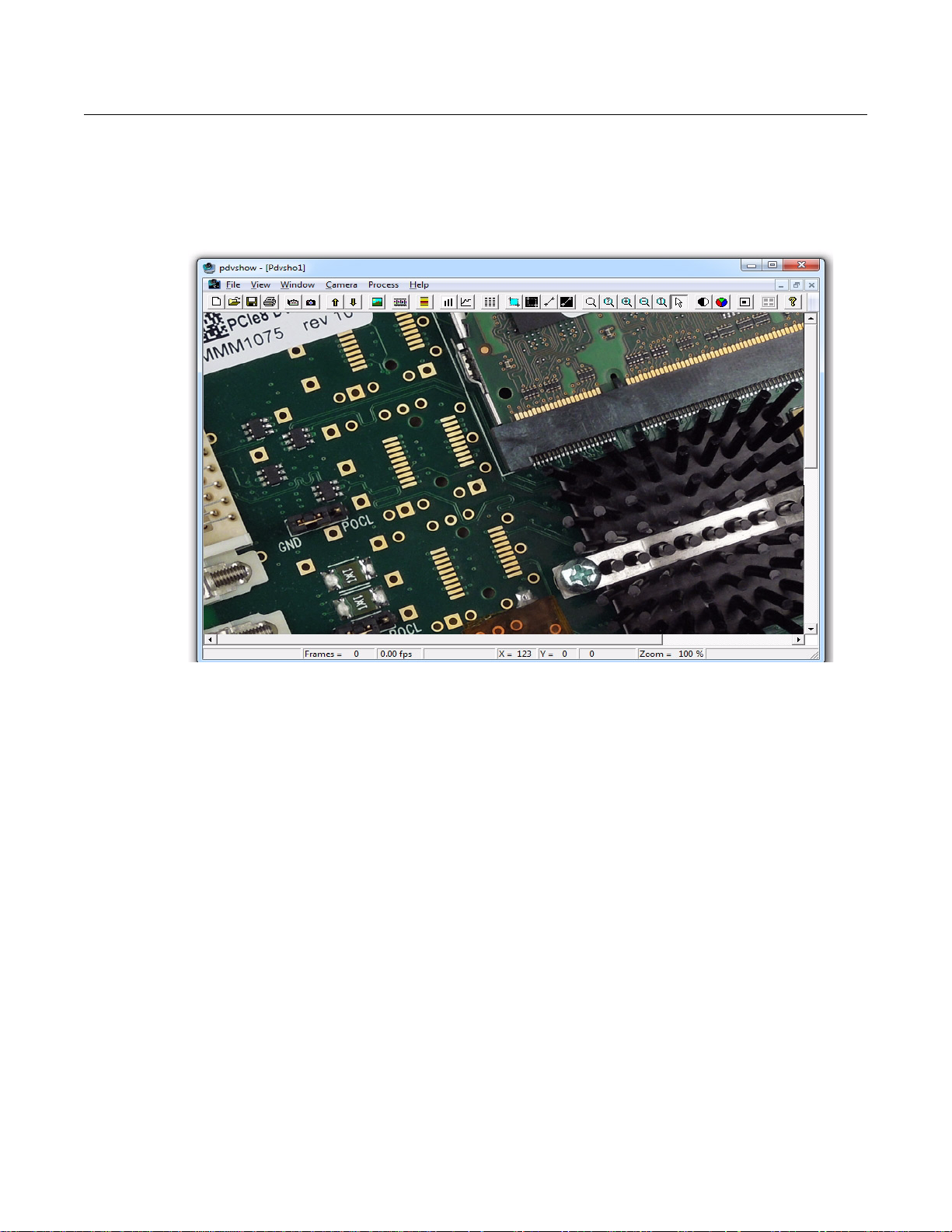
Image Capture and Display
For capturing and displaying images, your EDT software conta ins a GUI in an application called PdvShow.
The Windows version of this GUI is shown in Figure 1.
Figure 1. Windows GUI for PdvShow
Running PdvShow
To run PdvShow...
• For Windows, double-click the PdvShow desktop icon, or enter
• For Linux, run
• For Mac OS, there is no PdvShow, but you can experiment by exploring this user’s guide and the
pdv_flshow
The command-line invocation allows you to specify options – for example...
pdvshow -pdvU_C
...where U is the unit number (useful if you have more than one Camera Link PCIe device) and C is the
DMA channel number for multichannel devices. For example...
pdvshow -pdv0_1
...runs PdvShow using board 0, DM A channel 1. This is useful if, for example, you are u sing one board with
two base-mode cameras, and you want PdvShow to access the camera on DM A channel 1.
NOTE In Windows, the command line is a property of the icon.To use an icon to access a unit or DMA channel
other than 0 (the default): copy and rename the PdvShow icon; then change its shortcut properties to
use the command line with the option
make pdvshow to build the FLTK application, and then enter pdvshow at the prompt.
subdirectory of the main distribution directory (by default, /opt/EDTpdv).
-pdvU_C where U is the unit and C is the DMA channel.
pdvshow at a command-line prompt.
EDT, Inc. 2012 March 16 6
Page 12

Camera Link PCI Express (PCIe) Gen1 Framegrabbers Image Capture and Display
For demonstration or debugging purposes, you can run this application when no bo ard is installed in the
system; the image window then shows a test pattern. To do so, at the command line, enter...
initcam -u dmy0 -f configuration_file
pdvshow -dmy0
If you have not yet initialized the driver, select your camera or simulator from the list and click OK.
If the image window shows incorrect data (usually because the camera model has been chan ged since the
last driver initialization), select Camera > Setup to select the correct camera model.
To access camera controls, use the PdvShow toolbar and menus. For details, see PdvShow Help.
Compiling PdvShow
To experiment with example code in this application, use the source code indicated below.
• For Windows, look in
README file in the pdvshow subfolder of the main distribution folder (by default, C:\EDT\Pdv).
pdvshow in the appropriate Visual Studio project subfolder. For details, see the
NOTE The
unless you wish to experiment with the source code.
• For Linux, see the source code and the
tribution directory (by default,
• For Mac OS, there is no PdvShow, but you can experiment by exploring the information in this guide.
For more about the cross-platform FLTK-based version of PdvShow, see
subdirectory of the main distribution directory (by default, /opt/EDTpdv).
If the open-source FTLK library (required by
it. If the installation fails, you will need to install FLTK 1.1.9 by hand.
To install FLTK 1.1.9:
1. In
gunzip fltk-1.1.9-source.tar.gz
tar –xf fltk-1.1.9-source.tar
...to install fltk-1.1.9.
2. In
fltk-1.1.9, run...
make
make install
3. In pdv_flshow, run...
pdvshow executable comes already built on Windows distributions, so you need not compile it
README file in the pdv_flshow subdirectory of the main dis-
/opt/EDTpdv).
README in the pdv_flshow
pdv_flshow) is not installed, make pdvshow will try to install
pdv_flshow, open fltk-1.1.9-source.tar.gz and run...
make pdvshow
EDT, Inc. 2012 March 16 7
Page 13
Camera Link PCI Express (PCIe) Gen1 Framegrabbers Units, Connectors, and Channels
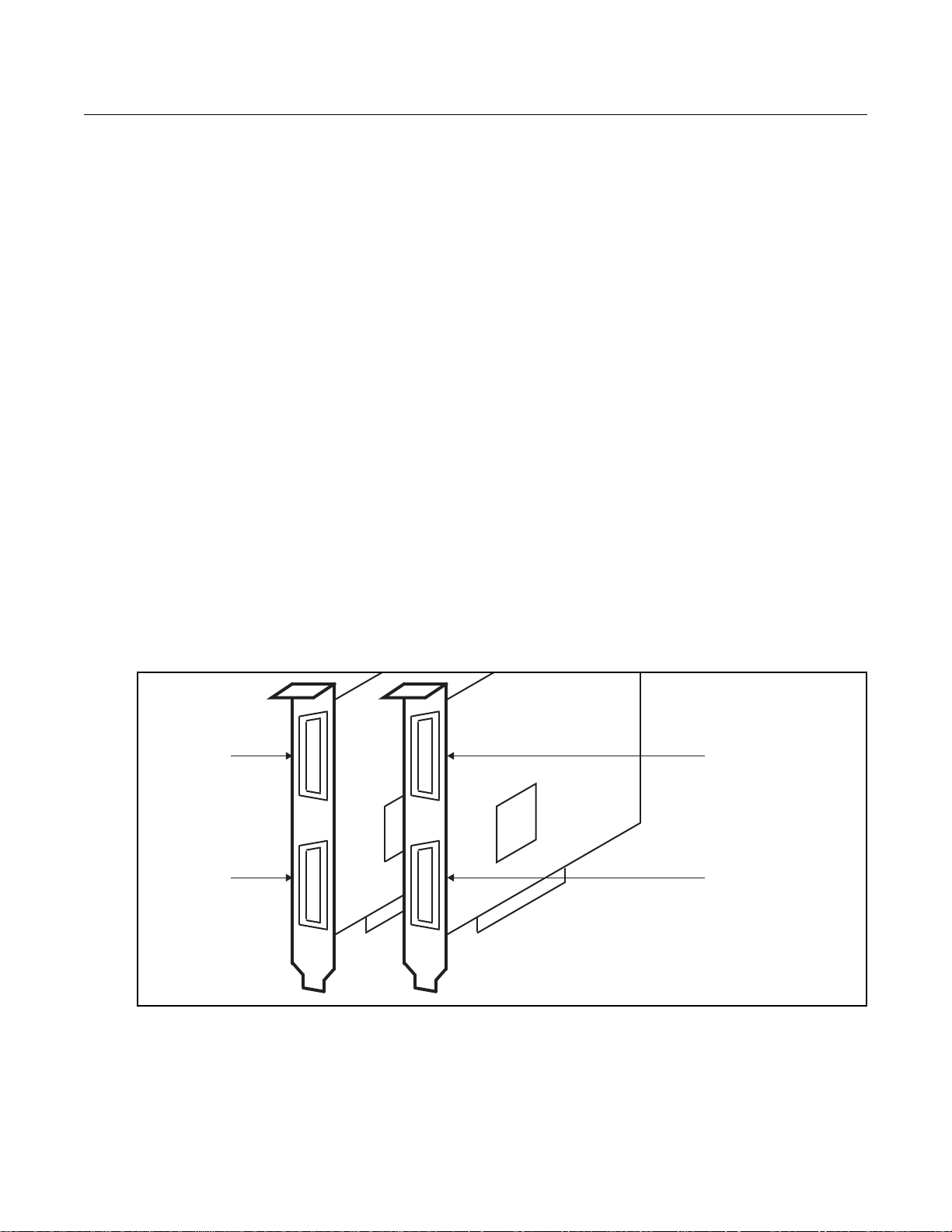
Unit 0,
Connector 0
(primary)
Unit 0,
Connector 1
(secondary)
Unit 1,
Connector 0
(primary)
Unit 1,
Connector 1
(secondary)
Unit ordering is system-dependent, starting with unit 0.
Connector ordering always starts with the connector nearest
the PCIe bus, which EDT software always calls connector 0.
Units, Connectors, and Channels
This section covers how to work with multiple units, connectors, and channels, which are defined as follows:
unit EDT product (board)
connector physical connector (for example, a fiberoptic or MDR26 connector)
channel DMA channel or, sometimes, simulation channel
Typically, an EDT Camera Link (C-Link) board has two MDR26 connectors and one simulation channel,
while an EDT fiberoptic (FOX) board has one to four fiberoptic connectors with no simulation channel.
In base mode, each camera requires one connector on the EDT board, and each connector provides one
DMA channel. Thus, in base mode, an EDT framegrabber with two connectors has two DMA channels.
In medium or full mode, each camera requires two connectors on the EDT board. In this case, the two
connectors work together to support one DMA channel.
NOTE In EDT hardware, the connectors are labeled 0 and 1 on some boards, but 1 and 2 on others.
Regardless of the labels on the hardware, the software always counts the connectors in order as 0
(primary), 1 (secondary), and so on, with 0 being the connector closest to the PCIe bus.
If you install one board in your host system, the system will assign the default unit number (0) to that board.
If you install multiple boards, the system will assign a unique unit number to each board, starting with 0 (the
sequence is system-dependent). Typically, the unit number is an argument when invoking an application
(such as
take or pdvshow) or a parameter passed into one of the EDT subroutines.
Figure 2 shows an example of how the software numbers the units ( boards) and connectors. The defa ult for
the first unit number, connector number, and DMA channel number is always 0, with additional units,
connectors, and DMA channels numbered as 1, 2, and so on.
Figure 2. Example of Unit Numbering and Connector Numbering
EDT, Inc. 2012 March 16 8
If your EDT board is connected to multiple cameras, the software provides a unique handle to represent
each camera. Unless you specify a different unit number, DMA channel number, or both, any application
(either your own or EDT’s) seeking access to the cameras will default to unit 0, connector 0.
Page 14

Camera Link PCI Express (PCIe) Gen1 Framegrabbers Serial Communication
The way that you address the appropriate unit and DMA channel will depend on what you are doing.
• For pdvshow, use the argument
-pdvU_C. For details, see Image Capture and Display on page 6.
• For EDT example and utility applications, use the arguments
ple and Utility Applications).
• For EDT API, use
return a pointer to the structure that represents the opened device (unit and DMA channel); this pointer
appears in EDT examples and documentation as
opened and manipulated independently by passing the appropriate pointer to the library subroutines.
For details, see the EDT API (Related Resources on page 2).
pdv_open_channel(..., unit, channel). For each device, the open routine will
Serial Communication
Most cameras have a manufacturer-defined serial command set for camera control and status. To utilize
this capability, EDT boards implement serial transmit and receive using standar d serial lines as defined by
the Camera Link specification. You can use serial communication in a number of ways, as discussed below.
At Initialization
As mentioned in Setting the Camera Model on page 5, the initialization process uses directives in a
configuration file to set the board registers and the driver variables to match your camera model and your
operating mode. Additional directives (especially
other
serial_* directives) can be used to send serial commands when the system is initialized. These are
described in the EDT Camera Configuration Guide (see Related Resources on page 2).
EDT provides several example configuration files that contain the ser ial commands needed to put a camera
into the desired mode. You can edit these commands or copy them to a new configuration file.
-u unit and -c channel (see Exam-
pdv_p. Each unit / channel combination can be
serial_baud, serial_init, serial_binit, and
For suggestions, see comments in the example configuration files
(where X is replaced by a specific bits-per-pixel value – for example, generic8cl.cfg) in the EDT
installation package.
From Command Line
The command-line utility serial_cmd, described in serial_cmd on page 12, allows you to send serial
commands to a camera and receive its response, in either ASCII or hexadecimal format. Command-line
help also can be accessed by entering
If you wish to incorporate this functionality in your own application, see the source code provided in
serial_cmd.c
in the EDT installation package.
serial_cmd --help.
From PdvShow
In the PdvShow application, in the Camera menu, select Programming. The resulting dialog allows you to
send and receive serial commands from the camera. For details, see Image Capture and Display on page 6.
From a Camera Manufacturer’s Application
Most Camera Link camera makers supply a Windows-based gr aphical camera con trol appl icatio n that lets
you send and receive serial commands using a framegrab ber-specific serial dynamic link library (DLL). Your
camera_config/genericXcl.cfg
EDT, Inc. 2012 March 16 9
Page 15

Camera Link PCI Express (PCIe) Gen1 Framegrabbers Example and Utility Applications
EDT installation package provides a DLL named clseredt.dll which, per the Camera Link 2.0
specification, is installed at:
•
%PROGRAMFILES%\Cameralink\Serial (64-bit version); or
•
%PROGRAMFILES(X86)%\CameraLink\Serial (32-bit version)
Camera GUIs typically provide some method for specifying the DLL pathname; for details, see your camer a
documentation.
If it becomes necessary to rename the file or copy it to a different location, be sure to recopy any newer
versions of the file to the appropriate location whe n you reinstall the EDT installation package.
From Your Application
To see all of the routines needed for user applications to send and receive serial commands: In the EDT
API (see Related Resources on page 2), follow the link to the EDT Digital Imaging Library, and then —
under Modules at the bottom of the page — to Communications / Control.
Example and Utility Applications
pciload
initcam
EDT provides a variety of example, utility, and diagnostic applications. All can be run from the command
line, using Unix-style options and arguments.
To help those developing Camera Link PCIe applications, C source code is provided for all the examples.
The source code file is the name of the application with a
For those just beginning, we recommend starting with the source for
as those applications are the easiest to understand.
The most commonly useful options for these progr ams are describ ed below. Placeholders shown in italics
should be replaced with your own values.
For a complete list of usage options, at the command line, enter the application name with the
option to display the help message.
Used to query the boards or, optionally, to update and verify the board’s flash PROM. After installation, you
may want to run
did install correctly. To use
Command-line utility that initializes the board and device driver for a specific camera. It initializes board
registers; sets various parameters (width, height, depth, etc.) to specific values; and optionally sends serial
initialization commands to the camera from the referenced configuration file. The EDT configuration files are
in your installation directory under
pdvshow, camconfig) are simply wrappers to provide a way to select the correct file, then shell out to call
initcam
detailed description of configuration files and directives, consult the Camera Configuration Guide (see
Related Resources on page 2).
Several of the most useful options are...
. To initialize from your own application code, you can use initcam.c as example code. For a
-f pathname The (required) name of the configuration file to use for initialization.
pciload with no arguments and review the output to help verify that the board and driver
pciload to update and verify the flash PROM, see Firmware on page 17.
camera_config. The EDT camera selector GUI applications (e.g.
.c extension (e.g., “take.c”).
simple_take or simplest_take,
--help
-u unit The unit number, if multiple boards are installed; default is 0 (first board).
EDT, Inc. 2012 March 16 10
Page 16

Camera Link PCI Express (PCIe) Gen1 Framegrabbers Example and Utility Applications
take
-c channel
The DMA channel, on multichannel boards; default is 0 (first channel).
Example:
initcam -f camera_config/generic8cl.cfg
Used to acquire images and (optionally) save them to files. Though it does not display the images, it does
provide many other options, making it a useful diagnostic tool. The source also shows how to change
camera settings such as integration time; tune image acquisition in certain ways; and detect errors.
Several of the most useful options are:
-b file The base name of the file in which to sa ve the image, in Sun r aster format
on Linux or Mac OS systems, or in Windows bitmap format on Windows
systems (note – in EDT software packages later than 5.3.3.3, this option
always will create files in Windows bitmap format, regardless of which
operating system you are using). If only one image is taken, this is the
filename; otherwise a two-digit number is appended to each file, starting
with 00. The appropriate suffix is automatically added.
-c channel The DMA channel, on multichannel boards; default is 0 (first channel).
-f file The name of the file in which to save the image, in raw format. The file
includes only raw image data, with no formatting information.
-l loopcount The number of consecutive pictures you wish to take. The default is one.
-N numbufs The number of ring buffers (default is 1). A ring buffer is a portion of host
memory preallocated for DMA and used in round-robin fashion. A setting
of four optimizes pipelining — one ring buffer currently acquiri ng data, one
ready for data, one getting ready, and one backup.
Example: To acquire 100 images as quickly as possible using four ring buffers with out saving to files, enter:
Example: If you have one PCIe8 DVa C-Link board connected to two b ase-mode cameras, and you wish
take
simple_take
Shows how to use the API to acquire images from a camera con nected to the Camera Link PCIe boar d and
(optionally) save the images to files.
To add image acquisition to an application, EDT recommends starting with this example, which shows how
to use the ring buffer routines to improve performance by pipelining image acquisition and processing.
Several of the most useful options are:
-u unit The unit number, if multiple boards are installed; default is 0 (first board).
-v Turns on verbose mode. The default is off.
take -N 4 -l 100
to use the camera on DMA channel 1, enter:
take -u 0 -c 1 -N 4 -l 100
-b file The base name of the file in which to sa ve the image, in Sun r aster format
on Linux or Mac OS systems, or in Windows bitmap format on Windows
systems (note – in EDT software packages later than 5.3.3.3, this option
always will create files in Windows bitmap format, regardless of which
operating system you are using). If only one image is taken, this is the
filename; otherwise a two-digit number is appended to each file, starting
with 00. The appropriate suffix is automatically added.
EDT, Inc. 2012 March 16 11
Page 17

Camera Link PCI Express (PCIe) Gen1 Framegrabbers Example and Utility Applications
-c channel
-l loopcount The number of consecutive pictures you wish to take. The default is one.
-N numbufs The number of ring buffers — by default, one. (A ring buffer is a portion of
-u unit The unit number, if multiple boards are installed; default is 0 (first board).
Example: To acquire four images as fast as possible using four ring buffers, saving each to files named
picture00.bmp
simple_take -N 4 -l 4 -b picture
simplest_take
The simplest example application. It sets up four ring buffers an d acquires a single image, with no pipelining.
simplest_take accepts an optional argument of a file name to which to save the image. If no name is
supplied, it reports a successful image acquisition, or any errors that occurred — useful for testing.
Example: To acquire an image and save it to a file named
simplest_take -b pic.bmp
simple_sequence
Like
simple_take but, instead of capturing and saving one file at a time, it captures a finite number of
images (limited to available memory) into memory and then writes them all out at once. See
for the most commonly used options.
The DMA channel, on multichannel boards; default is 0 (first channel).
host memory preallocated for DMA and used in round-robin fashion.) A
setting of four optimizes pipelining — one ring buffer currently acquiring
data, one ready for data, one getting ready, and one backup.
through picture03.bmp on Windows (or .ras on Linux / Mac OS), enter...
pic.bmp, enter...
simple_take
simple_irig2
Example of capturing images using the IRIG2 timestamp header. Can be usef ul even if an IRIG time signal
is not present, since it can be used to "tag" the beginning of an image with an image count and magic
number – to verify that image data has not been lost (loss of sync detection). See
most commonly used options.
serial_cmd
Sends serial commands to a camera through the board, using calls to routines in the API. By default, the
application starts in command mode: the final argument to
camera. Delimit this command with either single or double quotation marks, but be consistent. For exampl e:
If you omit the command argument, the application enters interactive mode, in which you can type one
command per line. To quit the application, enter Control-C.
Several of the most useful options are:
simple_take for the
serial_cmd is the command to send to the
serial_cmd "MDE?"
-c channel The DMA channel, on multichannel boards; default is 0 (first channel).
-u unit The unit number, if multiple boards are installed; default is 0 (first board).
-x Treats the command argument as a hexadecimal number, which is sent to
the camera without terminating nulls or carriage returns. The default is
ASCII with a terminating carriage return added.
EDT, Inc. 2012 March 16 12
Page 18

Camera Link PCI Express (PCIe) Gen1 Framegrabbers Triggering
Example (command mode usage):
% serial_cmd "MDE?" (Redlake "Query Mode" command)
MDE TR (camera response)
%
Example (interactive mode usage):
% serial_cmd
>MDE? (Redlake "Query Mode" command)
MDE TR (camera response)
>
% serial_cmd -x
> 03 06 02 (camera-dependent command)
> Control-C (end the program)
(for hexadecimal arguments)
To access a camera on DMA channel 1, enter:
% serial_cmd -u 0 -c 1 "MDE?"
(Redlake "Query Mode" command)
MDE TR (camera response)
%
dvinfo
Gathers board-specific and system-specific technical data, runs several diagnostics, and writes the results
to
dvinfo.out in the current directory. Use the resulting ASCII text file to dia gno se pr ob lems you rself, or
send the file to EDT for technical support.
To run
dvinfo:
1. Connect and power on the camera.
2. If possible, initialize the board with
3. Make sure no other PDV applications (such as
4. Run
dvinfo.
One useful option is:
-u unit The unit number, if multiple boards are installed; default is 0 (first board).
Triggering
This section describes the most common triggering methods for your Camera Link PCIe board, as well as
each mode’s configuration file directives, serial control commands, and software considerations. You can
change trigger modes either directly in your application, or by using configuration file directives.
• For details on camera configuration directives, see the EDT Camera Configu ration Guide (Related Re-
sources on page 2).
• For details on specific serial control commands, see your camera manual.
By default, most cameras power up in continuous (also called freerun) mode, sending images continuously.
For most cameras, EDT provides configuration files for freerun mode. For some cameras, EDT also
provides configuration files for internal triggered, external triggered, or pulse-width mode. All of these modes
and configuration details are described below.
initcam or pdvshow.
pdvshow) are running.
EDT, Inc. 2012 March 16 13
Page 19

Camera Link PCI Express (PCIe) Gen1 Framegrabbers Triggering
Freerun (Continuous)
In this mode, the camera acquires images continuously without waiting for a trigger signal.
Configuration file directives:
MODE_CNTL_NORM: 00 (default)
serial_init: as needed to set freerun mode (usually not necessary because
most cameras power up in freerun by default)
Triggered by EDT Board
In this mode, the camera waits for a trigger signal from your EDT board before acquiring an image.
Configuration file directives:
MODE_CNTL_NORM: 10
serial_init: as needed to put the camera in triggered mode
Pulse-width Triggered (Controlled or Level)
In this mode, exposure duration is determined by how long the EXPOSE line is held TRUE (high).
Configuration file directives:
API subroutine:
For cameras with very fast shutters that accept exposure times in microseconds, another configuration file
directive tells
Configuration file directive:
API subroutine:
pdv_set_exposure to use microseconds instead of milliseconds.
MODE_CNTL_NORM: 10
method_camera_shutter_timing: AIA_MCL
serial_init: as needed to put the camera in pulse-width mode
pdv_set_exposure, millisecond units, range 0–25500
MODE_CNTL_NORM: 10
method_camera_shutter_timing: AIA_MCL_100US
serial_init: as needed to put the camera in pulse-width mode
pdv_set_exposure, microsecond units, range 0–25500
External Trigger Direct to Camera
With this method, the trigger is sent from an external source directly to the camera, bypassing the board.
The camera and board can be configured as in freerun mode; however, depending on timing, your
application may time out and fail to receive images. You can avoid timeouts in either of two ways:
• If the maximum period of time between triggering signals is known, configur e the
in the software for a large enough value to avoid timeouts.
• If application blocking is acceptable, configure the
period (
Configuration file directive:
API subroutine:
Be sure to comply with Requirements on page 3. If you have trouble, consult Troubleshooting on page 20.
EDT, Inc. 2012 March 16 14
user_timeout=0) to ensure that the application waits until an image arrives.
MODE_CNTL_NORM: 00
user_timeout as needed to ensure that your application does not time out while
waiting for an image
pdv_set_timeout, millisecond units
user_timeout period in the software for an infinite
user_timeout period
Page 20

Camera Link PCI Express (PCIe) Gen1 Framegrabbers Simulation and Testing
External Trigger Pass-through
With this method, a trigger is sent from an external device to the board, and from the board to th e camera .
A TTL signal is input to the board, which in turn sends out an LVDS or RS422 signal (depending on the
board and its configuration) to the camera trigger line, typically CC1.
Configuration file directives:
API subroutine:
The software timeout considerations are the same as those under External Trigger Direct to Camera.
Be sure to comply with Requirements on page 3. If you have trouble, consult Troubleshooting on page 20.
External Triggering Pins
The pins to which you connect the trigger source are shown in Appendix B: Board Diagrams.
With two cameras, trigger input 0 can trigger both cameras, or triggers 0 an d 1 can trigger cameras 0 and
1 independently; for details, see configuration file directives (above).
Fire the trigger by applying a TTL signal lasting at least 10 microseconds to these pins, which in tur n send
a signal of the appropriate level to the camera trigger line, typically CC1. The trigger cable can drive either
pin high with respect to the other; no particular polarity is required.
The two pins of each trigger drive a Vishay SFH6206 optocoupler through a 130- series resistor. This
optocoupler is provided to allow coupling to electromechanical systems in which major ground spikes can
occur when electrical devices such as motors, for example, turn on or off.
MODE_CNTL_NORM: A0
CL_CFG2_NORM as needed to set separate or combined triggers from trigger 0
pins
user_timeout as needed to ensure that your application does not time out while
waiting for an image
pdv_set_timeout, millisecond units
Simulation and Testing
EDT Camera Link PCIe boards (excluding the FOX boards) include a channel 2 simulator for generating
sample data with no camera attached to the board (useful for testing the board hardware). This channel
uses a simple counter to generate 16-bit pixel data; pixels start black and fade to white, as in Figure 3.
EDT, Inc. 2012 March 16 15
Page 21

Camera Link PCI Express (PCIe) Gen1 Framegrabbers Simulation and Testing
Figure 3. Simulated Channel 2 Test Image in PdvShow
Data is generated as fast as the bus speed allows:
• On a four-lane PCI Express bus, 680 MB/s;
• On an eight-lane PCI Express bus with a maximum payload of 128 bytes, 1.1–1.4 GB/s.
To use the channel 2 simulator with
pdvshow, follow the steps below.
1. Start the application with:
pdvshow -pdv0_2
2. Select the Camera Setup menu item.
3. Select the desired configuration.
To use the channel 2 simulator with your own application:
1. Use the initialization application
initcam, specifying channel 2 and the camera configuration file for
your camera. From a command prompt, enter:
initcam -c 2 -f camera_config/yourCamera.cfg
...replacing yourCamera with the appropriate configuration file name for your camera and application.
NOTE For general testing, use one of the
2. Open the device with a call to
pdv_open_channel, passing it NULL for the device, yo ur va lue for t he
board unit number, and 2 for the channel – as in this example (showing a board with a unit numbe r of 0):
PdvDev *pdv_p = pdv_open_channel(NULL, 0, 2);
The pointer returned from this call points to the simulated data; any image acquisition calls, such as
pdv_wait_image,
that pass this pointer will access the simulated data.
genericXXcl.cfg files provided with your board.
Because data is generated as fast as possible, you can also use the channel 2 simulator to measure the
maximum bus bandwidth, using the utility application
cl_speed. This utility takes the unit number as an
argument and begins channel 2 simulation on the specified boar d; it then reports the data speeds achieved.
EDT, Inc. 2012 March 16 16
Page 22

Camera Link PCI Express (PCIe) Gen1 Framegrabbers Firmware
Firmware
At times, you may need to reprogram the PCI / PCIe interface flash memory using pciload – for instance:
• if you want to switch from one mode to another (base, medium, full) on certain EDT boards;
• if you want to convert an EDT simulator into a framegrabber, or vice versa;
• if you need to use an FPGA configuration file that has special functionality;
• if you upgrade to a new installation package that includes a required update for your board; or
• if the firmware becomes corrupted.
To do so, follow the instructions in the sections below.
Checking and Loading the Firmware
The following procedure applies to standard firmware only. If you are running a custom fi rmware file and
need to update it, first get a custom firmware configuation file from EDT.
NOTE Do not upgrade the firmware simply because you see a newer firmware file with a new driver; instead,
consult the
README file in the package, which will tell you if there is a necessary upgrade.
• For Windows,
a command shell in the installation directory
• For Linux / Mac OS, pciload is an application in /opt/EDTpdv.
To see currently installed and recognized EDT boards and firmware, ente r:
pciload
The program outputs the date and revision number of the firmware in the flash memory.
To compare the PCI / PCIe firmware in the package to the firmware loaded in flash on the board, enter:
pciload verify
If the two match, the firmware on the board is the same as the firmware in the installation package. If they
differ, you’ll see error messages, but these do not necessarily indicate problems; if your application is
working correctly, you probably do not need to upgrade the firmware.
If you do wish to update the standard firmware, enter:
pciload update
To upgrade or switch to a specific firmware file, enter:
pciload firmware
...replacing firmware
extension.
Example: To load full-mode firmware on a PCIe8 DVa C-Link board, run...
pciload pe8dvacamlk
pciload is an application in \EDT\Pdv. Double-click the Pdv Utilities icon to bring up
\EDT\Pdv.
with the filename of the desired firmware, up to but not including the .bit
The board reloads the firmware from the flash memory only during powerup – so after running pciload,
the old firmware is in the PCIe FPGA until the system has power-cycled.
NOTE Updating the firmware requires cycling power, not simply rebooting.
EDT, Inc. 2012 March 16 17
Page 23

Camera Link PCI Express (PCIe) Gen1 Framegrabbers Firmware
For a list of all pciload options, see the tables below or enter:
pciload --help
NOTE When using the tables below, use only Table 3 for current boards (with “DVa” in their names) and only
Table 4 for legacy boards (with “DV” but no “a” in their names). The firmware is not interchangeable.
Table 3. Arguments to pciload for current boards (with “DVa” in their na mes )
Board name Command Notes
PCIe4 DVa FOX pciload pe4dvafox (base mode)
pciload pe4dvafox_fm (full mode)
PCIe4 DVa CLink
PCIe8 DVa CLink*
* To find and load the firmware that converts this framegrabber into a PCIe8 DVa CLS simulator, consult the EDT
Simulator User’s Guide (see
Table 4. Arguments to pciload for legacy boards (with “DV” but no “a” in their names)
Board name Command Notes
PCIe4 DV C-Link pciload pedvcamlk32 (base mode)
PCIe8 DV C-Link
(rev. 10 or lower)
PCIe8 DV C-Link
(rev. 11 and up)
pciload pe4dvacamlk (base or medium mode)
pciload pe8dvacamlk (base mode)
pciload pe8dvacamlk_fm (medium or full mode)
Related Resources on page 2).
pciload pe4dvcamlk32_mm (medium mode)
pciload pe8dvcamlk (base or medium mode)
pciload pe8dvcamlk_fm (full mode)
pciload pe8dvcamlk2 (base or medium mode)
pciload pe8dvcamlk2_fm (full mode)
EDT recommends using base / medium
firmware for base / medium mode cameras.
However, if you have just one framegrabber
and are switching between base / medium
mode and full mode, you can use use fullmode firmware with one base- or mediummode camera of 40 MHz or more.
(no full-mode firmware provided)
EDT recommends using base / medium
firmware for base / medium mode cameras.
However, if you have just one framegrabber
and are switching between base / medium
mode and full mode, you can use use fullmode firmware with one base- or mediummode camera of 40 MHz or more.
Corrupted Firmware
In rare cases, the board firmware may become corrupted. Typically, the symptom is that the board is not
recognized by the operating system, or the computer itself will not boot with the board in it. In such cases,
booting from the protected (backup) sector will allow the board to be seen so that you can reprogram the
programmable sector.
Each EDT framegrabber has both a protected (backup) and a programmable fla sh memory boot sector. The
sector from which the board will boot is determined by a jumper, which is preset to the programmable sector.
If that sector becomes corrupted, you can move the jumper so the board will boot from the protected sector.
Most often, firmware corruption is the result of an interrupted load process or an unanticipated interaction
with the host computer; if so, following the procedure below should solve the problem.
If the firmware file itself has become corrupted, first contact EDT for the current firmware you’ll need to
replace it, and then follow this procedure.
To reboot from the protected sector:
1. If needed, move the new firmware file to the directory in which you installed the EDT software.
2. Power down the host and board.
3. To avoid later confusion, remove any other EDT boards from the host.
EDT, Inc. 2012 March 16 18
Page 24

Camera Link PCI Express (PCIe) Gen1 Framegrabbers Firmware
4. On the EDT board with the corrupted firmware, move the jumper from its programmable to its protected
setting (to locate this setting on your board, see Firmware on page 17).
5. Power up the host and board.
6. Navigate to the directory in w hic h you inst alle d th e EDT soft war e .
7. At the command prompt, enter...
pciload
The program outputs the date and revision number of the firmware in the flash memory — in this case,
the date and revision number that shipped as of your purchase date. If no erro rs are reported, you have
successfully booted from the protected sector.
8. With the system still powered up, move the jumper back to its original position.
9. Enter...
pciload firmware
...replacing
firmware with the correct filename, as indicated in Table 3 and Table 4 (above). If the
feedback shows no errors, the new firmware has been installed, although it is not yet running.
10. Power down the host and board again.
11. Power up the system.
12. Run
pciload with no arguments to verify the board is recognized and is running with the new firmware.
EDT, Inc. 2012 March 16 19
Page 25

Camera Link PCI Express (PCIe) Gen1 Framegrabbers Troubleshooting
Troubleshooting
The EDT installation package includes numerous diagnos tic programs, the most useful o f which are briefly
described in Example and Utility Applications on page 10. You can use these programs to search for
problems yourself or to generate output files to provide to EDT for technical support. For further technical
help, visit the EDT support webpage (see Related Resources on page 2).
NOTE When contacting EDT for support, always provide output from the most re levant diagnostic programs –
especially
results to the file
Board Not Seen
To verify that the firmware is installed correctly and can access each board, run pciload (in the EDT
installation package) with no arguments. You should see information on each EDT board that can be seen.
If a board is not seen by the system:
• Try uninstalling and reinstalling the EDT package (and remember to reboot after each install).
• Try moving the board to a different slot.
• Try checking for these possible problems...
dvinfo, which gathers board- and system-specific information, runs tests, and writes the
dvinfo.out in the current directory (see dvinfo on page 13).
— Typically, an EDT PCIe board will not work in a bus slot dedicated to graphics cards, or a bus slot
wired for fewer lanes than the number specified – for instance, an eight-lane board will not work
properly in a slot wired for only four lanes (see Requirements on page 3).
— EDT drivers typically will not work with “guest only” accounts, so if you are using such an account,
change to an account with greater access.
— For Windows 7 or Windows Vista, EDT installation packages prior to version 5.3.3.1 typically will
not load if your Windows User Account Control is set to the lowest (disabled) setting. In such cases,
try either disabling User Account Control or updating your EDT installation package (see Installation
on page 3).
See also Problems With Bandwidth on page 22 and Problems With Firmware on page 24.
EDT, Inc. 2012 March 16 20
Page 26

Camera Link PCI Express (PCIe) Gen1 Framegrabbers Troubleshooting
Problems With Software Installation
Many software installation problems may be solved by downloading the latest EDT installation packag e (see
Installation on page 3).
NOTE Be sure to remove any previous installation packages before installing a new or updated package.
Windows
Try any of the following:
• If a board is not recognized, use the Windows Device Manager to see if the board is present as an “unknown device.” If so, right-click on the unknown de vice and cho o se Unins tall to uninstall it; then, from
the Action menu, select Scan for Hardware Changes.
• Uninstall and then reinstall your existing EDT installation package.
• Download and install the latest EDT installation package (see Installation on page 3).
NOTE Do not extract and install files by hand; doing so will circumvent the installation process, which
automatically updates system files, establishes links, and creates new files. Similarly, do not remove
files by hand. Instead, use the Add or Remove Programs facility in the Windows control panel.
Linux
Try any of the following:
• Failure during installation may be due to system package dependencies. Make sure the fo llowing packages are installed on your system...
make
gcc
libtiff
linux kernel headers
For example, on Ubuntu, you would install the libtiff library by running...
sudo apt-get install libtiff4-dev
After all needed packages are in place, running make from the /opt/EDTpdv directory should complete
installation.
• Uninstall and then reinstall your existing EDT installation package. To unin stall, use the programs in the
/opt/EDTpdv
— If the package was installed using
— If the package was installed using rpm --install package, remove it with rpm -erase pack-
age
• Download and install the latest EDT installation package (see Installation on page 3).
NOTE New Linux versions often require an updated device driver, so if you are using a new or updated Linux
kernel and you have trouble with the EDT installation or device access, check to see if a new EDT
installation package is available.
installation directory...
package.run, remove it with ./uninstall.sh.
.
EDT, Inc. 2012 March 16 21
Page 27

Camera Link PCI Express (PCIe) Gen1 Framegrabbers Troubleshooting
Mac OS
Try any of the following:
• Verify that you are using the appropriate EDT installation package for your version of Mac OS...
— For Mac OS versions 10.6 and higher, use EDT 5.x packages.
— For Mac OS versions 10.5 and lower, use EDT 4.1.9.6 package.
• Uninstall and then reinstall your existing EDT installation package. Before doing so, uninstall existing
EDT installation directories by renaming or deleting them. Typically they are found at...
—
/Applications/Edt/pdv
— /Applications/Edt/pcd
• Download and install the latest EDT installation package (see Insta llation on page 3). Before doing so,
uninstall existing EDT installation directories by renaming or deleting them. Typically they are found at...
—
/Applications/Edt/pdv
— /Applications/Edt/pcd
Corrupted Images, Slow Acquisition, Timeouts, Data Loss
Corrupted images, slow acquisition rates, repeated timeouts, or data loss usually indicate that the bus is to o
slow or the driver is misconfigured. To correct this issue:
• Verify that the camera configuration file is the correct one for your camera and operating mode; see Set-
ting the Camera Model on page 5.
• Verify that the EDT board is in a PCIe slot that is wired electrically (not just physically) to support the
number of lanes provided by the board. For example, an EDT x8 board requir es a slot that is x8 or x16,
while an EDT x4 board requires a slot that is x4, x8, or x16. Also, note that some motherboards will “split”
lanes between two slots, so that two x8 slots will become x4 if both are occupied.
• Determine the bandwidth required by your camera, and then ensure that both the board and the host
can sustain the required throughput. For fastest full-mode cameras, your framegrabber and your host
bus both must support eight lanes. For multiple camera installations, the combined data rates should
not exceed that of the board(s) installed.
• Verify that the firmware file you loaded is the correct one for your camera and your mode of operation
(base, medium, or full mode); see Firmware on page 17.
• Eliminate other devices, if any, that may be reducing the available bus bandwidth.
•Consult Requirements on page 3 to verify that your setup meets bus and throughput requirements.
• When updating to a new device driver, always recompile and relink applications that use EDT libraries
(see Firmware on page 17).
For more information, see Problems With Bandwidth.
Problems With Bandwidth
To prevent timeouts and data loss caused by bandwidth problems, you’ll need to determine the bandwidth
required by your camera and verify that the board and the host system can sustai n the required throughput.
Bandwidth requirements depend on the camera’s pixel clock speed, the number of bytes per pixel, the
number of taps, and the number of DMA channels. To calculate ban dwidth requirements, use this equa tion:
EDT, Inc. 2012 March 16 22
Page 28

Camera Link PCI Express (PCIe) Gen1 Framegrabbers Troubleshooting
pixel clock speed * taps * bytes/pixel = total bandwidth
NOTE The pixel clock speed, not the frame rate, affects bandwidth requirements. If data loss is a problem,
increasing the delay between frames probably will not help.
Cameras that output 10–16 bits per pixel will require two bytes per pixel of bandwidth. Therefore, a camera
that has a 40 MHz pixel clock, two taps, and 12 bits per pixel requires system bandwidth of:
40 * 2 * 2 = 160 MB per second
You can ease this constraint by running the camera in a less demanding mode — for example, you can
often run two-tap cameras in single-tap mode, or 12-bit cameras in 8-bit mode.
Other tips on solving bandwidth problems include:
•Consult Requirements on page 3 to verify that your setup meets bus and throughput requirements.
• Consider the number of cameras and the speed of th e cameras you are using. The bus bandwid th may
be adequate for some configurations, but inadequate for configurations with more or faster cameras.
• Consider the number of framegrabbers or other devices connected to the bus; using multiple devices
on a single bus can reduce bandwidth, sometimes considerably.
• Verify that your bus has the required number of (fully connected and usable) lanes: at least four lanes
for the 4-lane boards, and at least eight lanes for the 8-lane boards.
• Note that the legacy PCIe4 DV C-Link has a maximum bandwidth of about 200 MB/s (due to bridging
issues between PCI and PCIe). If you have bandwith problems with this legacy “DV” board, consider
upgrading to a newer “DVa” version – either x4 (PCIe4 DVa C-Link) or x8 (PCIe8 DVa C-Link).
Problems Acquiring Images With EDT Applications
If you have problems with image acquisition when using EDT applications, try the suggestions below.
• Verify that the camera device is on and is receiving power.
• Verify that all interface cable connections are working properly: Turn off the camera, unplug the cable
at both ends, reattach the cable at both ends, and turn on the camera again.
• Try a different cable, if available.
• Try a different camera, if available.
• Verify that the EDT installation package was installed correctly and that the driver is running and can
see the board. To do so, in the EDT installation directory, go to the command line and enter:
pciload
If you see no information about your EDT board, then a problem occurred during installation.
To resolve it, one at a time, try:
— cycling system power;
— moving the board to a different slot;
— uninstalling and reinstalling the driver.
For best performance, install your EDT board in a bus that is not shared with any other devices and that
meets the board’s speed requirements, as discussed in Requirements on page 3.
EDT, Inc. 2012 March 16 23
Page 29

Camera Link PCI Express (PCIe) Gen1 Framegrabbers Troubleshooting
Problems With Your Applications
A mismatch between driver and library software versions can cause application or system failures in your
applications that use EDT libraries. When updating to a new device driver, always recompile and relink
applications that use EDT libraries.
Use the PDVDEBUG and EDTDEBUG environment variables to enable debug console outp ut from the EDT
libraries. Both libraries are documented on the EDT website.
Applications that use the EDT digital imaging library can set the PDVDEBUG environment variable to 1 or
2. A value of 1 turns on call trace information from most (though not all) library routines; a value of 2 enables
more verbose trace information. A value of 0 turns off debug output. Setting th e EDT DEBUG envir onmen t
variable to one or two will provide even more detailed debug output from the underlying DMA library.
The EDT Message Handler Library provides generalized error- and message-handling for EDT software
libraries and can be helpful for debugging your programs. See the EDT Message Handler Lib rary in the API
for specific routines and usage.
Before calling for technical support, reproduce the problem with one of our applications, such as
simple_take,
compare your code with ours to see if you can spot the difficulty.
A simple example program that demonstr at es th e pr ob le m is also help fu l.
or pdvshow, if possible. If you cannot reproduce the problem with an EDT application,
take,
Problems With Threads
The driver and libraries for your Camera Link PCIe product use threads. If you are using third-par ty software
that is not thread-safe, contact your third-party vendor to determine if a thread-safe version is available.
Problems With Firmware
You may need to update the PCIe interface flash memory with pciload under these conditions:
• If you install a new device driver or switch to an FPGA configuration file with special functionality;
• If your firmware becomes corrupted;
• If the board is not seen in the system or is missing functionality that is in newer boards;
• If the firmware loaded on the board does not match the camera mode.
For details, see Firmware on page 17.
EDT, Inc. 2012 March 16 24
Page 30

Camera Link PCI Express (PCIe) Gen1 Framegrabbers Appendix A: Pin Assignments
CAUTION! Never plug a non-PoCL device (camera, cable, extender, etc.) into an EDT board that
has the PoCL jumpers in the “enabled” position. Doing so will cause a short – indicated by a red
LED (which may be obscured by your backpanel) on the back of the board, near the associated
connector – and may damage your equipment.
Appendix A: Pin Assignments
Table 5 shows the MDR26 pin assignments for Camera Link signals.
Table 5. Pinout – MDR26 Connector
Camera Link signal
Camera
end
1* 1* inner shield / ground* inner shield / ground* inner shield / ground*
14* 14* inner shield / ground* inner shield / ground* inner shield / ground*
2 25 X0– Y0– Y0–
15 12 X0+ Y0+ Y0+
3 24 X1– Y1– Y1–
16 11 X1+ Y1+ Y1+
4 23 X2– Y2– Y2–
17 10 X2+ Y2+ Y2+
5 22 Xclk– Yclk– Yclk–
18 9 Xclk+ Yclk+ Yclk+
6 21 X3– Y3– Y3–
19 8 X3+ Y3+ Y3+
7 20 SerTC+ unused 100 ohms
20 7 SerTC– unused terminated
8 19 SerTFG– unused Z0–
21 6 SerTFG+ unused Z0+
9 18 CC1– unused Z1–
22 5 CC1+ unused Z1+
10 17 CC2+ unused Z2–
23 4 CC2– unused Z2+
11 16 CC3– unused Zclk–
24 3 CC3+ unused Zclk+
12 15 CC4+ unused Z3–
25 2 CC4– unused Z3+
13* 13* inner shield / ground* inner shield / ground* inner shield / ground*
26* 26* inner shield / ground* inner shield / ground* inner shield / ground*
Framegrabber
end
(base mode,
primary connector)
Camera Link signal
(medium mode,
secondary connector)
Camera Link signal
(full mode,
secondary connector)
* For PoCL, pins 1 and 26 change to +12V DC power, while pins 13 and 14 change to +12V DC power return.
EDT, Inc. 2012 March 16 25
Page 31

Camera Link PCI Express (PCIe) Gen1 Framegrabbers Appendix B: Board Diagrams
PCIe8 DVa C-Link
1
3
5
7
9
2
4
6
8
10
Berg
connector
Optional Lemo
Base 0 /
primary
Base 1 /
secondary
Connectors
FVAL
LVAL
DVAL
PCLK
DEBUG
3 2 1
5 3 1
1
NORM
NORM
PROT
ALT
6 4 2
PoCL
Disabled Enabled
3 2 1 3 2 1
FPGA boot select
Program-
mable
Protected
1
2
1
2
(sector 0) (sector 3)
PoCL
select
LEDs
3 2 1
CAUTION! To avoid a short, indicated by a red
LED near the connector, never plug a non-PoCL
cable or device into a PoCL-enabled EDT board.
= pin
= hole
= ground (pin)
= ground (hole)
Not to scale; bold = default.
slot for optional memory
PCIe8 DVa C-Link
1
3
5
7
9
2
4
6
8
10
Berg
connector
Optional Lemo
Base 0 /
primary
Base 1 /
secondary
Connectors
FVAL
LVAL
DVAL
PCLK
DEBUG
3 2 1
5 3 1
1
NORM
NORM
PROT
ALT
6 4 2
PoCL
Disabled Enabled
3 2 1 3 2 1
FPGA boot select
Programmable
Protected
1
2
1
2
(sector 0) (sector 3)
PoCL
select
LEDs
3 2 1
CAUTION! To avoid a short, indicated by a red
LED near the connector, never plug a non-PoCL
cable or device into a PoCL-enabled EDT board.
= pin
= hole
= ground (pin)
= ground (hole)
Not to scale; bold = default.
slot for optional memory
PCIe4 DVa C-Link
1
3
5
7
9
2
4
6
8
10
Berg
connector
Optional Lemo
Base 0 /
primary
Base 1 /
secondary
Connectors
FVAL
LVAL
DVAL
PCLK
DEBUG
3 2 1
5 3 1
1
NORM
NORM
PROT
ALT
6 4 2
PoCL
select
LEDs
(on back)
3 2 1
= pin
= hole
= ground (pin)
= ground (hole)
Not to scale; bold = default.
slot for optional memory
PoCL
Disabled Enabled
3 2 1 3 2 1
FPGA boot select
Program-
mable
Protected
1
2
1
2
(sector 0) (sector 3)
CAUTION! To avoid a short, indicated by a red
LED near the connector, never plug a non-PoCL
cable or device into a PoCL-enabled EDT board.
PCIe4 DVa C-Link
1
3
5
7
9
2
4
6
8
10
Berg
connector
Optional Lemo
Base 0 /
primary
Base 1 /
secondary
Connectors
FVAL
LVAL
DVAL
PCLK
DEBUG
3 2 1
5 3 1
1
NORM
NORM
PROT
ALT
6 4 2
PoCL
select
LEDs
(on back)
3 2 1
= pin
= hole
= ground (pin)
= ground (hole)
Not to scale; bold = default.
slot for optional memory
PoCL
Disabled Enabled
3 2 1 3 2 1
FPGA boot select
Programmable
Protected
1
2
1
2
(sector 0) (sector 3)
CAUTION! To avoid a short, indicated by a red
LED near the connector, never plug a non-PoCL
cable or device into a PoCL-enabled EDT board.
Appendix B: Board Diagrams
This section shows diagrams and key features for the various Camera Link PCIe boards.
Standard and Fiberoptic (FOX) Framegrabbers – PCIe “DVa”-series
PCIe8 DVa C-Link
PCIe4 DVa C-Link
EDT, Inc. 2012 March 16 26
Page 32

Camera Link PCI Express (PCIe) Gen1 Framegrabbers Appendix B: Board Diagrams
Transceiver 1
Transceiver 0
Transceiver 3
Transceiver 2
PCIe4 DVa FOX
1
3
5
7
9
2
4
6
8
10
Berg
connector
Optional Lemo
Connectors
FVAL
LVAL
DVAL
PCLK
DEBUG
5 3 1
1
NORM
NORM
PROT
ALT
6 4 2
= pin
= hole
= ground (pin)
= ground (hole)
Not to scale; bold = default.
slot for optional memory
FPGA boot select
Program-
mable
Protected
1
2
1
2
(sector 0) (sector 3)
LEDs
(on back)
NOTE - Each transceiver (up to 4) has its own
LED, which is steady green if that transceiver is
getting a valid signal.
Transceiver 1
Transceiver 0
Transceiver 3
Transceiver 2
PCIe4 DVa FOX
1
3
5
7
9
2
4
6
8
10
Berg
connector
Optional Lemo
Connectors
FVAL
LVAL
DVAL
PCLK
DEBUG
5 3 1
1
NORM
NORM
PROT
ALT
6 4 2
= pin
= hole
= ground (pin)
= ground (hole)
Not to scale; bold = default.
slot for optional memory
FPGA boot select
Programmable
Protected
1
2
1
2
(sector 0) (sector 3)
LEDs
(on back)
NOTE - Each transceiver (up to 4) has its own
LED, which is steady green if that transceiver is
getting a valid signal.
PCIe4 DVa FOX
EDT, Inc. 2012 March 16 27
Page 33

Camera Link PCI Express (PCIe) Gen1 Framegrabbers Appendix B: Board Diagrams
Base 0 /
primary
Base 1 /
secondary
Connectors
PCIe8 DV C-Link
Optional Lemo
Not to scale; bold = default.
PCLK FVAL
DVAL LVAL
Base 1 / secondaryBase 0 / primary
Triggering (external TTL)
1
Maximum # of lanes
(usually this jumper should be
left in the x8 position, even if the
board is in an x16, x4, or x1 slot)
FPGA boot select
Programmable
Protected
x8 x4 x1
Programmable
Protected
FPGA boot select
Base 0 /
primary
Base 1 /
secondary
Connectors
PCIe4 DV C-Link
Optional Lemo
Base 1 / secondaryBase 0 / primary
Triggering (external TTL)
Not to scale; bold = default.
1
Programmable
Protected
FPGA boot select
Base 0 /
primary
Base 1 /
secondary
Connectors
PCIe4 DV C-Link
Optional Lemo
Base 1 / secondaryBase 0 / primary
Triggering (external TTL)
Not to scale; bold = default.
1
Legacy Framegrabbers – PCIe “DV”-series
PCIe8 DV C-Link
PCIe4 DV C-Link
EDT, Inc. 2012 March 16 28
Page 34

Camera Link PCI Express (PCIe) Gen1 Framegrabbers Appendix B: Board Diagrams
6
5
2
3
4
7
8
9
10
1
5
6
7
1
4
2
3
Additional External Inputs
Via Berg Connector or Optional Lemo Connector
All Camera Link PCIe boards have two connectors that can be used for exter nal control (triggers a nd other
inputs): a Berg connector, or an optional seven-pin Lemo connector. Pin assignments are shown below.
BERG CONNECTOR:
LEMO CONNECTOR:
Pin
PCIe “DVa”-
series (all)
Legacy PCIe4
DV C-Link
Legacy PCIe8
DV C-Link
1 Trigger 0+ Trigger 0+ Trigger 0+
2 Trigger 0- Trigger 0- Trigger 03 Trigger 1+ Trigger 1+ Trigger 1+
4 Trigger 1- Trigger 1- Trigger 15 IRIG-B IRIG-B IRIG-B
6 3.3V Reserved Reserved
7 Reserved Ground Ground
8 Reserved Reserved Reserved
9 Reserved Reserved Reserved
10 Ground Ground Ground
Pin
PCIe “DVa”-
series (all)
Legacy PCIe4
DV C-Link
Legacy PCIe8
DV C-Link
1 Trigger 1+ Trigger 0+ Trigger 1+
2 3.3V Trigger 0- Reserved
3 Trigger 0+ Trigger 1+ Trigger 0+
4 Trigger 0- Trigger 1- Trigger 05 IRIG-B IRIG-B IRIG-B
6 Trigger 1- Reserved Trigger 17 Ground Ground Ground
EDT, Inc. 2012 March 16 29
Page 35

Camera Link PCI Express (PCIe) Gen1 Framegrabbers Appendix B: Board Diagrams
Via Optional Cable Assembly
For the PCIe8 DV / DVa C-Link and the PCIe4 DVa C-Link, there is an optional EDT-built cable assembly
for triggering, timestamping, or both; below are the pin assignments (see also Appendix C: Timestamping).
Table 6. Pin assignments – Current EDT cable assembly for triggering, timestamping, or both
EDT p/n 016-13840 (June 2010): [color] Lemo D9 Function BNC BNC Label
:
For length, Lemo to D9 = 1 ft.; three BNCs out to D9 = each 6 in. or less.
Below is a legacy version of the cable, which is supported only for legacy applications that still use it.
green 1 2 trigger 1+ center conductor TRIG 1
red 2 9 reserved – –
orange 3 7 trigger 0+ center conductor TRIG 0
brown 4 8 trigger 0- shield TRIG 0
white 5 4 IRIG IN center conductor IRIGB
blue 6 3 trigger 1- shield TRIG 1
black 7 5 ground shield IRIGB
Table 7. Pin assignments – Legacy EDT cable assembly for triggering, timestamping, or both
EDT p/n 016-02894 (legacy): [color] Lemo Function
:
For length, Lemo cable = 2 ft.; BNC cable = approximately 36 in.
green 1 –
red 2 –
orange 3 –
brown 4 –
white 5 (to center conductor of coaxi al cable)
blue 6 –
black 7 (to shield of coaxial cable)
EDT, Inc. 2012 March 16 30
Page 36

Camera Link PCI Express (PCIe) Gen1 Framegrabbers Appendix B: Board Diagrams
Secondary
Primary
Connectors /
Transceivers
EDT or
3rd-party
serial
back
panel w/
ribbon
cabling
Triggering
(external TTL)
Any EDT framegrabber
Generic representation of an EDT framegrabber. Not to scale.
Trigger pins
(board-dependent;
see individual
board diagrams)
Secondary
Primary
Connectors /
Transceivers
Generic representation of any EDT DV board. Not to scale.
EDT or
3rd-party
serial
back
panel w/
ribbon
cabling
Primary
Secondary
Triggering
(external TTL)
Any EDT DV board
Secondary
Primary
Connectors /
Transceivers
EDT or
3rd-party
serial
back
panel w/
ribbon
cabling
Triggering
(external TTL)
Any EDT framegrabber
Generic representation of an EDT framegrabber. Not to scale.
Trigger pins
(board-dependent;
see individual
board diagrams)
Via Ribbon Cabling and D9 Connectors
If you do not have the optional Lemo connector, you can use a serial backpanel equipped with ribbon
cabling and one or two 9-pin D-connectors. The diagram below illustrates the single D-connector setup.
EDT, Inc. 2012 March 16 31
Page 37

Camera Link PCI Express (PCIe) Gen1 Framegrabbers Appendix C: Timestamping
Appendix C: Timestamping
This appendix covers the timestamping function, which is provided through the optional Lemo co nnector on
the PCIe8 DV / DVa and the PCIe4 DVa C-Link framegrabbers.
This function enables a precise IRIG-B timestamp to be inserted, directly into the data, for each image frame
at the moment of capture. The timestamp is included in a 32-byte footer after the end of the image da ta; no
image data is overwritten. For example, a camera with 1000 x 1000 8-bit pixels would produce 1,000,032
bytes of DMA data.
Although the footer is at the end of the DMA data, the time is capt ured at the beginning of the frame on the
rising edge of the frame valid signal. The time th us captured combines the time derived from an IRIG-B input
with a high-resolution counter for computing fractional seconds.
NOTE EDT’s current IRIG-B format (IRIG2) is the second such format used for Camera Link PCIe boards.
EDT’s former IRIG-B format (IRIG1) is now obsolete.
In addition to the IRIG time value, the footer contains a frame counter, as well as space for a 64-bit
timestamp computed as Unix seconds and fractional seconds.
For information on cable connectors and pinouts, see Additional External Inputs on page 29.
Camera Configuration Directives
To enable the IRIG timestamp, add to a camera configuration file:
method_header_type: IRIG2
To enable packed BCD timestamps in the configuration file, use:
irig_raw: 1
To specify that this board is using input from another board rather than direct input, use:
irig_slave: 1
Footer Format
The IRIG2 footer is 32 bytes appended to the image data transfer r ed b y DMA from the PCIe 8 DV / DVa CLink. It includes a frame counter and a timestamp from IRIG input.
Time values down to the microsecond are counted using the 40 MHz oscillator on the board. The time is
latched at the beginning of transfer from the camera when the board sees the rising edge of frame valid.
After frame capture, the time in Unix seconds is computed, including the fractional time determined by
dividing the current 40 MHz count by the number of 40 MHz clocks in a second. The IRIG time is determin ed
on the board as either Unix seconds, or as the IRIG BCD values packed into a 32-bit integer.
Table 8 shows the structure elements of the IRIG2 footer.
Table 8. Elements of IRIG2 Footer, part 1 of 2
Element Offset Size Type Notes
Magic 0 4 u_int This should be ASCII “EDT” followed by 01 (or 0x45445401).
Frame 4 4 u_int This is the frame counter, which is reset when reset_intfc bit is
cleared – normally at the start of acquisition.
EDT, Inc. 2012 March 16 32
Page 38

Camera Link PCI Express (PCIe) Gen1 Framegrabbers Appendix C: Timestamping
Table 8. Elements of IRIG2 Footer, part 2 of 2
Element Offset Size Type Notes
IRIG time 8 4 One of two types:
40 MHz count 12 4 u_int Counts using onboard 40 MHz clock since last pulse per second
40 MHz maximum ticks
at last pulse
Status 20 1 u_char Status bits:
Reserved 21 3 u_char Reserved.
Monotonic Unix time
with fractional seconds
16 4 u_int Counts at last pulse per second (pps).
24 8 double This value is computed and filled in by the library after DMA.
packed raw BCD,
or Unix seconds.
Type is indicated
by a bit in the
status register.
For IRIG time, the raw format is:
6 bits seconds
6 bits minutes
5 bits hours
9 bits days
6 bits years
Unix seconds = seconds since 1/1/1970 (without leap seconds)
0–3 = footer type (3 = Unix seconds; 5 = IRIG BCD)
4 = has valid IRIG data
5 = is synched with pps
6 = has seen IRIG error
7 = has seen pps error
Fractional time is the 40 MHz count divided by 40 MHz max count
The following C++ struct encapsulates this footer structure, including showing the struct with bit fields
representing the packed BCD values from the IRIG signal.
// ts_raw_t is defined in libedt_timing.h
// Packed BCD from IRIGB
typedefstruct { // Raw timecode format
u_long seconds:6;
u_long minutes:6;
u_long hours:5;
u_long days:9; // days in the year
u_long years:6;
} ts_raw_t;
// This structure is defined in pdv_irig.h
typedef struct Irig2Record {
u_int magic; /* magic */
u_int framecnt; /* starts at 0 */
/* There are two modes - seconds from 1970 (Unix time) or BCD mode, in which the BCD
values from IRIG are packed into 32 bits in the raw structure */
union {u_int seconds;
ts_raw_t raw;
} t;
u_int clocks; /* how many 40 MHz ticks in last second */
u_int tickspps; /* 40 MHz ticks since last second */
struct { /* status bits */
u_char type: 4;
u_char irig_ok:1;
u_char pps_ok:1;
u_char had_irig_error:1;
u_char had_pps_error:1;
} status;
u_char reserved[3];
double timestamp; /* holds a 64-bit unix seconds time */
/* This must be filled in by software */
} Irig2Record;
EDT, Inc. 2012 March 16 33
Page 39

Camera Link PCI Express (PCIe) Gen1 Framegrabbers Appendix C: Timestamping
IRIG API
In the EDT digital imaging library routines, extra data added by the board or software (outside of the defined
image) typically is called a header. In this case, however, such data is at the end, so it is called a footer.
EDT’s software development kit for the IRIG option includes various files and library routines specific to
IRIG, including but not necessarily limited to those described below.
simple_irig2.c
Example application that shows how to access IRIG information from frames captured using IRIG
configuration.
libpdv.c
In addition to subroutines and functions for other purposes,
To return the full size of the DMA (image data plus the 32-byte IRIG footer):
int pdv_get_dmasize(PdvDev *pdv_p)
To return the footer’s byte offset from the beginning of the image data:
int pdv_get_header_offset(PdvDev *pdv_p)
For the IRIG footer, this will be:
image width x height x bytes per pixel
libpdv.c includes the IRIG functions below.
NOTE The PCIe “DVa”-series boards require the DMA size to be a multiple of 8 bytes. Therefore, with or
without the IRIG option enabled, the image size must be a multiple of 8 bytes.
To automatically enable IRIG functionality, you can use
int pdv_set_header_type(PdvDev *pdv_p, int header_type, int irig_slave, int
irig_offset, int irig_raw)
pdv_set_header_type:
Example:
int ret = pdv_set_header_type(pdv_p, HDR_TYPE_IRIG2, 1, 2, 0);
See the simple_irig2.c source code file for example code that shows how to use this functionality.
pdv_irig.c, pdv_irig.h
The functions below are included in
pdv_irig.c.
To reset the frame counter to 0:
int pdv_reset_dma_framecount(PdvDev *pdv_p)
To set the IRIG format to packed BCD values if the value bcd is non-zero (otherwise the format is Unix
seconds since 1/1/1970):
int pdv_irig_set_bcd(PdvDev *pdv_p, int bcd)
To compute the offset of the IRIG footer and return a pointer to its memory (since this in the DMA stream
from the board, this pointer will be overwritten when this buffer is used again):
irig2Record *pdv_irig_get_footer(PdvDev *pdv_p, u_char *imagedata)
To compute the Unix time from the counts values in the footer and places the result in footer > timestamp
(and the timestamp value is also returned by the function):
double pdv_irig_process_time(Irig2Record *footer)
EDT, Inc. 2012 March 16 34
Page 40

Camera Link PCI Express (PCIe) Gen1 Framegrabbers Appendix C: Timestamping
To clear the error flags had_irig_error and had_pps_error ( “sticky” bits, indicating respective errors
in the IRIG transfer or the 1 pps signal):
void pdv_irig_reset_errors(PdvDev *pdv)
To set the board in slave mode to use 1 pps or IRIG-B values received from another EDT board, rather than
from the Lemo connector (note – this function requires a special cable from EDT):
void pdv_irig_set_slave(PdvDev *pdv_p, int onoff)
To use the direct register access to the current time value to fill in an Irig2Record structure (with the valid
elements being counts, tickspps, status, and the IRIG seconds / bcd values):
void pdv_irig_get_current(PdvDev *pdv_p, Irig2Record *footer)
irigdump.c
The EDT PDV driver also contains a simple example program named
on
simple_take.c, exercises most of the functions described above.
To display the command line arguments, run
irigdump -help.
irigdump.c. This program, based
EDT, Inc. 2012 March 16 35
Page 41

Camera Link PCI Express (PCIe) Gen1 Framegrabbers Appendix D: VxWorks
Appendix D: VxWorks
To run EDT products on VxWorks, you’ll need to contact EDT for instructions customized for your setup.
NOTE VxWorks requires program arguments to be enclosed in double quotes (“ ”). Otherwise, all EDT
command-line applications, utilities, and examples work the same as on other operating systems.
Initialization
The program edtInstall initializes the driver. To initialize the board for your camera, run camconfi g and
select your camera model.
Applications With and Without File Systems
EDT’s VxWorks software can be configured to run with or without a file system.
If your target system has a file system, all programs work as for other operating systems, as described in
the rest of this manual.
If your target system does not have a file system, build the re quired camera configuration files into the kernel
module at the time of compilation. To save images to di sk, you must set up a remote (e.g., FTP) con nection
to your development host. However, even with no file system, you can test whether image acquisition is
working by running:
camconfig (if you have not yet initialized the board)
take "-l 10" (to acquire 10 images and store them in main memory until the program exits).
Display Applications
Because VxWorks applications typically include hardware-dependent code, EDT’s GUI applications (such
as
pdvshow) do not work with VxWorks out of the box. However, EDT provides source code for pdvshow
and the FLTK/OpenGL version pdv_flshow for developing a GUI.
If you wish to write your own image acquisition application, start with the example on the first page of the
EDT digital imaging library in the EDT API (see Related Resources on page 2). If not, simply use
capture images and transfer the images to your PC for display.
Portability
If you want to develop a cross-platform application (for example, to develop and test a program on Windows
or Linux before deploying it on VxWorks), be aware that for VxWorks, the operating system, applications,
and libraries are linked together into one bi nary that is loaded into mem ory and ru n as a single process, so
applications cannot have a
To address this, your application can check whether the
with the application name. VxWorks passes the command line as a single string, so the code should use
opt_create_argv()
Example (from
#ifdef NO_MAIN
xtest.c):
to split the string into an argument array and count.
take to
main() function.
NO_MAIN name is defined and, if it is, replace MAIN
#include "opt_util.h"
int xtest(char *command_line)
EDT, Inc. 2012 March 16 36
Page 42

Camera Link PCI Express (PCIe) Gen1 Framegrabbers Appendix D: VxWorks
#else
int main(int argc, char **argv)
#endif
{
#ifdef NO_MAIN
char **argv = 0 ;
int argc = 0 ;
opt_create_argv("xtest",command_line,&argc,&argv);
#endif
The rest of the code in the xtest.c file deals with argv and argc and works the same on VxWorks as
on other operating systems.
Note also these other portability issues:
• Stack size is set by the user; it does not grow automatically as it would in other operating systems.
• To prevent namespace conflicts, applica tio n fu nct i on s sh ould be dec l ar ed sta tic.
• Global variables should not be used; if they are used, declare them static.
Any globals and statics will have correct values only the first time the program is run; after that, the variables
are still present and if nothing resets them, problems will occur when the program runs again.
Example: If global
program is run,
init_done = 0 and my_prog() sets the global init_done = 1, then next time the
init_done will be 1. Thus, my_prog() should reset init_done = 0 right before exit.
EDT, Inc. 2012 March 16 37
Page 43

Camera Link PCI Express (PCIe) Gen1 Framegrabbers Revision Log
Revision Log
Below is a history of modifications to this guide.
Date By Rev. Pp Detail
20120316 PH,RH 01 All Created this new guide for PCIe framegrabbers by moving all non-PCIe
framegrabbers into their own guide (for PCI, cPCI, and PMC).
EDT, Inc. 2012 March 16 38
 Loading...