

Page 1

• 120V, 60Hz, 70W, 5 Oz (142 gm)
• TEMP. RANGE: 400°F - 800°F (205°C - 427°C)
• TEMP. REGULATION: ±6°F (±3°C)
• TIP TO GROUND LEAKAGE: < 2MV
• TIP TO GROUND RESISTANCE: < 2 OHMS
• COMPLIES WITH DOD-STD-2000-1B, MILSTD-2000A and ESD SPEC. DOD-STD 1868,
DOD-HDBK-263
LISTED
made
in
U S A
CL1180
LONER
®
Temperature Controlled
SOLDERING INSTRUMENT
920 Soldering Station
includes CL1180 and IP329
WICK AND SOLDER SUPPLIES SOLD
SEPARATELY
IP329
Tool Base
925 Soldering Station
includes CL1180 , PD528 and PS536
Sponge Holder
Power Switch
PD528 Tool Holder
not included with PS536
PS536
Power Supply
120 VAC
Receptacle
Sponge Holder
TIP CARE
1. Plug-in Tool. Set to desired temperature. (Blinking lamp
means set temperature is reached.)
2. TIN the Tip (apply solder) before soldering.
3. Do not rub, bend or file Tip.
4. Always clean the Tip by wiping it against the saturated
sponge, then re-tin.
5. ALWAYS RE-TIN THE TIP BEFORE AND AFTER USING.
RS372
Retaining Sleeve
Hollow Heater
Burn Resistant
Temp. Control
(inside collar)
Soldering Tip
Page 2

CHANGING TIP
RS372
soldering tip
1. MAKE SURE YOUR TOOL IS
COOL!
2. Turn RS372 counter-
clockwise to remove.
3. Remove old Soldering Tip.
4. Insert new Tip.
5. Install RS372. (should be
"finger" tight only.)
SOLDERING TIPS
Iron Plated for long life•Nickel and
Chrome Plated for optimum heat transfer
CONTACT EDSYN FOR MORE SELECTIONS
b
a
a
b
Large and heavy tip for
heavy duty soldering.
Fine point tip for SMD
soldering.
.03 (0.8 mm) .48 (12.2 mm)
.06 (1.5 mm) .48 (12.2 mm)
.02 (0.5 mm) 1.13 (28.8 mm)
.07 (2.0 mm) .93 (23.6 mm)
.03 (0.8 mm) .48 (12.2 mm)
.10 (2.5 mm) .74 (18.8 mm)
.06 (1.5 mm) 1.21 (30.7 mm)
.04 (1.0 mm) 1.21 (30.7 mm)
.20 (4.9 mm) .93 (23.6 mm)
.32 (8.3 mm) .97 (21.1 mm)
LT374 Standard Probe
LT375 Standard Spade
LT392 Extra-Long Needle Point
LT394 Extra-Long Spade
LT446 SMD Probe
LT337BC Heavy Duty Terminal Spade
LT223BC Heavy Duty Fine Spade
LT222BC Extra long Needle Point
LT153BH Jumbo Spade
LT155BH Jumbo Angle Spade
SET-UP & REQUIRED ACCESSORIES FOR HEAVY DUTY AND JUMBO TIPS
Apply AN112 or
AN122* Anti-Seize
Compound to Heater
and area of Tip contact.
"BC" HEAVY DUTY TIP
AC735
TA350
JUMBO TIP RS351
RS271
*AN122 Anti-Seize Compound comes in
syringe dispenser.
MAINTENANCE
• Replace RS199 Cleaning Sponge
1. Fill water only up to the top of the RS243 Leveling Pad.
2. Depress RS199 to moisten it completely.
• Replace SC581 Solder Collector
1. Hold the Housing firm and turn Cap counter-clockwise
and pull it away from the Housing.
2. Remove used SC581 and replace with a new one.
3. Reassemble Pod with TOP of the Cap in proper position.
To replace Pod, press Release Tab and slide out Pod.
pull
PD528
press
LN230
SH230-1
RS243
RS199
CAUTION:
Over-filling can cause thermal shock to the tip or
heating element during tip cleaning.
SC581
SR043
Front Housing
SR042
Thermal Housing
Page 3
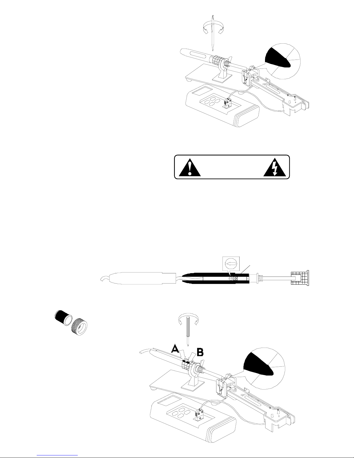
TEMPERATURE ADJUSTMENT
YOU WILL NEED THE MS412 TEMPERATURE CALIBRATION SYSTEM
TO MONITOR TEMPERATURE.
1. Loosen RC334 to expose Temp. Control Screw.
2. Using a clean and well-tinned tip do set up according to
illustration so that the thermocouple wire is hanging on
the tip.
3. Apply a small amount of solder on the Tip, just enough to
form a solder bead on top of the Tip. Place the center of
the thermocouple wire of the on top of the solder bead.
4. Again, apply a small amount of solder on the center of
the cross wire, just enough to embed the center.
5. Turn Temp. Control Screw clockwise to increase
temperature or counter-clockwise to decrease
temperature.
6. Tighten RC334.
TEMPERATURE CALIBRATION
AIR MOVEMENT WILL AFFECT THE TEMPERATURE READING.
WORK IN AN AREA WHERE THIS IS MINIMUM.
1. Use the SRW01 to pull out heater assembly, PCB & power cord from handle. Leave enough power cord slack
to install SRF20.
2. Place heater assembly, PCB & power cord inside SRF20. Install tip that is clean and well tinned.
3. With the use of the MS412 Temperature Calibration System. Follow set-up shown below.
4. Plug in tool and by using the Pot Adjustment Tool supplied, turn Temp. Control (A) to "solder-melt" temperature.
5. Apply a small amount of solder on the Tip, just enough to form a solder bead on top of the Tip. Place the
center of the thermocouple wire of the on top of the solder bead.
6. Again, apply a small amount of solder on the center of the cross wire, just enough to embed the center.
7. Turn Temp. Control (A) fully clockwise. Adjust Calibration Pot (B) until reading stabilizes at 800°F.
8. Assemble unit in original handle.
Temp. Control (A)
Calibration Pot (B)
SRF20
original handle
Tools Needed
•SRW01
•SRF20
•MS412
•Pot Adjustment Tool
Pot Adjustment Tool
SRF20
FX635
TI680 Meter
MS412 Temperature
Calibration System
SDS100
ELECTRICAL HAZARD
This test should only be done by
qualified personnel.
SRW01
Page 4

© Copyright EDSYN,Inc.1998
FORM .423
Rev E
CL1180 LONER® Soldering Instrument, 120V
Spare Parts List
1 LT375 LONER®Standard Spade Soldering Tip 1
2 RS372 Retaining Sleeve Assembly 1
3 RC334 Retaining Collar 1
4 SR081 Foam Grip, Vinyl 1
5 SR070 Heater Assy. 120V, 1
6 SR028 Power Cord 1
7 SR029 Boot, Bushing For Tool Cord 1
8 SR462 Handle, Model 920 1
9 SR032 Strain Relief, For Tool Cord 1
10 SR075 Circuit Board Assy., 120V 1
11 SR322 Spacer, Temp. Adjustment, For Control Pot 1
DESCRIPTION
PART NO.
ITEM
QTY
8
3
2
1
5
4
9
10
7
11
6
TIP CLEANING To maintain proper Tip to Ground resistance.
1. Remove Tip from Heater Assembly.
2. Using a ST707 Soldering Tool Maintenance Brush, clean Tip and
Heater Barrel at surfaces shown.
3. Install the tip and tighten RS372 Retaining Sleeve. Take note of the
gap to ensure proper fitting.
gap
clean these areas
If there is no gap, try replacing the RS372 Retaining
Sleeve.
Disassembly of this
Tool will require
the use of SRW01
Heater Removal
Tool.
15958 ARMINTA ST. VAN NUYS, CA 91406-1896
PHONE: (818) 989-2324 FAX (sales): 818-997-0895
Email: [email protected] Internet: www.edsyn.com
 Loading...