

Page 1

FA069 ATMOSCOPE
SMD Hot Air Tool
OPERATING REQUIREMENTS:
•120V, 60 Hz
®
•Regulated air ow
CAUTION: HOT AIR WILL BURN !!!
Turn off air and place tool in Pod
when not in use
HS307 Hose connect
to regulated air ow.
SPECIFICATIONS
• 120V, 70 W
• 6.5 oz. (184 g)
• Temperature range: 4000F - 8000F (2050C - 4250C)
• Temperature regulation: ±60F (±30C)
• Voltage leakage from tip to ground less than 2 MV
• Tip to ground resistance less than 2 ohm
• Complies with MIL-S-45743E, DOD-STD-2000-1B, MIL-STD-2000
WS6536E and ESD SPEC, DOD-STD-1686, DOD-HDBK-263.
• UL listed
Collar
Hot Air Tip
OPERATION
The 3 very important factors involved when working with the ATMOSCOPE SMD Hot Air Tool are amount
of air output, temperature setting and type of Tip used. The key to an effective soldering is to reow the
solder without blowing the solder across the board and thus creating bridges.
1. Have the proper Tip installed.
2. Connect Hose to regulated air source.
3. Plugged-in Tool to a power source and set
desired temperature.
4. Turn on the air and adjust pressure .
5. Direct hot air towards the connection until
solder melts. Using "SMD helpers" will make
your job easier.
CHANGING TIPS
Efciency is greatly dependent on choosing the proper tip to meet each
application.
Cut thru the connection with a
pull wire or shim blade while
hot air melts the solder.
1. Turn Tip counter-clockwise by using a WT618 Tip Wrench.
(set of 2, the other is to hold the RS321 Retaining Sleeve)
or use a WT620.
2. Remove and replace with desired Tip.
RS321
WT618
WT6 20Hot Air Tip
Page 2

REWORKING SMDs
INSTRUCTIONAL VIDEOS AVAILABLE ON 30 DAY LOAN. CALL EDSYN.
The following techniques are based on the manufacturer's point of
view and should only serve as guidelines. It's effectiveness will
depend on practice.
(RECOMMENDED FOR GULLWINGS, LEADLESS CHIP CARRIERS and QUAD I.Cs.)
METHOD 1
1. Install the proper Tip.
2. Adjust air output to 3-4 psi.
3. Set temperature to 700°F.
4. Using a WS630 SMD Pull Wire, thread the pullwire under the
leads of one side of the SMD and again thread the wire under
the leads of the opposite side.
5. Anchor one end of the Pull Wire to an unused hole of the
circuit board or maybe tape it securely to the board.
6. While directing hot air to the leads of the rst side, pull the wire
so that it will cut thru the solder connection.
7. After removing the two opposing side follow the same proce-
dure to desolder the remaining sides.
8. To resolder, use a tweezer to hold SMD in place and align
the leads with the pads.
9. Use a Fan Tip whose width is as close to the size of the SMD
Fan Tip
leads as possible.
10.Direct hot air on the leads and allow solder to reow. Release
SMD when solder solidies.
METHOD 2
(RECOMMENDED FOR LEADLESS CHIP CARRIERS)
1. Have the proper Tip installed.
2. Adjust air output to about 3-4 psi.
3. Set temperature to 700°F.
4. Heat up one corner of the SMD.
5. When the solder melts, insert the
shimblade of SMD helper under the
heated area of the chip as if cutting
thru the solder connection.
6. While directing hot air ahead of the shim
at all times, cut thru the sides of the
SMD and lift it up from the board.
7. To resolder, use a Quadra-Flow Tip.
FA069
WS630
METHOD 3
1. Use a Dual Flow Tip whose width comes closes to the
width of the SMD component leads.
2. Adjust temperature to about 750°F.
3. Adjust air output at around 3-5 psi.
4. Position Tool on top of the SMD (air is directed on both
sides of the connection) and move back and forth, until
solder melts.
5. Lift SMD off the board by using a pair of tweezers.
6. To resolder, use a tweezer to hold SMD in place and
align leads with the pad.
7. Direct hot air to the leads and reow the solder.
Release SMD when solder solidies.
Dual-Flow Tip
Page 3

SMD Hot Air Quadra-Flow Tips
ALWAYS USE PD529 or PD529A TOOL PODS
Fra cti ona l dim ens io ns are a ppr ox.
PART NO.
( in.)
A x B
( mm )
FITS PACKAGE
(for reference only)
LT494 .45 x 1.05 11.4 x 26.7 SO J- 40
2 9/6 4 x 1 3/ 64
LT482 .47 x .58 11.9 x 14.6 LC CC -3 2R
1 5/3 2 x 3 7/6 4
LT472S .48 x .48 12.2 x 12.2
3 1/6 4 x 3 1/6 4
LT472 .49 x .49 12.4 x 12.4 LC CC -2 8
1/2 x 1/ 2
LT456 .50 x .50 12.7 x 12.7 PLCC-28
1/2 x 1/2
LT485 .52 x .64 13.2 x 16.2
3 3/6 4 x 4 4/6 4
LT463 .60 x .60 15.2 x 15.2
39/64 x 39/ 64
LT468** .66 x .90 16.8 x 22.9 QFP-100
2 1/3 2 x 2 9/3 2
LT458** .70 x .70 17.8 x 17.8 PLCC44
4 5/6 4 x 4 5/6 4 LCCC-44
LT491** .71 x .94 18.0 x 23.9
2 3/3 2 x 1 5/1 6
LT477** .75 x 1.00 19.0 x 25.4 LCCC-84
1 /4 x 1
LT459** .80 x .80 20.3 x 20.3 PLCC-52
51/64 x 51/ 64
LT459-1 Slo tt ed C or ne rs ( slo t siz e: 0.125 x 200 d ept h)
LT492** .85 x .85 21.6 x 21.6
5 5/6 4 x 5 5/6 4
§
LT460** 1.0 x 1.0 25.4 x 25.4 PLCC-6 8
1 x 1
§
LT460-1 Slotted Corners
§
LT488** 1.17 x 1.17 29.7 x 29.7 QFP-144
111/6 4 x 111/6 4
*RN432 no t re qu ir ed i n Application set up
**Comes w / RN 43 3
§ M ay n ee d to p re he at P CB w it h ho t pl at es .
Page 4
See Catalog for SMD Helpers, Pull Wires and other tools
used in aiding SMD removal and placing.
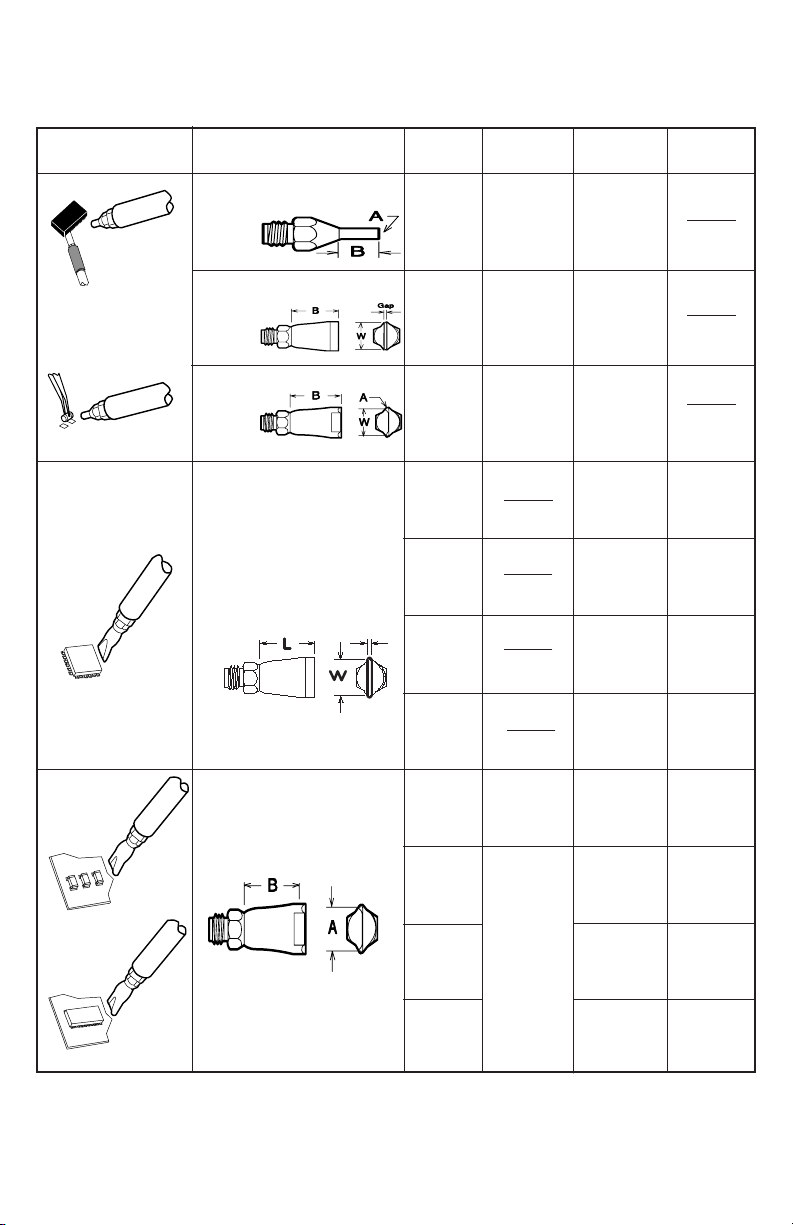
SMD Hot Air Tips
Application
Description
Jet Tip
for pin point
air ow.
Short Jet Tip
for medium
air
Turbo Flow
for large
air ow.
Part
No.
LT427
Hole Dia.
LT432
Hole Dia.
LT428
Hole Dia.
Hole
Dia.
.02 in.
1/64 in.
(0.6 mm)
.04 in.
3/64 in.
(0.9 mm)
.06 in.
1/16 in.
(1.5 mm)
L W
.38 in.
3/8 in
(9.5 mm)
.06 in.
1/16 in.
(1.5 mm)
.25 in.
1/4 in.
(6.4 mm)
Fan Tips
use a wide air flow
enough to cover
one whole side of
the S MD .
Dual Fl ow Tips blow hot
air o n bo th s id es o f th e
SMD, no t on t he S MD .
Apply AN112 or AN122
ANTI-SEIZE COMPOUND
To Heater and Area of Tip Contact.
AN122 comes in syringe dispenser.
.020 in
(.5 mm)
Hole Dia.
LT426
LT434
LT435
LT436
LT526
LT534
LT535
LT536
.03 in.
1/32 in.
(0.8 mm)
.05 in.
3/64 in.
(1.2 mm)
.30 in.
5/16 in.
(7.6mm)
.46 in.
15/32 in.
(11.7 mm)
.59 in.
19/32 in.
(14.9 mm)
.65 in.
21/32 in.
(16.5 mm)
.30 in.
5/16 in.
(7.6 mm)
.46 in.
15/32 in.
(11.7 mm)
.59 in.
19/32 in.
(14.9 mm)
.65 in.
21/32 in.
(16 .5 mm)
.17 in.
3/16 in.
(4.3 mm)
.23 in.
15/64 in.
(5.7 mm)
.35 in.
3/8 in.
(8.9 mm)
.43 in.
7/16 in.
(10.8 mm)
.12 in.
1/8 in.
(3.2 mm)
.20 in.
13/64 in.
(5.1 mm)
.28 in.
17/64 in.
(7.0 mm)
.35 in.
23/64 in.
(8.9 mm)
Page 5
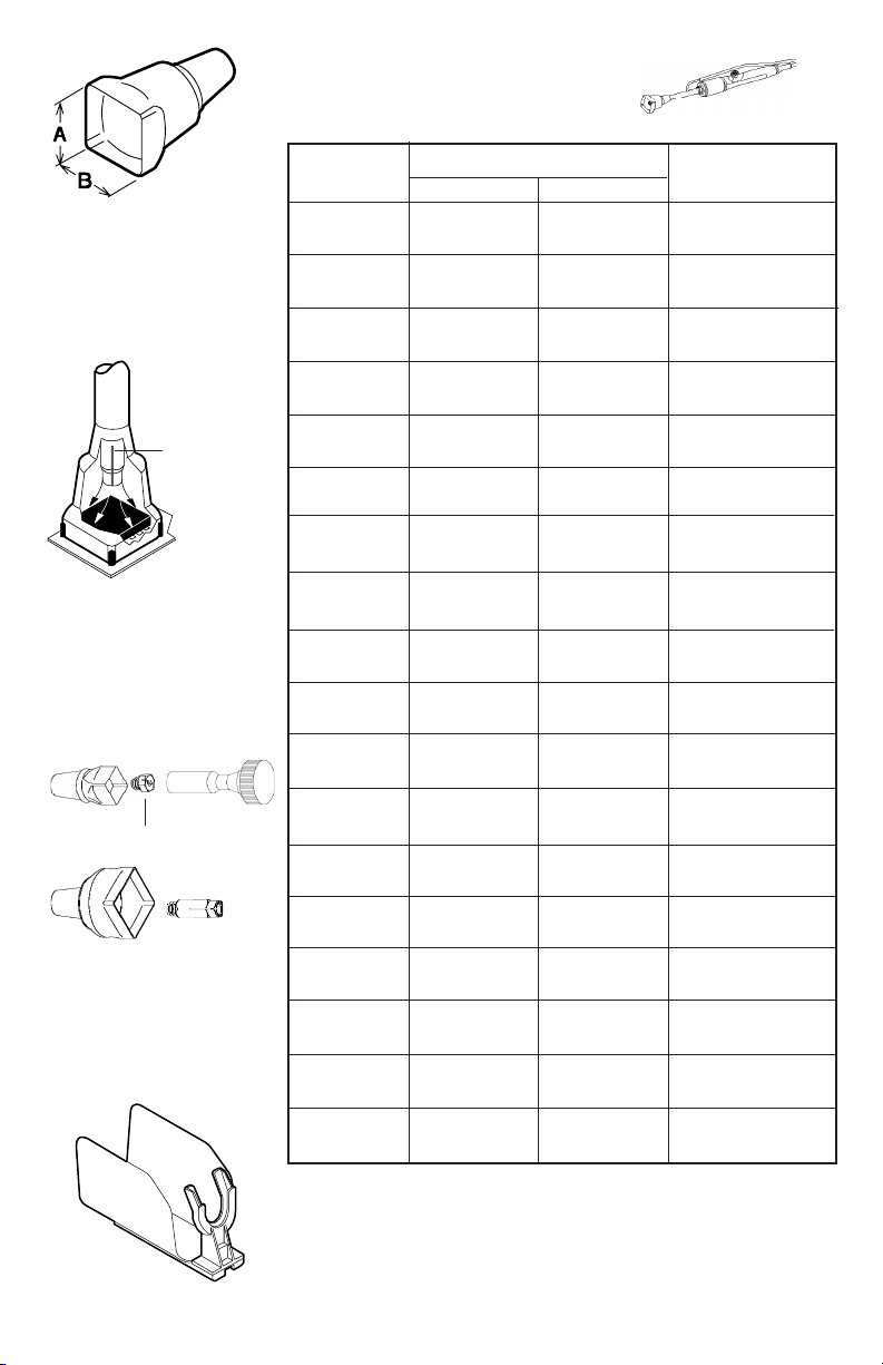
ALWAYS USE PD529 or PD529A TOOL PODS
Qua dr a- Fl ow Tips
creat e an " ov en -l ik e"
condi ti on a ro un d th e
SMD.I nc re as e ai r ou tp ut
as yo u in cr ea se t he s iz e of
the Tip.
RN433
Slott ed c or ners
(LT459-1)
Use W T6 20 Tip Wrench to
insta ll Tips with RN432 or
RN433
RN432
RN433
Use a PD529 to hold Hot
Air Tool with large QuadraFlow tips
SMD Hot Air Quadra-Flow Tips
Frac tio nal di men sio ns are app rox .
PART NO.
( in.)
A x B
( mm )
FITS PACKAGE
(for reference only)
LT448* .21 x .35 5.3 x 8.9 SO-14
7 /32 x 11/3 2
LT483* .25 x .43 6.4 x 10.9 Ceramic DIP 16
1 /4 x 7/1 6
LT489 .25 x .78 6.4 x 19.8
1 /4 x 25/ 32
LT449 .26 x .41 6.6 x 10.4 SO -1 6
1 /4 x 13/ 32
LT480 .31 x .52 7.9 x 13.2 LC CC -2 2R
5 /16 x 33 /64
LT478 .32 x .45 8.0 x 11.4 LC CC -1 8R
5 /16 x 29 /64
LT462 .34 x .55 8.7 x 13.9 PLCC-18
11/ 32 x 35/ 64
LT470* .36 x .36 9.2 x 9.2 LCCC-20
2 3/6 4 x 2 3/6 4
LT487 .36 x .60 9.1 x 15.2
2 3/6 4 x 3 9/6 4
LT452 .38 x .52 9.5 x 13.2 SO-20 L
3 /8 x 33/ 64
LT481 .38 x .58 9.5 x 14.6 LCCC-28R
3 /8 x 37/ 64
LT455 .40 x .40 10.2 x 10.2 P LC C- 20
13/32 x 13/ 32
LT486 .40 x .60 10.2 x 15.3
13/32 x 13 /64
LT484 .40 x .79 10.2 x 10.2 SO J- 20
1 3/3 2 x 5 1/6 4
LT450 .42 X .43 10.7 X 10.9 SO-16L
7/16 X 7 /16
LT454 .43 x .73 10.9 x 18.6 SO -2 8L
7 /16 x 18 .6
LT451 .44 X .48 11.2 X12.2 SO-18L
7/16 X 3 1/6 4
LT493 .45 x .85 11.3 x 21.6 SO J- 32
2 9/6 4 x 5 5/6 4
*RN432 no t re qu ir ed i n Application set up
**Comes w / RN 43 3
Page 6
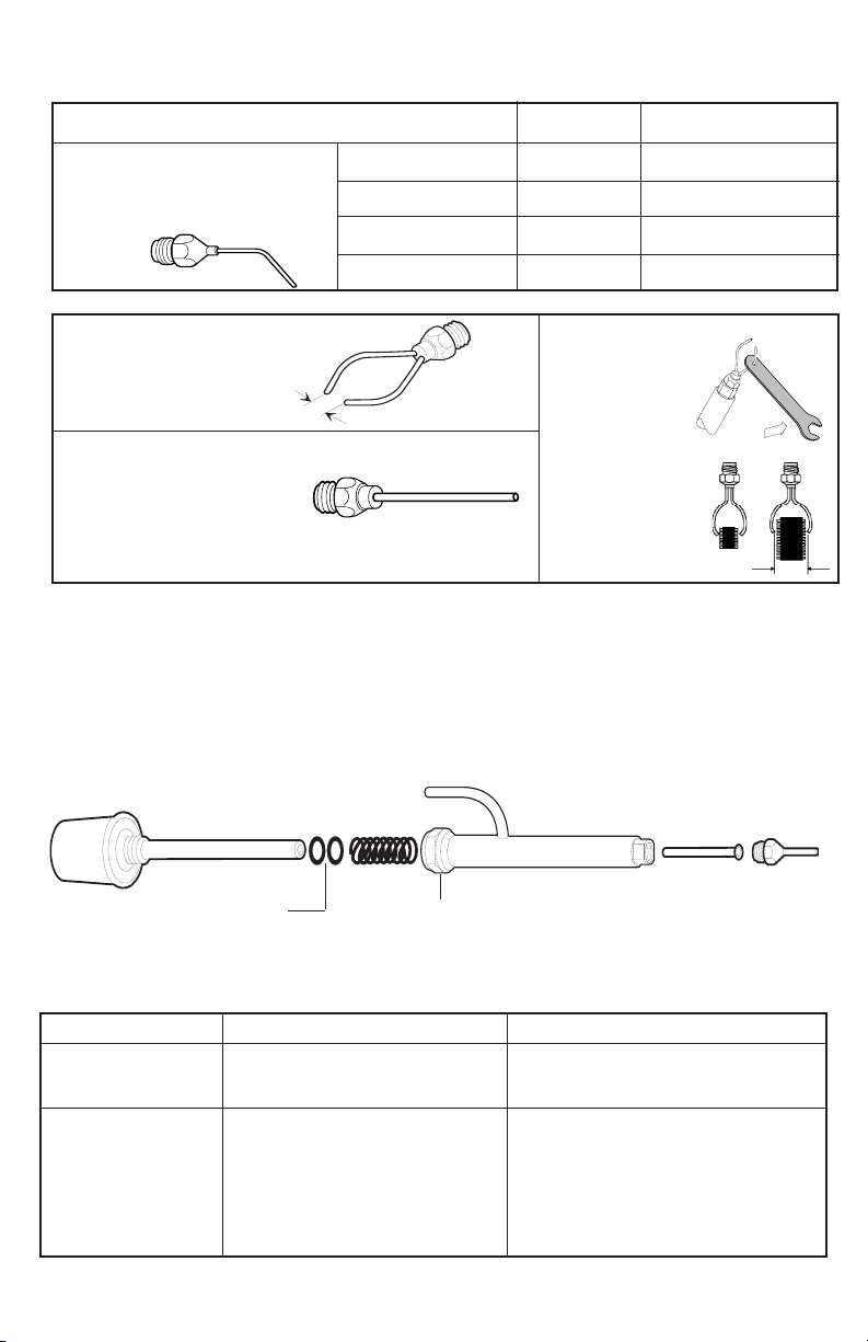
LONER® Hot Air Curl Tips
DESCRIPTION
PART NO.
Fra cti ona l dim ens io ns are a ppr ox.
NOZZLE INSIDE DIA.
HOT AIR CURL TIP For soldering
& de sol deri ng SM Ds usi ng a
curve air flow for har d to rea ch
places.
JET LT510 .023 in. 1/32 (0.6 mm)
SMALL TURBO LT511 .062 in. 1/16 (1.6mm)
MEDIUM TURBO LT512 .073 in. 5/64 (1.9 mm)
LARGE TURBO LT513 .101 in. 7/64 (2.6 mm)
LT572
"DUAL-FLOW ADJUSTABLE"
Hot Air Tip
Hole Dia.= .04 (1.0 mm)
Up to 1.25 (31.8 mm)
LT571
"LONG-FLOW BENDABLE"
Hot Air Tip
Hole Dia.= .04 (1.0 mm)
Nozzle Length= 1.10 (27.9 mm)
TOOL MAINTENANCE
• Replace cracked Hose.
• Make sure HT495 Hot Tube is not clogged.
• Replace worn-out OS139 O-rings.
WT622(optional)
With a Bending Tool
the Nozzles of
Dual Flow
Adjustable
& Long
Flow Bendable Tips
can be adjusted to
direct hot air to
accomodate
most SMD sizes.
Heater
OS139
CC355
retaining nut
RS321
TROUBLESHOOTING
Symptom Cause Remedy
Tool does not heat
up.
Weak or no air output.
a) Open Heater element.
a) Leak along the air lines and
O-rings inside Heater assembly.
b) Clogged RS321 or clogged
Tip.
c) Dirty CC355 Chamber Coil.
a) Send to Factory.
a) Make sure all connections are prop-
erly installed. Replace cracked hoses
and O-rings.
b) Clean Air passages in the RS321 and
Tip.
c) Clean CC355.
HT495 Hot Air Tip
Page 7
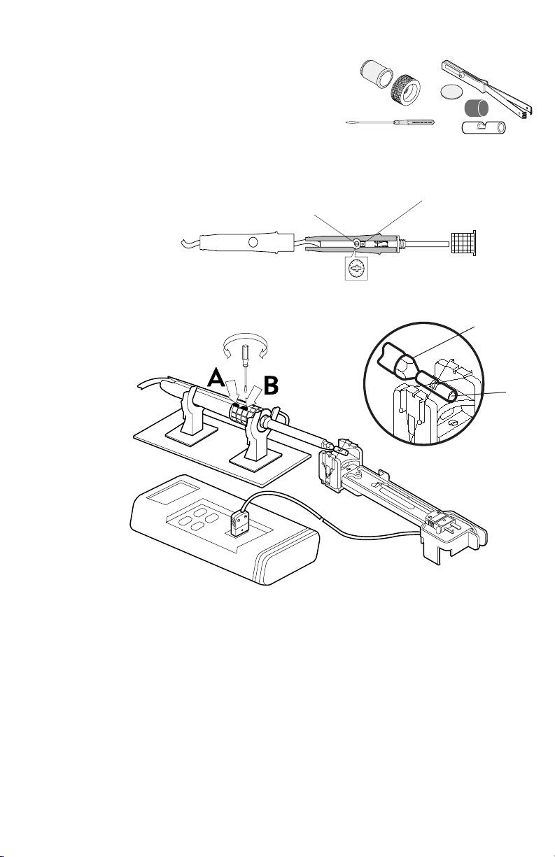
TEMPERATURE CALIBRATION
1. Use the DS299S to remove the temperature
control knob. Remove RS321 sleeve. Turn
temp. control (A) so arrow points to cord.
2. Use the SRW01 to pull out heater assembly,
PCB & power cord from handle. Leave
enough power cord slack to install SRF30.
3. Place heater assembly, PCB & power cord
inside SRF30. Install RS321 and connect to
air source.
Items Needed
• SRW01
• DS299S
• SRF30
• MS412
• TPL09-1
• SD418
SRW01 DS299S
SD418 TPL09-1
original handle
4. Follow set-up shown using of the MS412
Temperature Calibration System. Includes:
•TI680
•SDS100
•FX635
FX635
Temp. Control (A)
TI680
SRF30
Calibration Pot (B)
Hot Air Tip
SDS100
TPL09-1
Ceramic
Locator
5. Insert the hot air tip inside the TPL09-1,
place the center of the thermocouple wire of
the SDS100 inside the slot of TPL09-1 locator. Use only CLEAN thermocouple wires.
6. Turn on air, adjust to 5 scfh airow.
7. Turn temp. control (A) fully clockwise. Adjust
calibration pot (B) until reading stabilizes at
850°F.
8. Assemble unit in original handle.
Page 8
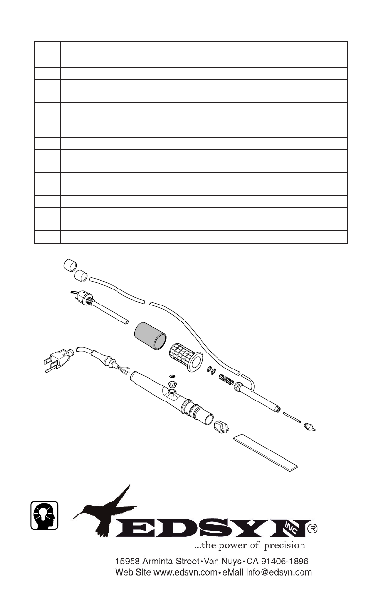
FA069 ATMOSCOPE® SMD HOT AIR TOOL
SPARE PARTS LIST
ITEM
NO.
PART NO.
DESCRIPTION
1 HS307 Hose, Low Static Silicone (Sold Per Foot) 5 ft.
2 SR102 120 V Hollow Heater Assembly for FA069 1
3 SR081 Vinyl Finger Grip 1
4 RC349 Threaded Retaining Collar 1
5 OS139 O-Ring, Silicone, for FA069 (Set of 2) 1 set
6 CC355 Chamber Coil for FA069 Hot Air Tool 1
7 RS321 Retaining Sleeve for FA069 Hot Air Tool 1
8 HT495 Hot Tube for FA069 Hot Air Tool 1
9 LT428 LONER® S.M.D. Hot Air Turbo Flow Tip 1
10 SR028 Power Cord, 3-Prong, 120 VAC 1
11 SR029 Boot for Power Cord 1
12 SR030 Clear Handle for Model 930 1
13 SR031 Knob, Temperature Control for Clear Handle 1
14 SR111 Logo, 3/8" Dia. Aluminum, Self Adhesive 1
15 SR032 Cord Strain Relief 1
16 SR033 Circuit Board, Model 930 1
QTY
REQ'D
2
10
Intellectual
Property
© Copyright EDSYN Inc. 2002
11
1
3
4
14
12
13
5
6
7
8
9
15
16
FA069i.pdf
Form.609 Rev D
 Loading...