


951SX
LONER®
Temperature Controlled
Soldering Station
• COMPLIES WITH MIL-S-45743E, MIL-STD-2000-1B, WS6536E AND
ESD SPEC, DOD-STD-1686, DOD-HDBK-263
• UL listed
Instruction manual
made
in
U S A

Specications for Model 951SX
Power Requirements 120V, 60 Hz
Power Rating 15W - 220W
Heater Rating 120V, 95W
Temperature Range 400°F-800°F/205°C-427°C
Temperature Regulation ±6°F/±3°C
Tip-to-Ground Voltage
Leakage/Resistance < 2mV/< 2 ohms
Overall Dimension 4.1"W x 8.2"H x 10"D
104 mm x 208 mm x 254 mm
Weight 2.5 lbs/1.1 kg
Contents
951SX includes 1 - LT375 Soldering Tip
PD528 Tool Pod
SH230 Sponge Holder
(Includes RS199 Cleaning Sponge,
RS243 Leveling Pad, LN230 Liner)
WP556 WIGAPRY Low Static Computer Aid

Static Safe
Temp.
Regulation
Indicator
Power Switch
SH230
Sponge Holder
PD528 Tool
Pod
Calibration Pots for HI & LO Temp.
Hollow Threadless Heater
WARNING:
DO NOT HIT OR TAP THE SOLDERING TOOL. THE HEATER ELEMENT WILL BREAK!!!
MAINTENANCE
• Replace RS199 Cleaning Sponge
1. Fill water only up to the top of the RS243
Leveling Pad.
2. Depress RS199 to moisten it completely.
RS199
RS243
LN230
SH230-1
CAUTION:
Over-lling can cause thermal shock
to the tip or heating element during
tip cleaning.
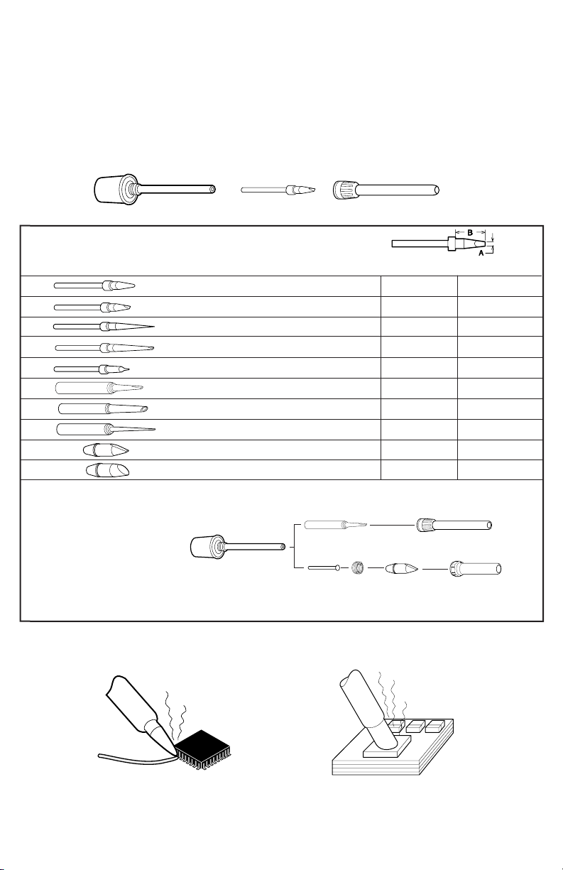
• Replace SC581 Solder Collector
1. Hold the Housing rm and turn Cap
counter-clockwise and pull it away from the
Housing.
2. Remove used SC581 and replace with
a new one.
3. Reassemble Pod with TOP of the Cap in
proper position.
SR042
Thermal
Housing
SC581
Solder Col-
lector
SR043
Front Hous-
ing

TIP CLEANING
To maintain proper Tip to Ground resistance.
1. Remove Tip from Heater Assembly.
2. Using a ST707 Soldering Tool Maintenance Brush, clean Tip and Heater Barrel
at surfaces shown.
3. Install the tip and tighten RS372 Retaining Sleeve. Take note of the gap to ensure
proper tting.
clean these areas
ST707
gap
TIP CARE
1. Set desired temperature. Blinking Neon Lamp means Tool is ready.
2. TIN the Tip. (apply solder)
3. Do not rub, bend or reshape the Tip.
4. Always clean the Tip by wiping it against the saturated sponge and always RE-TIN.
TEMPERATURE CALIBRATION
1. Turn on power and set Temperature Control Knob to 400°F (205°C).
2. Using a clean and well tinned Tip, apply a small amount of solder on the Tip, just enough
to form a bead on top of the Tip.
3. Place the center of the thermocouple wire of the SDS100 on top of the bead.
4. Again, apply a small amount of solder on the center of the thermo-couple wire, just enough
to embed the center.
5. Adjust LO-Temp. Calibration Pot so the Meter will read 400°F (205°C).
6. Set Temperature Control Knob to 800°F (427°C).
7. Adjust Hi-Temp. Calibration Pot so the Meter will read 800°F (427°C).
MS412
TemperatureCalibration System
FX635
METER
SDS100
CHANGING TIP
DO NOT USE the soldering tool if soldering tip is loose. This will cause the heater element to break.
1. MAKE SURE YOUR TOOL IS COOL!
2. Turn Retaining Sleeve counter-clockwise to remove.
3. Remove old Soldering Tip.
4. Insert new Tip.
5. Install Retaining Sleeve. (should be "nger" tight only.)
Retaining Sleeve
Soldering Tip
Iron Plated for long life•Nickel and Chrome Plated for optimum heat transfer
SOLDERING TIPS
CONTACT EDSYN FOR MORE SELECTIONS
LT374 Standard Probe
LT375 Standard Spade
LT392 Extra-Long Needle Point
LT394 Extra-Long Spade
LT446 SMD Probe
LT337BC Heavy Duty Terminal Spade
LT223BC Heavy Duty Fine Spade
LT222BC Extra long Needle Point
LT153BH Jumbo Spade
LT155BH Jumbo Angle Spade
SET-UP & REQUIRED ACCESSORIES FOR HEAVY DUTY AND JUMBO TIPS
Apply
AN112 or AN122* Anti-Seize
Compound
to Heater and area of Tip contact.
RS372- for General Purpose Tip
RS271- for Heavy Duty Tip
"BC"
HEAVY DUTY TIP
AC735
A
.03 (0.8 mm) .48 (12.2 mm)
.06 (1.5 mm) .48 (12.2 mm)
.02 (0.5 mm) 1.13 (28.8 mm)
.07 (2.0 mm) .93 (23.6 mm)
.03 (0.8 mm) .48 (12.2 mm)
.10 (2.5 mm) .74 (18.8 mm)
.06 (1.5 mm) 1.21 (30.7 mm)
.04 (1.0 mm) 1.21 (30.7 mm)
.20 (4.9 mm) .93 (23.6 mm)
.32 (8.3 mm) .97 (21.1 mm)
RS271
JUMBO
TIP
RS351
B
*AN122 Anti-Seize Compound comes in syringe dispenser.
Fine point tip for
SMD soldering.
Large and heavy tip for
heavy duty soldering.
1A
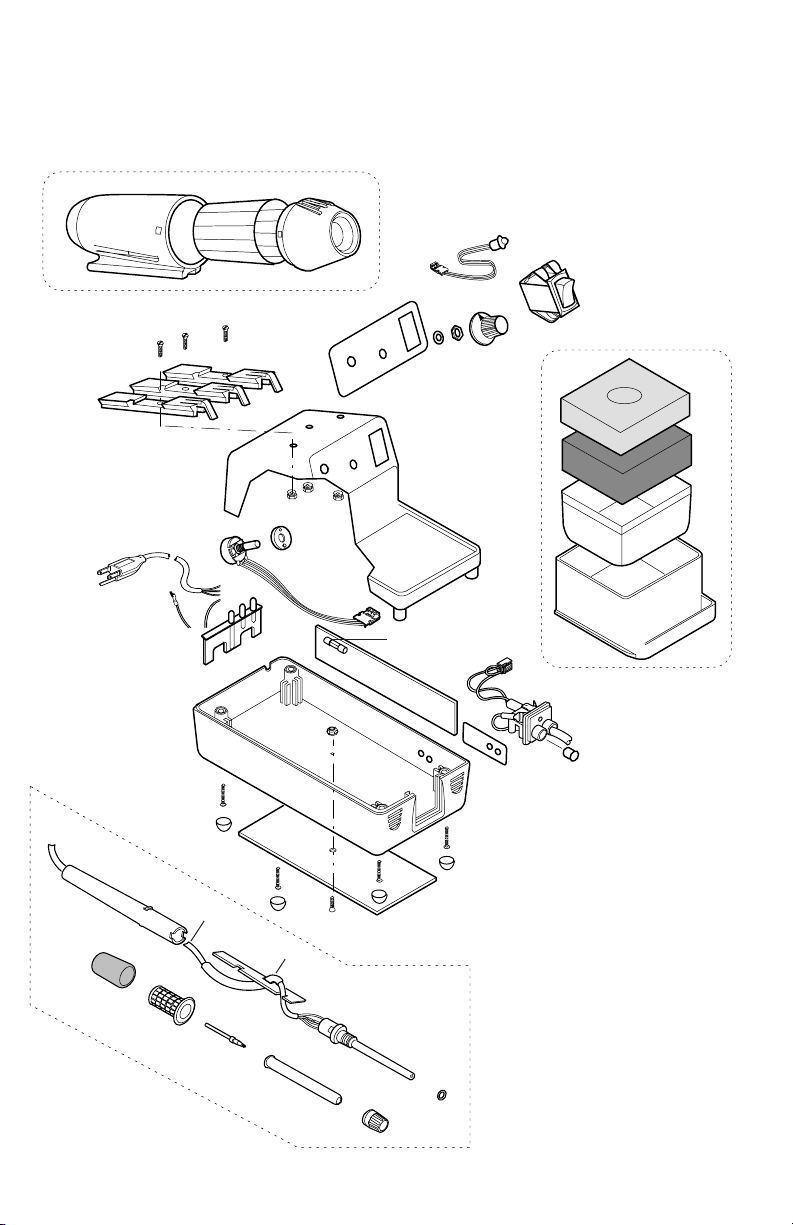
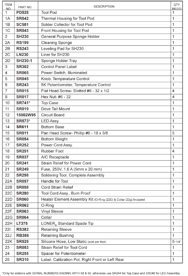
951SX LONER® SOLDERING STATION
SPARE PARTS LIST
1
13
1B
1C
4
11
22A
17
7
5
3
10
9
24
6
20
9
14
21
12
23
15
18
25
19
23
2
2A
2B
2C
2D
22F
22G
22C
22H
22B
22I
7
16
22
22D
22E
22J
SR611

951SX instruction manual
NO PART OF THIS PUBLICATION INCLUDING THE INDIVIDUAL ICONS
MAY BE REPRODUCED OR UTILIZED IN ANY FORM OR BY ANY MEANS
THE NAMES LONER, SOLDAPULLT, SOLDAVAC, ATMOSCOPE
AUTO-VAC, IDLE-REST, PIXTER, FUMINATOR, OCTAVAC AND KLATCH
Intellectual
Property
TIP STYLE ON SOLDERING, DESOLDERING AND HOT AIR TOOLS MAY VARY.
WITHOUT THE PERMISSION OF EDSYN, INC.
ARE REGISTERED TRADEMARKS OF EDSYN, INC.
MOST PRODUCTS ARE COVERED BY U.S. AND
FOREIGN PATENTS AND PENDING APPLICATIONS.
SUBJECT TO CHANGE WITHOUT NOTICE.
ALL RIGHTS RESERVED.
DESIGN, COLOR AND MATERIALS
PRINTED IN U.S.A.
©Copyright EDSYN, Inc. 2002
951SXi .pdf
FORM.655 Rev G
 Loading...