

Edson 165AL-30, 165AL-30-200 Operations & Parts Manual
P-165AL-30-07 pg. 1
Operation & Parts Manual
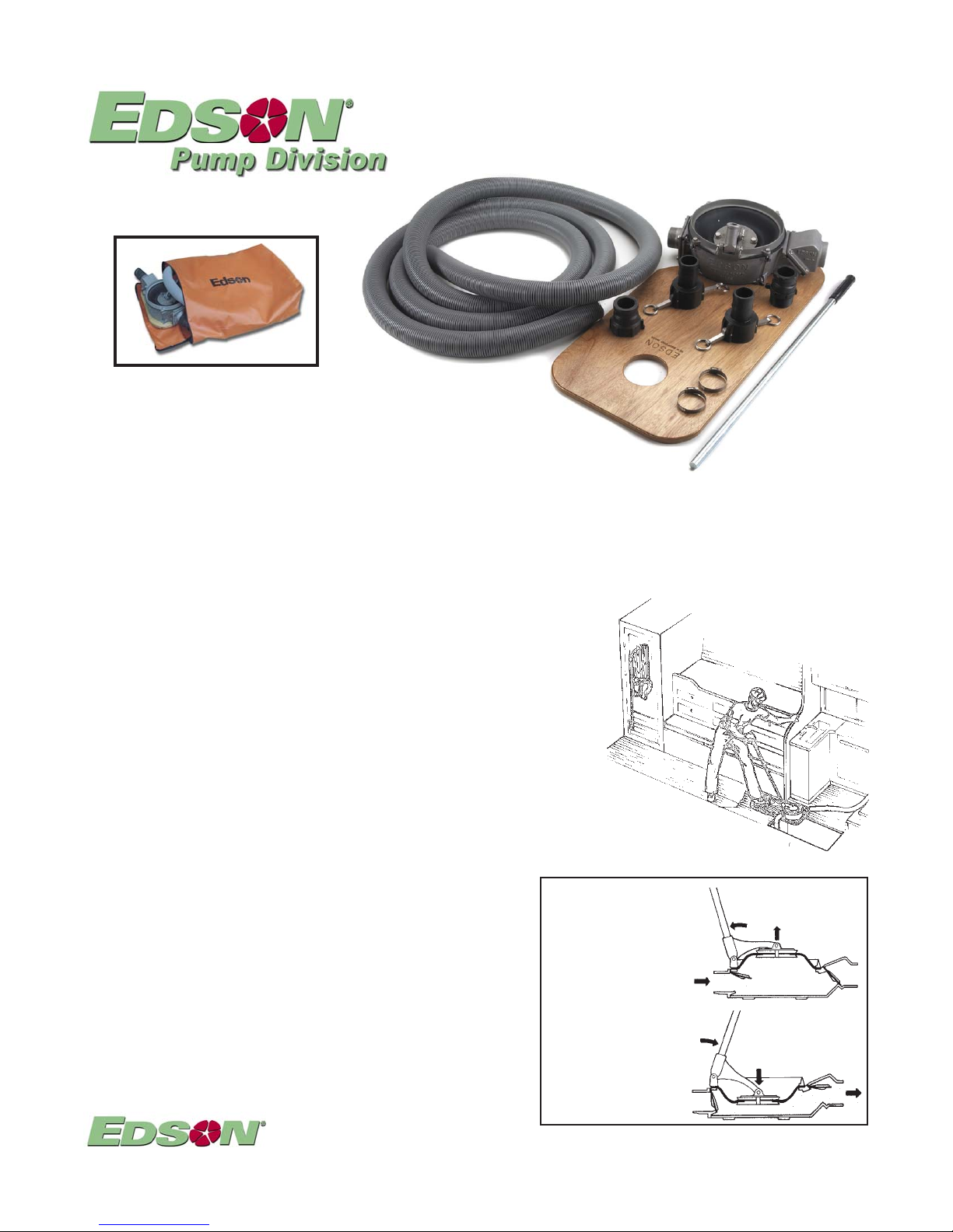
MODEL 165AL-30 PORTABLE PUMP KIT
Optional Carrying and Storage Bag
Set Up
Order # 275-31
165AL-30-200
1. Screw the 2 male quick clamp adapters onto the pump. Threads must be sealed with pipe sealer.
2. Determine the length of the inlet and discharge hose and cut them from the single length supplied with the kit. Use a hack
saw to cut through the hose. If the primary use is for on board a boat, place the pump and the board where you want to do
the pumping. Stretch the hose from the bottom of the boat, across the pump to the place you want the discharge to end up.
Cut the hose where it crosses the pump.
3. Install the two female hose couplings into one end of each hose section. Secure them with the hose clamps.
4. Clamp the female couplings to the male adapters.
5. Check the bolts holding the pump to the carrying board.
6. Test the installation with clean water and check for leaks.
Operation
1.Stand on the open end of the carrying board. Use your body weight to stabilize the
pump and board. Grip the handle with one or both hands and pull the handle back
to raise the diaphragm for the suction stroke. Push forward from the same position
for the discharge stroke.
2.The raising of the diaphragm creates a vacuum that pulls the discharge valve
assembly closed.
3.Atmospheric pressure pushes liquid and /or air up the inlet hose to fill the vacuum.
4.Pushing forward on the handle compresses the air and liquid under the diaphragm.
5.The pressure closes the inlet valve assembly preventing the liquid trapped in the inlet
hose from dropping back to atmosphere.
6. The air and liquid under the pressure of the diaphragm are forced out through the discharge.
Performance & Specifications
Static Head: Suction-15 ft / 4.57m Discharge-15 ft / 4.57m
Dry Suction Lift: 12ft / 3.65m
Volume: 1 Gallon Per Stroke at 5 ft Suction Lift and 0 Discharge
Total Volume depends on the pumping speed and the conditions when punping.
A Cycle is one complete raising and lowering of the diaphragm. Static Head is
determined by the vertical height, length and size of the plumbing and the viscosity
of the liquid. For most manual pump applications just measure the vertical
distance between the liquid being pumped and the inlet of the pump. If it is within
15ft. then you should be able to pump the liquid. See Installation Guidelines for
other considerations.
146 Duchaine Blvd., New Bedford, MA 02745-1292 Tel. 508-995-9711 Fax 508-995-5021 E-Mail pumps@edsonintl.com
Suction Stroke
Inlet Valve Assembly:opens
into the pump
Discharge Valve Assembly:
closes and seals on the valve
seat that is part of the pump
base under the discharge
chamber.
Discharge Stroke
Discharge Valve Assembly:
opens away from the pump
Inlet Valve Assembly:closes
and seals on the valve seat
that is part of the inlet
chamber.
Page 1 Installation & Operation
Fig. 4
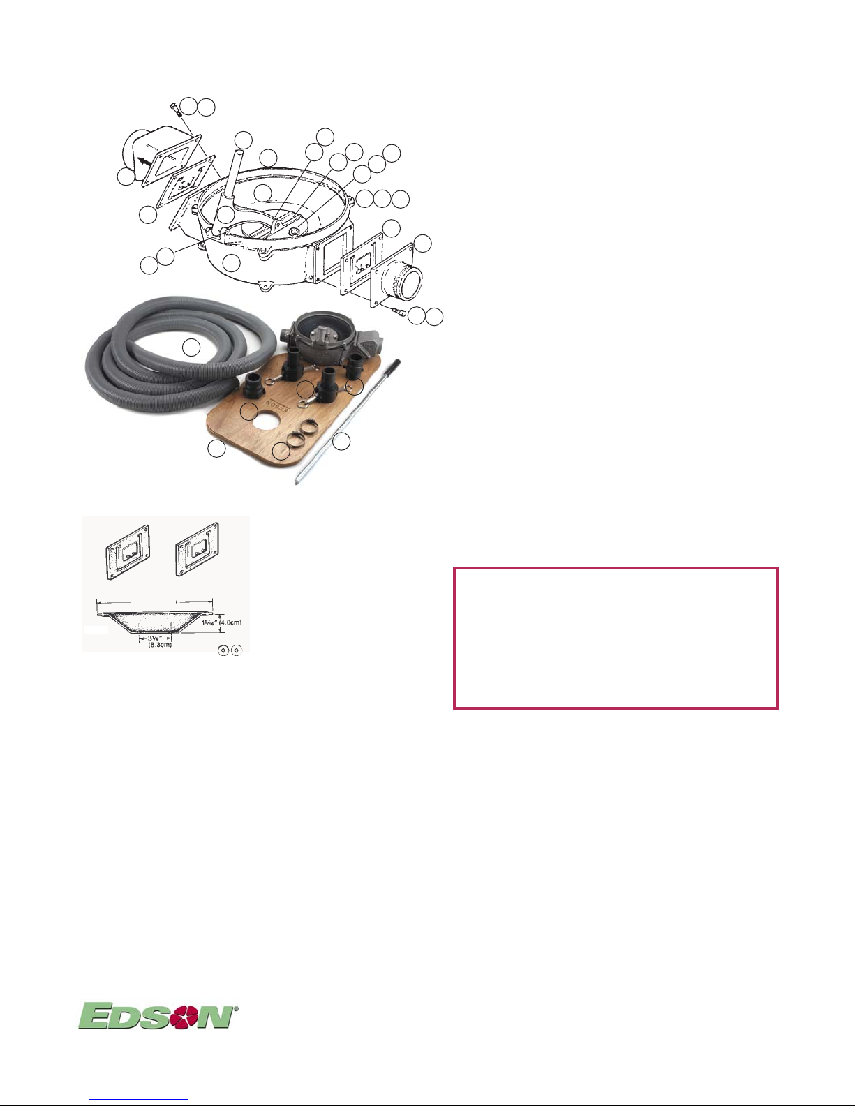
Parts
1
A-1200
4
2
13
20
Pump Spares Kits:
113
G-107
Size 0
10.5"
G-107
13H-0
17
23
15
22
11
7
1
8
6
25
26
24
Side Inlet Nitrile Pump Spares Kit
Order # 114N-117-120 Includes:
113N-0 Size 0 Diaphragm - Nitrile
160-G-107 Valve Assembly - Nitrile (2)
160-A-1200 3/8" Sealing Washer - Stainless (2)
Side Inlet Hypalon Pump Spares Kit
Order # 114H-117-120 Includes:
113H-0 Size 0 Diaphragm - Hypalon
160-G-107 Valve Assembly - Nitrile (2)
160-A-1200 3/8" Sealing Washer - Stainless (2)
Side Inlet Viton Pump Spares Kit
Order # 1 14V- 117-120 Includes:
113V -0 Size 0 Diaphragm -Viton
160-G-107V Valve Assembly - Viton (2)
160-A-1200 3/8" Sealing Washer - Stainless (2)
12
20
P-165AL-30-07 pg. 2
165AL-30-200 Parts:
Key # Part No. Description Qty
1 113N-0 Size 0 Diaphragm - Nitrile 1
2 160-G-107 V alve Assembly 1
3 160-A-1200 3/8" Sealing Washer - Stainless 2
10
3
14
18
15
19
16
9
2
5
17
15
27
4 160-B-50A-200 2" Discharge Chamber- Alum. 1
5 160-B-68A 2" Suction Chamber - Alum. 1
6 160-C-186 Side Inlet Pump Base - Alum. 1
7 160-C-4A Headring Alum. 1
8 160-B-28A Drive Arm -Alum. 1
9 160-A-1A Upper Standard - Alum. 1
10 160-A-906 Lower Standard-SS (not visible in drawing) 1
1 1 160-A-41ST 32" Pump Handle with Grip 1
12 960-A-1315C Head Ring Pivot Pin 1
13 960-A-1315E Standard Pivot Pin 1
14 F1/4-1.75-SC 1/4-20 X 1.75 Socket Head Cap Srew Stainless 4
15 F1/4-FN 1/4-20 Nut Stainless 12
16 F1/4-LW 1/4" Lock Washer 4
17 F1/4-1-SC 1/4-20 X 1" Socket Head Cap Screw Stainless 8
18 F3/8-LW 3/8" Lock Washer 2
19 F3/8-1-HH 3/8-16X1" HHCS Stainless 2
20 1/8" X 3/4" Cotter Pin Stainless 4
21 1/4"-20 X 1.5" Carriage Bolts (Not Shown) 4
22 1 16CB-31 Pump Carry Board 1
23 671FH-200 Flex Hose 2” 20’
24 670ST-200 Hose Clamps 2” Stainless 2
25 156FE-200NY Quick Clamp Hose Coupling, Female 2” 2
26 158MF-200NY Quick Clamp Adapter Male QC X FNPT 2” 1
27 157MM-200NY Quick Clamp Adapter Male QC X MNPT 2” 1
165AL-30-150 Parts: same as above except for the following:
Key # Part No. Description Qty
4 160-B-50A-150 1 1/2" Discharge Chamber- Alum. 1
11
5 160-B-324A 1 1/2" Suction Chamber - Alum. 1
23 671FH-150 Flex Hose 1 1/2” 20’
24 670ST-150 Hose Clamps 1 1/2” Stainless 2
25 156FE-150NY Quick Clamp Hose Coupling, Female 1 1/2” 2
26 158MF-150NY Quick Clamp Adapter Male QC X FNPT 1 1/2” 1
27 157MM-150NY Quick Clamp Adapter Male QC X MNPT 1 1/2” 1
Optional Parts substituted upon request:
1 113H-0 Size 0 Diaphragm - Hypalon 1
1 1 1 3V - 0 Size 0 Diaphragm - Viton 1
2 160-G-107V Pump Valve Assembly - Viton 1
CAUTION
Special Applications - Edson pumps are used for many
diverse applications. Some may require special parts or
maintenance procedure. i.e.. pumping liquid with gasoline
or other fuels requires using Viton diaphragms and valves.
If you have any questions regarding procedures for your
application, call Edson customer service.
Maintenance & Trouble Shooting
PUMPS USED FOR CRITICAL APPLICATIONS SHOULD BE INSPECTED AND TESTED OFTEN
V isually Inspect Pump Inside and Out for Corrosion and Wear. Oil pivot pins. Replace Parts as Required.
Pump Performance Depends On an air tight diaphragm, valve assemblies that seal well on the pump inlet and discharge
valve seats and inlet plumbing that is air tight all the way to the point it is submerse in the liquid. If the pump is not pumping
check first for anything blocking the hose. If it is clear then check the pump by:
1. Removing all hose and fittings from the pump.
2. To check the discharge valve assembly and diaphragm put your hand tightly over the pump inlet and pull back on the
handle. You should feel a vacuum suction and if the discharge valve assembly and diaphragm are working properly, you
should not be able to raise thediaphragm all the way. If you do not feel any suction, do the same thing again and listen for
air being sucked in around the diaphragm. If you hear air movement, inspect for loose bolts or warn diaphragm. If you
hear no air movement, remove the discharge chamber and inspect the valve assembly and valve seat. Clean or replace
the valve and clean or resurface the valve seat as appropriate.
3. To check the inlet valve assembly raise the diaphragm; put your hand over the discharge and push forward on the
handle. If the inlet valve is sealing properly, you should feel the pressure against your hand. If you don't, then remove the
inlet chamber and inspect the valve assembly and valve seat. Clean or replace the valve and clean or resurface the
valve seat as appropriate.
4. When you are sure the pump is working properly and the pump still will not pump liquid, check the inlet plumbing for
leaks. Depending on the height above the liquid even one unsealed fitting can prevent liquid from getting to the pump.
146 Duchaine Blvd., New Bedford, MA 02745-1292 Tel. 508-995-9711 Fax 508-995-5021 E-Mail pumps@edsonintl.com
Page 2 Parts, Maintenance & T rouble Shooting
 Loading...