

Page 1
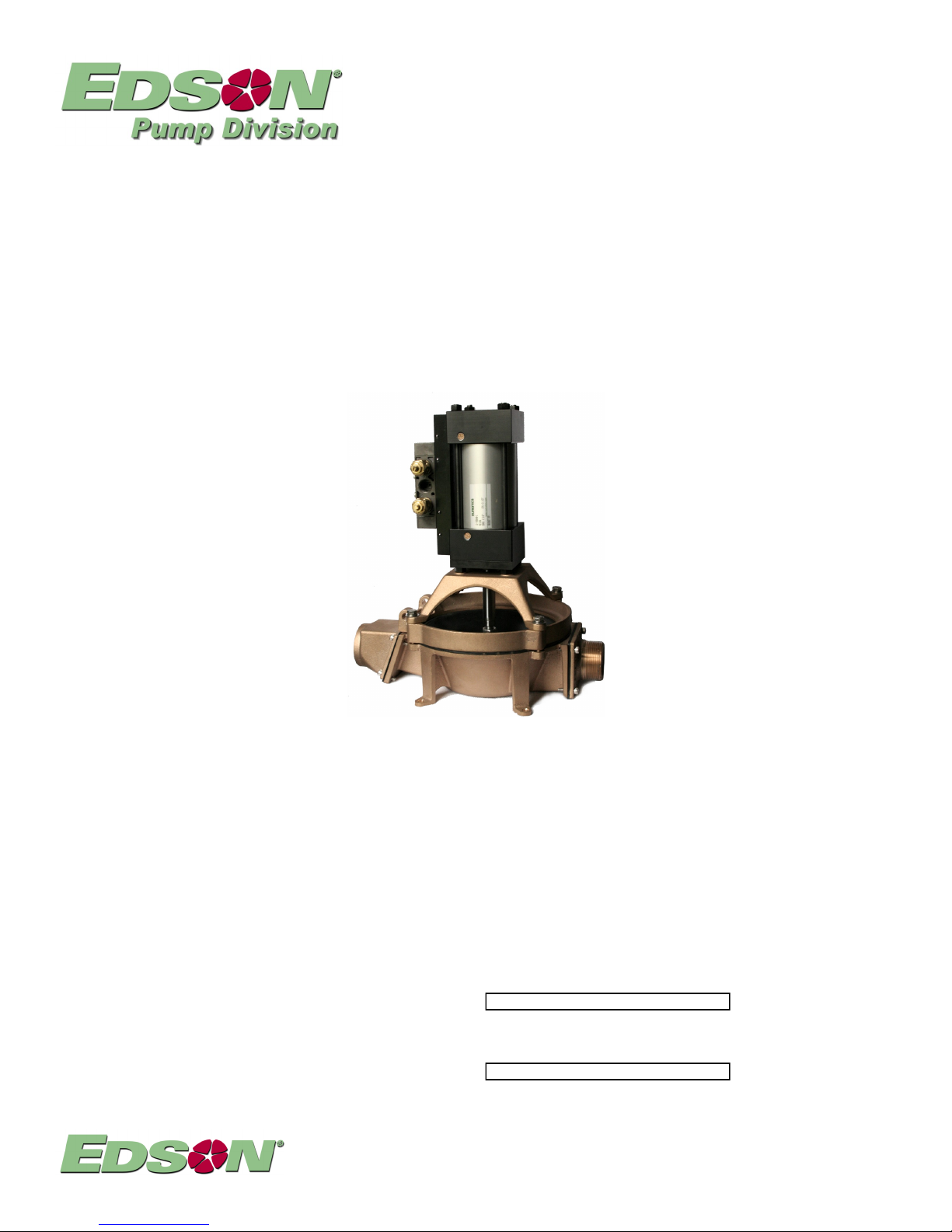
Model 220A
Installation and Operations Manual
Page 1 Index
Page 2 Performance & Dimensions
Page 3 Installation Guidelines
Page 6 Operations Guidelines
Page 8 Maintenance & Repair
Page 9 Trouble Shooting
Page10 Parts
P-220A-2012-04
220ACA-150 Air Powered Diaphragm Base Mount Aluminum 1 1/2” Inlet and 1 1/2” Discharge
220ACB-150 Air Powered Diaphragm Base Mount Bronze 1 1/2” Inlet and 1 1/2” Discharge
Make sure the pump received is the pump ordered. Compare the pump with the packing list.
Make sure the parts list attached to this manual is the one for your pump.
Fill in the Serial No. and Model No.below
ENTER YOUR PUMP DATA HERE
SYSTEM SERIAL #
From Edson Serial # Sticker On Pump Frame
PUMP MODEL #
From Packing List i.e.. 220ACB-150
146 Duchaine Blvd., New Bedford, MA 02745-1292 Tel. 508-995-9711 Fax 508-995-5021 E-Mail pumps@edsonintl.com
Page 2
Performance & Specifications
Pump Performance Is Dependent On Cycle Rate of The Pump Air Cylinder & The Plumbing Head.
l Volume is expressed in GPM (gallons per minute) and LPM (liters per minute)
l A Cycle Rate is one up and down stroke of the cylinder. Maximum cycles rate for this pump
should not exceed 60 per minute. Over 60 cycles per minute the pump begins to cavitate.
l Head conditions are determined by the height, length and size of the installation plumbing
connected to the inlet and discharge of the pump base.
General Performance Specifications:
l Static Head: Suction 20 ft / 6.1m Discharge 18 ft / 5.47m (1 1/2" Hose or Pipe)
l Dry Suction Lift: 17 ft / 5.18m (1 1/2"ID Pipe or Hose)
l Continuous Duty Discharge Heads: Should be Limited to 10 ft. / 3m
l Performance: 20 GPM / 75.7LPM at 5 ft Suction Lift and 0 Discharge at
60 Cycles per Min. w/ 1 1/2" Pipe
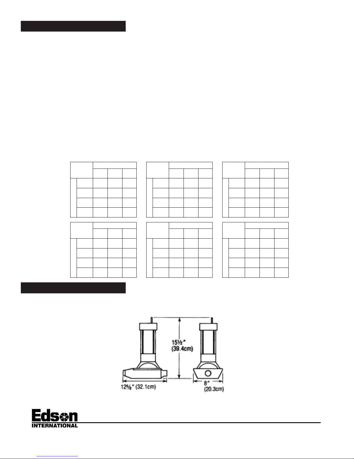
Volume Charts:
l Use the following charts as guides to determine the performance volume at different cycle rates
with the pump installed with a variety of suction and discharge plumbing conditions.
P-220A-03
Dimensions
AT 56
Cycles
Per Min.
S
U
C
T
I
O
1 .5 meters
N
H
E
I
G
H
4 .2 meters
T
AT 30
Cycles
Per Min.
S
U
C
T
I
O
1 .5 meters
N
H
E
I
G
H
4 .2 meters
T
D I S C H A R G E H E I GH T
1 foot
18 gpm
.3 meters
68.4 lp m
17.5 gpm
5 feet
66.5 lpm
10 f eet
16.5 gpm
3 meters
62.7 lpm
6 gpm
17 f eet
22.8 lp m
D I S C H A R G E H E I GH T
1 foot
7 gpm
.3 meters
26.5 lp m
6 gpm
5 feet
22 .8 lp m
10 f eet
5.5 gpm
3 meters
21 lpm
5 gp m
17 f eet
19 lp m
220ACA-150
220ACB-150
1 foot
5 feet
10 f eet
17 f eet
1 foot
5 feet
10 f eet
17 f eet
12.9 gpm
49 lpm
12.5 gpm
47.5 lp m
11.8 gpm
44.8 lp m
5 gp m
4.6 gpm
17.5 lp m
4 gpm
15.2 lp m
3.6 gpm
13 .7 lp m
3.3 gpm
12 .5 lp m
D I S C H A R G E H E I GH T
5 feet
1.5 mete rs
12 .1 g pm
46 lpm
12 .1 g pm
10.7 gpm
40.7 lp m
4 gpm
15 lp m
5 feet
1.5 mete rs
4 gpm
3.6 gpm
13.7 lp m
3.3 gpm
12.5 lp m
2.7 gpm
10 lpm
10 f eet
3 meters
12 .1 g pm
46 lpm
11 g pm
41 .8 lp m
9.6 gpm
36 .5 lp m
3 gpm
11 .5 lp m
10 f eet
3 meters
3.3 gpm
12 .5 lp m
3.3 gpm
12 .5 lp m
3.3 gpm
12 .5 lp m
2 gpm
7.6 lpm
0
46 lpm
19 lp m
D I S C H A R G E H E I GH T
0
15.2 lpm
AT 36
Cycles
Per Min.
S
U
C
T
I
O
1 .5 meters
N
H
E
I
G
H
4 .2 meters
T
AT 13
Cycles
Per Min.
S
U
C
T
I
O
1 .5 meters
N
H
E
I
G
H
4 .2 meters
T
AT 40
5 feet
1.5 mete rs
17 gpm
64.6 lp m
17 gp m
64.6 lp m
15 gpm
57 lp m
5 gp m
19 lpm
5 feet
1.5 mete rs
6 gpm
22.8 lp m
5.5 gpm
21 lpm
5 gpm
19 lp m
4 gp m
15 lp m
10 f eet
3 meters
17 gpm
64 .6 lp m
15 .5 g pm
59 lpm
13.5 gpm
51.3 lpm
4 gpm
15 .2 lp m
10 f eet
3 meters
5 gp m
19 lp m
5 gpm
19 lpm
5 gpm
19 lpm
3 gpm
11 .5 lp m
0
0
Cycles
Per Min.
S
U
C
T
I
O
1 .5 meters
N
H
E
I
G
H
4 .2 meters
T
AT 20
Cycles
Per Min.
S
U
C
T
I
O
1 .5 meters
N
H
E
I
G
H
4 .2 meters
T
.3 meters
3 meters
.3 meters
3 meters
1 foot
.3 meters
5 feet
10 f eet
3 meters
17 f eet
1 foot
.3 meters
5 feet
10 f eet
3 meters
17 f eet
11.6 gpm
11.3 gpm
10.6 gpm
3 gpm
D I S C H A R G E H E I GH T
5 feet
1.5 mete rs
10.9 gpm
41.4 lp m
10.9 gpm
9.6 gp m
36.5 lp m
4 gp m
15 lp m
5 feet
1.5 mete rs
2.6 gpm
10 lpm
2.4 gpm
9.1 lpm
2.6 gpm
10 lpm
1.7 gpm
6.5 lpm
10 f eet
3 meters
10.9 gpm
41.4 lpm
10 gpm
38 lp m
8.7 gpm
33 .1 lp m
3 gpm
11 .5 lp m
10 f eet
3 meters
2.2 gpm
8.4 lpm
2.6 gpm
10 lpm
2.6 gpm
10 lpm
1.3 gpm
4.9 lpm
0
44.1 lp m
41.4 lp m
42.9 lp m
40.3 lp m
5 gp m
19 lp m
D I S C H A R G E H E I GH T
0
11.4 lp m
2.6 gpm
10 lpm
2.4 gpm
9.1 lpm
2.6 gpm
10 lpm
146 DUCHAINE BLVD. , NEW BEDFORD, MA. 02745-1292 TEL. 508- 995-9711 FAX 508- 995-5021 E -MAIL pumps@eds onint l.com
Page 2 Performance & Dimensions
Page 3
P-220A-03
Installation Guidelines
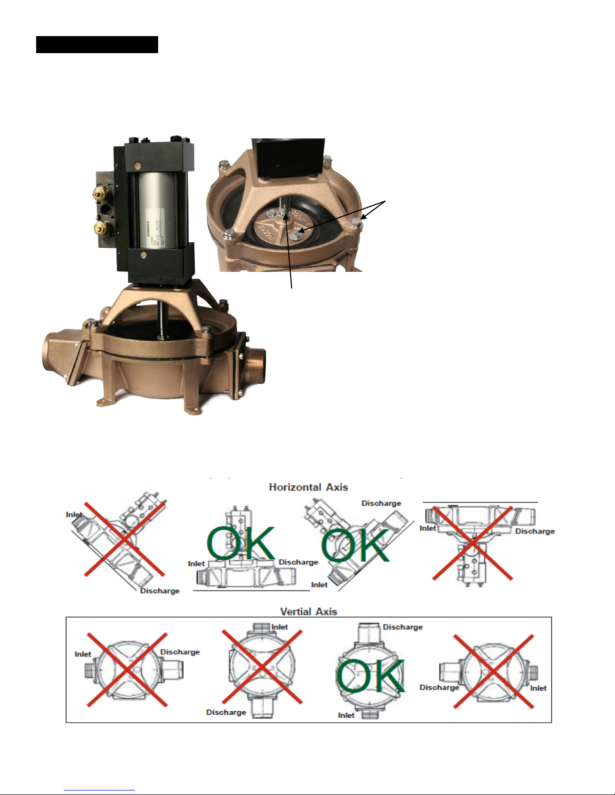
Step 1 Check All Bolts - Make sure that all bolts on the pump are tight. Tools: 2ea. 9/16”, 1/2” and
7/16” Box Wrenches & 1 Allen Wrench.
7/16”
Upper Standard
& Head Ring
1/2”
9/16”
Cylinder Rod
Locking Nut
Cylinder Mounting Nuts (Not Shown)
Step 2 Place Pump - The pump must be installed so that the flapper valves will open and close. The drawings
below show how the pump can and can not be installed in relationship to its’ horizontal and vertical axis.
Page 3 Installation
Page 4

P-220A-03
Step 4 Connect The Air Line - Air line should be at least 1/4” pipe or hose. It should deliver at least 8 ACFM and
regulated between 85 and 95 psi. The air line is connected to the 3/8” FNPT located between the two
exhaust regulator filters.
Step 5 Speed Control Muffler - The needle valve that is part of this exhaustPXIIOHU is used to adjust the speed of
the down stroke and up stroke of the cylinder. Using this adjustment the cycle rate of the pump was set to
60 cycles per minute
Important
Air Pumps are factory set to 60 cycles per minute with the input air
holding at 85 psi run pressure and no liquid being pumped.
Speed Control Muffler
Part No.161-A-2990
controls the speed of the
up stroke of the cylinder
3/8” Female NPT
Air Line Connection
Speed Control Muffler
Part No.161-A-2990
controls the speed of the
down stroke of the cylinder
Important
Do not control pump cycle rate by increasing or decreasing air line pressure.
Air line pressure should always be kept between 85 and 95 psi.
Step 6 Practice Adjusting The Pump Cycle Rate - There are two ways to control the cycle rate. The first is by
adjusting the needle valves of the Exhaust Regulator Filter. The second is by using an air flow control valve
on the air line between the pressure regulator and the air cylinder. You can use either or a combination of
both adjustments to set the pump performance you need once the plumbing is installed and liquid is being
pumped.
1. Open the air line.
2. Set air line pressure to 90 psi.
3. Using a very small flat head screwdriver start closing (clockwise) the right hand solenoid needle valve. The
down stroke of the air cylinder should start slowing down.
4. Now close the upper needle valve. The up stroke of the air cylinder should start to slow.
5. Now reset the cycle rate to 60 cycles per minute by opening each needle valve till you are getting one
down stoke per second and you perceive that the timing on the up stroke and the down stroke is
approximately the same. Use a watch with a sweep second hand to time the cycle rate.
6. Now open and close the air flow control valve if you want to use one and note the change in cylinder
speed.
Page 4 Installation - Air Line
Page 5

P-220A-03
Step 7 Install Plumbing - Good pump performance requires plumbing to be installed properly for this pump.
l DO NOT INSTALL THE PUMP AND PLUMBING
SO AIR WILL BE TRAPPED.
BECAUSE trapped air can completely restrict the
flow, or at the least require more work from the
pump resulting in early diaphragm failure. Install
pump and plumbing so any air introduced into the
plumbing will not be trapped but flow naturally
through liquid and out of the system.
l SHOULD NOT INSTALL PUMP WITH POSITIVE
HEAD ON THE INLET - Under standard operating
guidelines the pump should be above the liquid it is
being used to transfer.
BECAUSE of the flow through check valves,
stopping the pump will not stop the liquid from
flowing. Under the force of gravity liquid will pass
right through a diaphragm pump. Also consider a
diaphragm pump can not control a siphon
condition. They are used many times to start one.
l DISCHARGE FITTINGS, PIPE AND HOSE
SHOULD ALL BE THE SAME SIZE AND NEVER
BE SMALLER THAN THE INLET.
BECAUSE a smaller discharge line increases
work for the pump and increases the possibility
of clogging.
Don’t
OK
Don’t
OK
DON'T
Inlet
2" ID
Discharge
1.5"ID
l USE ONLY LONG RADIUS ELBOWS.
BECAUSE a they reduce back pressure and
wear on the pump diaphragm. When pumping liquid
with solids they help prevent clogs in the plumbing.
l INSURE ALL HOSE AND FITTINGS ARE AIR
TIGHT.
Because self priming performance depends on air
tight suction line. It prevents leaks
OK
OK
Air Tight
Against
Vacuum
146 DUCHAINE BLV D., NEW BEDFORD, MA. 02745-1292 TEL. 508- 995-9711 FAX 508- 995-5021 E -MAIL pumps@eds onint l.com
Page 5 Installation - Plumbing
Page 6

Operation Guidelines
Running The Pump Dry:
This Pump will run dry indefinitely without damage.
Pumping Liquids with Suspended Solids:
l KEEP SOLIDS IN SUSPENSION - When the pump
is used to pump solid matter such as sludge at
the bottom of a tank, or to dredge out a section of a
lagoon make, sure the solids have enough liquid
mixed in to allow it to flow. Raking or stirring while
the pump is pumping will keep solids in
suspension. Rule of thumb in pumping viscous
liquids or combinations of liquids with solids, "If It
Will Not Flow Through A Line Under Gravity, The
Pump Will Most Likely Not Pump It."
l FLAPPER CHECK VALVES AND SOLIDS -
Solids trapped under the check valves will
prevent self priming. This is likely to occure when
the pump is used in sewage or sump pump out
applications . Flushing with water will generally
clear out the solid matter. Installing secondary
clear flapper check valves right at the inlet and
discharge will improve the dry suction start
performance of the pump and make clearing the
valves easy. Order Edson Clear Check Valves
69CL-150 (1.5").
l PUMPING AT THE PROPER SPEED - When
pumping liquid with solids the speed may be too
slow to keep the solids and the liquid combined.
The solids will stop moving and begin to clog the
line. Pumping at a faster rate or decreasing the
hose size to increase velocity may be the solution.
Check With Edson Customer Service.
l USING A STRAINER ON THE INLET - If the
solids are too large they will block the inlet or get
stuck in the suction line. The end a suction hose
can become attached to a flat surface cutting off
all flow. Using an Edson strainer will prevent
these conditions. Order an Edson Shatterproof
Bronze Strainer 111BR - 150
P-220A-03
Discharge Loop
l USING A DISCHARGE LOOP - For sewage and
sump applications when the discharge drains
naturally down and away from the pump, installing
an 8” to 10” positive loop right on the discharge port
will improve the self priming feature. When you
stop pumping the loop traps some liquid against
the discharge valve improving the seal.
146 DUCHAINE BLV D., NEW BEDFORD, MA. 02745-1292 TEL. 508- 995-9711 FAX 508- 995-5021 E -MAIL pumps@eds onint l.com
Page 6 Operation Guidelines
Union Ball Valve
PVC Pipe Adapter
Union Check Valve
Page 7

How The Pump Works
l The air cylinder housing raises and lowers the diaphragm.
l Raising the diaphragm creates a vacuum.
l The vacuum forces the discharge valve assembly closed.
l Atmospheric pressure pushes liquid and/or air up the inlet plumbing to fill the vacuum.
l When the diaphragm is driven down the air and liquid under the diaphragm is compressed
closing the inlet check valve and forcing the air and liquid out the discharge.
l The closing of the inlet valve assembly also prevents the liquid and air trapped in the
inlet line from dropping back down (to atmosphere).
P-220A-03
Suction Stroke
Inlet Valve Assembly:
opens into the pump
Discharge Valve Assembly:
closes and seals on the valve
seat that is part of the pump
base under the discharge
chamber.
Pump Performance Tests:
l Volume Test - Tests overall performance of the pump installation.
1.Use a container with a known capacity of at least 2 gallons.
2.Empty the container using the suction side of the pump or fill it from the discharge.
When using the fill test make sure the pump is fully primed before filling the container.
3.Use a watch to record the time it takes. Repeat the test at least twice.
4.Establish GPM rate. Example 1: It took 10 seconds to fill a 5 gallon container. The
GPM rate is 30 Gallons Per Minute.(60 seconds divided by 10 seconds times 5 gal.)
Example 2: It took 10 seconds to empty a 2 gallon container. The GPM rate is 12
Gallons Per Minute.(60 seconds divided by 10 seconds times 2 gal.)
5.Record the cycle speed of the pump. Know the head conditions of your test and
compare the results of your test with the volume of the appropriate Volume Chart
on page 2. Every installation is different so use the charts as a guideline.
6.Example 1: The “fill test” at 30 GPM. The diaphragm is going up and down at 56
cycles per minute. The pump is approximately 6 ft. above the liquid. I disconnected the
installation discharge line and replaced it with a 3 ft. length of 2” hose so I could do the
fill test. Using the 56 cycle per minute Volume Chart from page 2, I know that at a
suction height of 5 ft. and a discharge height of between 0 and 5 ft. I should get
approximately 30 GPM. The installation is performing within the guidelines.
6.Example 2: The “empty test” at 12 GPM. The diaphragm is going up and down at 30
cycles per minute. The pump was approximately 5 ft. above the 2 gal. container and
the discharge line goes up 4 ft. From the 30 cycle per minute Volume Chart on page
2, I know that with a suction height of 5 ft. and a discharge height of 0 to 5 ft. I
should get approximately 17 GPM. The installation is performing below the
guidelines. See the Trouble Shooting section of this manual.
Discharge Stroke
Discharge Valve Assembly:
opens away from the pump
Inlet Valve Assembly:
closes and seals on the valve
seat that is part of the inlet
chamber.
l Vacuum Gauge Test - Tests the performance of the discharge valve and valve seat.
1.Attach a 5’ length of non-collapsing hose or pipe with a vacuum gauge installed
to the inlet of the pump. Make sure the line is completely sealed and air tight.
2.Turn on the pump and let it run till the gauge stabilizes. Record the reading.
3.Turn off the pump and watch the gauge.
4.If the discharge is working properly the gauge should build and hold at 10” to 12”hg.
Do not be concerned if the vacuum pressure slowly returns to 0 within a minute or so.
5.If you do not get any vacuum reading or if the gauge does not get to 10” hg and drops
off to 0 as soon as the pump stops, do the same thing again. Listen for air being
sucked in around the diaphragm. If you hear air movement, inspect for loose bolts or
worn diaphragm. If you hear no air movement, remove the discharge chamber and
inspect the valve assembly and valve seat. Clean or replace the valve and clean or
resurface the valve seat as appropriate. See Maintenance/Valve Assemblies
146 DUCHAINE BLV D., NEW BEDFORD, MA. 02745-1292 TEL. 508- 995-9711 FAX 508- 995-5021 E -MAIL pumps@eds onint l.com
Page 7 Operation Guidelines- Testing
Page 8

Maintenance
P-220A-03
l Pressure Gauge Test - Tests the performance of the suction valve and valve seat.
1.Attach a 5’ length of non-collapsing hose or pipe with a 0 to 15 psi gauge installed
to the outlet of the pump. Make sure the line is completely sealed and air tight.
2.Turn on the pump and let it run till the gauge stabilizes. Record the reading.
3.If the suction valve is working properly the gage should build and pulse at 6 to 7 psi.
and when the pump is stopped the pressure may hold or slowly returns to 0.
4.If you do not get any pressure reading or if the gauge does not get to 4 psi and drops
off to 0 as soon as the pump stops, clean or replace the suction valve and clean or
resurface the valve seat as appropriate. See Maintenance/Valve Assemblies
l Manual Test - Testing the pump valves and valve seats without the use of a gauge.
1.Remove all fittings from the inlet and discharge of the pump.
2.Turn on the pump.
3.Put your hand over the inlet. If the discharge valve is working properly, you should feel a
very strong pulsing suction. The pulsing coincides with the raising and loweringof the
diaphragm. If you do not feel any suction, do the same thing again and listen for
air being sucked in around the diaphragm. If you hear air movement, inspect for loose
bolts or worn diaphragm. If you hear no air movement, remove the discharge
chamber and inspect the valve assembly and valve seat. Clean or replace the valve
and clean or resurface the valve seat as appropriate.
4.Press your hand over the discharge. If the inlet valve is sealing properly, the
pressure of the pump down stroke should push your hand away. If it does not and the
air is forced out the inlet remove the inlet chamber and inspect the valve assembly
and valve seat. Clean or replace the valve and clean or resurface the valve seat as
appropriate. See Maintenance/Valve Assemblies
Diaphragm & Check Valves: Over time these parts wear and need to be replacement. The ability to
easily and quickly replace these inexpensive parts is one of the major advantages of an Edson diaphragm
pumps. Edson has packaged these parts as Spares Kits. See the parts list for the order #s.
l Change the diaphragm as required.
l Inspection and testing on a regular basis is recommended. For continuous duty application,
inspect the pump daily until a life pattern is established.
l Look for leaks, cracks or splits on the surface of the diaphragm.
l Life expectancy is directly related to head conditions, run time and diaphragm material. The
higher the suction and discharge pressures the shorter the life.
146 DUCHAINE BLV D., NEW BEDFORD, MA. 02745-1292 TEL. 508- 995-9711 FAX 508- 995-5021 E -MAIL pumps@eds onint l.com
Page 8 Maintenance
Page 9

Valve Assemblies & The Valve Seats: The sealing of the flapper valves are what makes the diaphragm
pump work. If the valves are not sealing properly, the pump will not be performing to full potential
or may not be pumping at all. The valves tend to last longer than the diaphragm. When you
change the diaphragm inspect the valves for cracks and delamination and the valve seats for
pitting and any build up that will prevent the valve rubber from sealing effectively. Testing the
pump is the best way to evaluate performance.
l Change the valve assemblies as required.
l Inspection and testing on a regular bases is recommended. For continuous duty application,
inspect the pump daily until a life pattern is established.
l See Pump Performance Tests .
P-220A-03
Trouble Shooting
The Edson Air Powered Diaphragm Pump is very simple and problems are usually isolated to the following components:
l Suction and Discharge Plumbing
l The Diaphragm and Valves
l The Air Cylinder
1.Problem
Pump is running, liquid
is not moving.
2.Problem
Air Cylinder is not going
up and down.
a. Suction line is blocked.
b. Suction line has air leak
between liquid and inlet of the
pump.
c. Discharge and/or suction
valves are not working.
d. Diaphragm has a leak.
e. Discharge or suction line is
to high.
a. Air pressure is low.
b. Discharge or suction line is
blocked.
c. Air cylinder is malfunctioning.
Possible Causes
Possible Causes
Action
If the cause is not obvious, isolate the source.
Disconnect the inlet and discharge plumbing from
the pump and perform the Manual Test. If the
cause is not in the pump check for a block or an
air leak in the suction line. Suction air leaks can
be cumulative and can be as simple as one or two
fittings not being sealed properly. Review Plumbing
Action
If the cause is not obvious, isolate the source.
Check air line for pressue and flow. If ok, disconnect the inlet and discharge plumbing from the
pump and restart the pump. If pump cycles without
the plumbing connected, there could be a clog in
the lines. The back pressure caused by a complete blockage in the inlet and discharge line will
stop the pump. If the pump cylinder still does not
cycle then the problem is in the air cylinder. See
air cylinder section.
146 DUCHAINE BLV D., NEW BEDFORD, MA. 02745-1292 TEL. 508- 995-9711 FAX 508- 995-5021 E -MAIL pumps@eds onint l.com
Page 9 Maintenance
Page 10

P-220A-03
3.Problem
Diaphragm is wearing
out much earlier than
expected.
4.Problem
Pump base and/or lines
keep filling with solids
Parts 220ACB-150
Possible Causes
a. Liquid being pumped is not
compatible with the
diaphragm material.
b. Discharge and/or suction
back pressure too high.
Possible Causes
a. Line velocity is too slow to
keep the solids in suspen
sion.
b. The percent of solids is too
high.
Action
Consult a chemical resistance chart. If material
being pumped is compatable with the diaphragm
being used, review the pump performance
specifications and installation guidelines in
respect to the installation. Diaghragm life will be
reduced with the increase in discharge and
suction head. Expected diaphragm life is different
based on the material and style of the diaphragm
used. Call Edson Customer Service for details.
Action
Speeding up the pump will help increase the
velocity. Using a strainer can reduce the size and
percent of solids. Diluting the slurry by increasing
the amount of liquid or by increasing the agitation
of the mix may solve the problem.
1/4-20 X 2” HHCS w/Nut & Washer
10-32 X 3/4” PHMS w/Nut
160-B-376B
Discharge Chamber
160-A-1207 Valve Assembly
160-B-378B
Pump Base
161 B-387B
Adapter Frame
5/16-24 Nut
161 A-2994 Air Cylinder,QFOXGHV$6SHHG&RQWURO0XIIOHUV
1/4-20 X 3/4” HHCS
160-A-1253 Sealing Washer
161-A-1008 Upper Standard
113N-18 Nitrile Diaphragm
161-A-1006 Lower Standard
160-B-374B Head Ring
160-A-1207 Valve Assembly
160-B-375B
Suction Chamber
10-32 X 3/4” PHMS
146 DUCHAINE BLV D., NEW BEDFORD, MA. 02745-1292 TEL. 508- 995-9711 FAX 508- 995-5021 E -MAIL pumps@eds onint l.com
Page 10 Parts
Page 11

Parts 220ACA-150
P-220A-03
161 A-2994 Air Cylinder,QFOXGHV$6SHHG&RQWURO0XIIOHUV
Discharge Chamber
Parts: Spares Kits
Nitrile
Order No. 114N 18-220
1 Diaphragm 113N -18
2 Valve Assemblies 160 A-1207
2 Sealing Washers 160 A-1253
160- B-387B
Adapter Frame
1/4-20 X 2” HHCS w/Nut & Washer
10-32 X 3/4” PHMS w/Nut
160-B-376A
160-A-1207 Valve Assembly
160-B-378A
Pump Base
Pump Spares Kits:
160-A-1253 Sealing Washer
161-A-1008 Upper Standard
113N-18 Nitrile Diaphragm
5/16-24 Nut
161-A-1006 Lower Standard
10-32 X 3/4” PHMS
Viton
Order No. 114V 18-220
1 Diaphragm 113V - 18
2 Valve Assemblies 160 A-1207V
2 Sealing Washers 160 A-1253
1/4-20 X 3/4” HHCS
160-B-374B Head Ring
160-A-1207 Valve Assembly
160-B-375A
Suction Chamber
Viton
Order No. 114V 18-220
1 Diaphragm 113V - 18
2 Valve Assemblies 160 A-1207V
2 Sealing Washers 160 A-1253
146 DUCHAINE BLV D., NEW BEDFORD, MA. 02745-1292 TEL. 508- 995-9711 FAX 508- 995-5021 E -MAIL pumps@eds onint l.com
Page 11 Parts
 Loading...