

Edsal 3000 User Manual
Quick Assemble Welded Frame Storage Cabinets
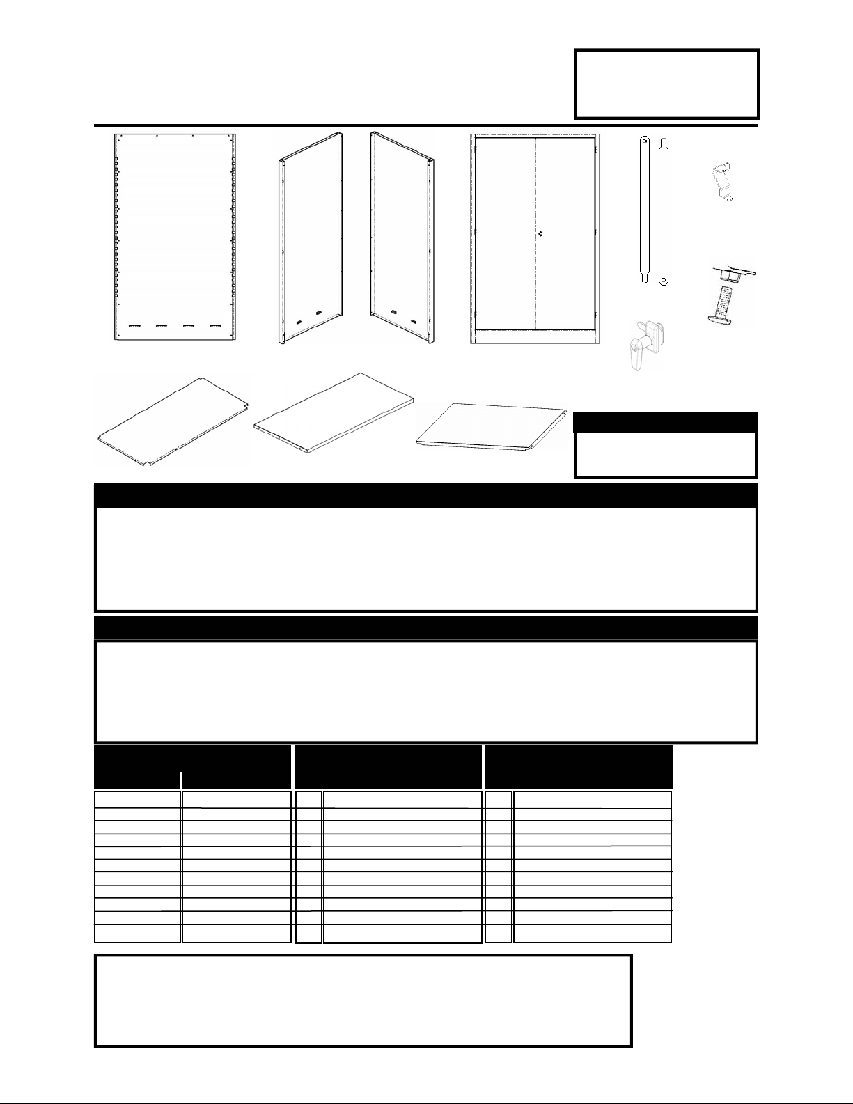
(A) Back
(B) Right Hand Side (C) Left Hand Side
(H) Door Frame
MODELS
3000
3000
3000
3001
3001
3001
(J) Locking Handle
-
1UEY1
-
1UEY2
-
1UEY1
-
1UEY2
-
1UEY1
-
1UEY2
-
1UEY4
-
1UEY5
-
1UEY4
-
1UEY5
-
1UEY4
-
1UEY5
(I) Door Rods
-
1UEY3
-
1UEY3
-
1UEY3
-
1UEY6
-
1UEY6
-
1UEY6
Page 1
(G) Shelf Clips
(K) Leg Leveler &
Cage Nut
Required Tools
Required Tools
Required Tools
• Small Screwdriver
(F) Shelves
• Rubber Mallet
Safety Instructions
Safety Instructions
Safety Instructions
(D) Top (E) Bottom
Use Caution when handling and assembling metal parts. The metal may have sharp edges or corners.
The use of protective gloves is recommended. Do not use this unit for anything that is outside the designed function of storage. Do not store loose or heavy items on the top shelves or on the top of the
unit, for they create a falling hazard that can injure yourself or others. Always remember to use proper
lifting techniques when moving either the boxed or assembled unit.
General instructions
General instructions
General instructions
It is recommended that the cabinets are assembled by more than one person. Use of a raised
flat surface during assembly is highly recommended. During shipping and handling, some of the
panels that are used for assembly may have become bent. Use your hand to pry up or push the
parts back to their original form. To assure that the unit is square. Make sure that the unit is
placed on a level surface, as this may effect the performance of the unit.
Part List & Product Specification
Part List & Product Specification
Part List & Product Specification
Reference
Reference
Reference
A
B
C
D
E
F
G
H
J
K
I
(patent pending)
(patent pending)
(patent pending)
Description
Description
Description
Right Hand Side
Left Hand Side
Shelf Clips
Door Frame
Door rods
Locking Handle
Leg Leveler & Nut
Back
Top
Bottom
Shelves
4 Shelf
–
78” h x 18” d x 36” w
4 Shelf
–
78” h x 18” d x 36” w
4 Shelf
–
78” h x 18” d x 36” w
3000
3000
3000
1
1
1
1
1
4
8
1
2
1
2
-
1UEY1
-
1UEY2
-
-
1UEY2
-
1UEY2
1UEY3
-
1UEY3
-
1UEY3
-
1UEY1
-
1UEY1
CUBK7837 KA
CUSD7820R KA
CUSD7820L KA
CUTO3820 KA
CUBO3617-1 KA
CUSH3718-1 KA
7000CLP
3000FRAME KA
CUDR3500 KA
201L
Leveler 100
1
1
1
1
1
4
8
1
2
1
2
4 Shelf
–
78” h x 24” d x 36” w
4 Shelf
–
78” h x 24” d x 36” w
4 Shelf
–
78” h x 24” d x 36” w
3001
-
1UEY4
3001
-
1UEY4
3001
-
1UEY4
CUBK7837 KA
CUSD7826R KA
CUSD7826L KA
CUTO3826 KA
CUBO3623-1 KA
CUSH3724-1 KA
3001FRAME KA
CUDR3500 KA
-
1UEY5
-
1UEY6
-
1UEY5
-
1UEY6
-
1UEY5
-
1UEY6
7000CLP
201L
Leveler 100
Should you have any comments, damage, missing parts, or problems with assembly of this unit please feel free to contact
our Edsal manufacturing facility at, (773) 475-3000 and request customer service. We can also be reached on the internet
at the following email address : customerservice@edsal.com.
To obtain replacement parts, please provide the following information :
- Model # - Part # & Description - Location Purchased - Date Purchased
Consumer Products Division
Edsal Manufacturing Company
4400 South Packers Avenue
Chicago, IL 60609
www.edsal.com
Made In China
Assembly Instructions : Edsal 3000KA & 3001KA Series Storage Cabinets Page 2
Assembly Instructions : Edsal 3000KA & 3001KA Series Storage Cabinets Page 2
Assembly Instructions : Edsal 3000KA & 3001KA Series Storage Cabinets Page 2
Important Please Read First
Important Please Read First
Important Please Read First
This instruction sheet was designed to help you assemble this unit in the proper way, please follow them using all
parts and fasteners provided. Any alteration or deviation from this instruction sheet can result in unit failure. If
you have any assembly problems or questions, please feel free to contact our Edsal manufacturing facility at
(773) 475-3000 during the hours of 9:00 a.m. to 5:00 p.m. central standard time and ask for customer service.
We have people available to assist you if need be with any part of this assembly process.
IT IS HIGHLY RECOMMENDED TO ASSEMBLE THIS UNIT AT EYE LEVEL, AND WITH THE HELP OF AN
ADDITIONAL PERSON. Using a RAISED surface such as a TABLE or DESK, will greatly EASE the ASSEMBLY
PROCESS. Assembly attempted on a much lower surface such as the floor, is still possible but does make the
assembly process longer and harder. During the shipping and handling of this product, some of the panels may
have a MINOR bend such as on a corner, door hinge pin, or a tab. This minor variation can be REPAIRED SIM-
PLY by using a SMALL TOOL or your HAND to move the material back to its designed form. A example will be
outlined in the “GETTING STARTED” section listed below. Some of the materials used in the packaging to protect the parts from damage may leave dust or smudges on the steel panels. It is RECOMMENDED AFTER AS-
SEMBLY IS COMPLETE to use a MILD SOAP and WATER with a SOFT CLOTH to wipe the unit clean.
Getting Started
Getting Started
Getting Started
This assembly process uses tabs, notches, rectangular, and square holes to hold the parts together. To
speed the assembly process, have a rubber mallet, and a small blade screwdriver ready. After unpacking all
the panels, visually inspect the corners. These are the most susceptible to damage through the shipping
and handling process. If you find a corner bent out of place, use your hand and gently move the corner back
to the designed shape. Also during shipping and handling some of the tabs used for engaging the panels
together may have become closed. Visually inspect all panels and if found that some are closed, use a small
blade screwdriver to push the tabs from behind to open slightly (it is recommend to push tabs out slightly for
ease of assembly, and then tap back down with a rubber mallet, to tighten engagement). A example of
pushing the tabs out and how the engagement process works, is shown below.
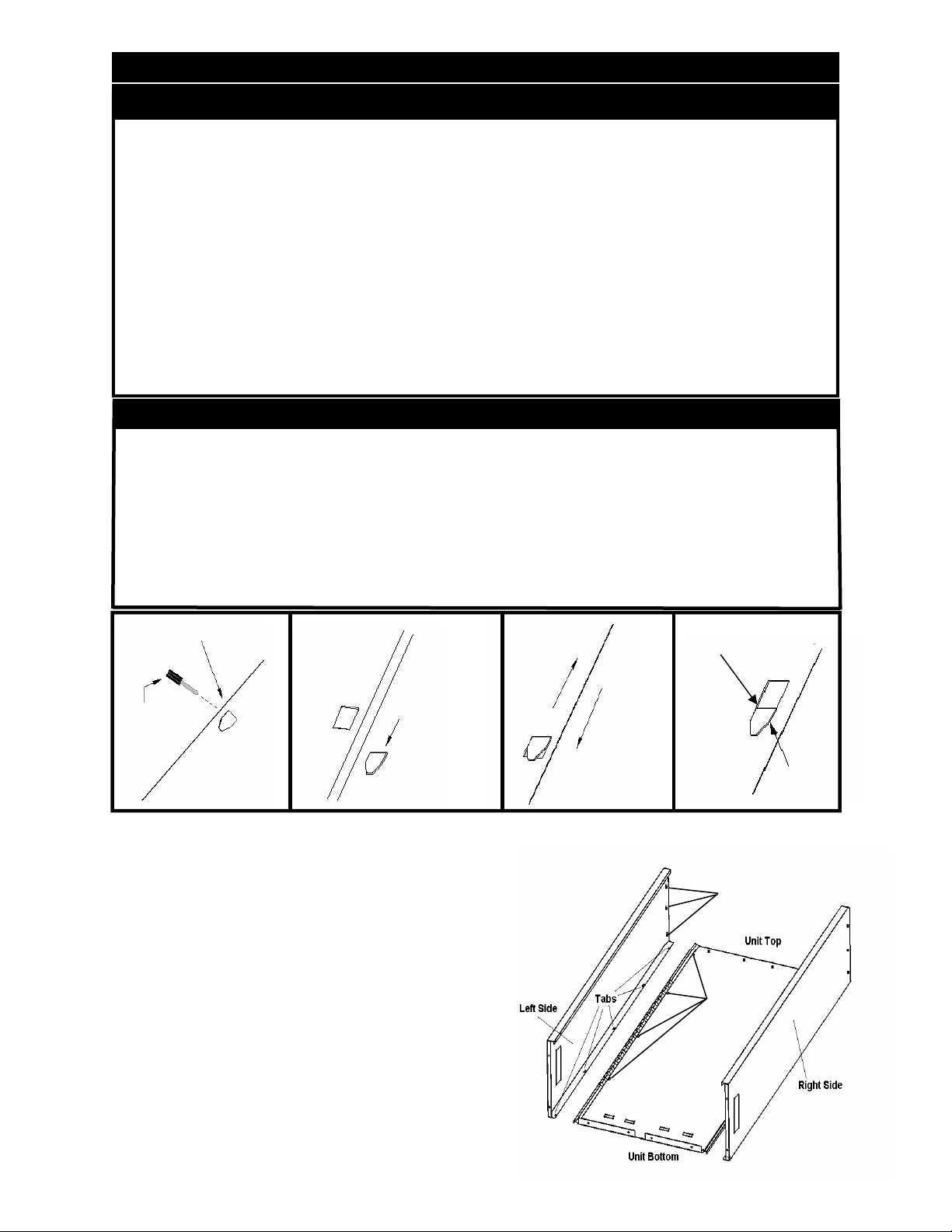
Push tab slightly
from back side
to open
Piece with tab
goes under piece
with rectangular
Small blade
screwdriver
hole
Step 1 - Side Assembly
First step is to identify the right side panel and the left
side panel. Identify by taking one of the panels and
place the tab edge facing down. Now look at the top and
bottom edges. The top of the side has a notches on the
flanges, and the bottom has a bend inward (see figure
1). Place the corresponding side panel under the back
assembly making sure the tabs of the side panel ride into
the rectangular holes of the back assembly. Slide the
parts together making sure that the tabs and rectangular
holes fully engage (if properly completed, the side and
back assembly will be even at both ends. After assuring
the correct side is fastened to the back assembly and the
tab engagements are complete, tap tabs down with a
rubber mallet to tighten the engagement. Repeat the
same process for the opposite side panel.
Slide part
Slide part
Tap tab with rubber
mallet to tighten
engagement
Tab fully engaged
Figure 1 - Side Assembly
Side top flange notches
Back’s
rectangular
holes
 Loading...