

EDS RK 100 R, RK 100 RS Technical Manual

EDS - TECHNICAL INSTRUCTIONS
1
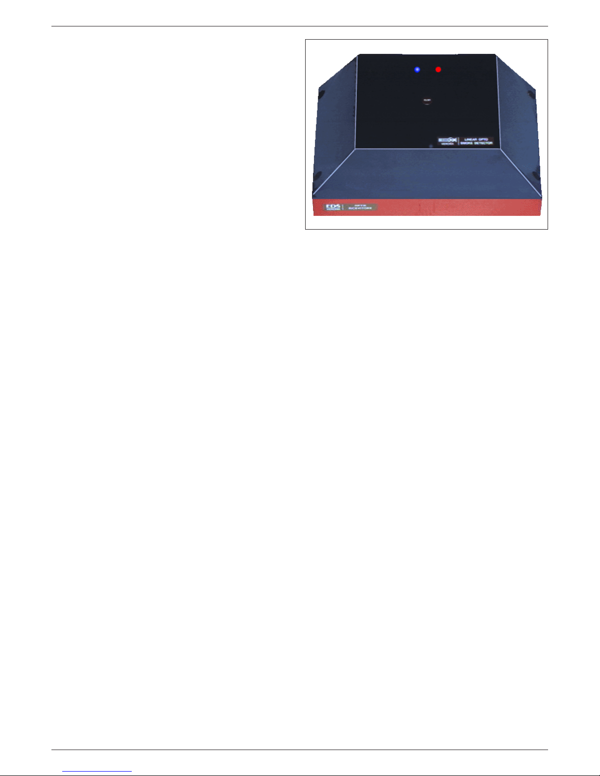
REFLECTIVE TYPE
OPTICAL BEAM LINEAR
SMOKE DETECTOR
RK 100 R
RK 100 RS
TECHNICAL MANUAL
TECHNICAL INSTRUCTIONS FOR
INST ALLA TION, SETUP AND
MAINTENANCE
EDS - V . Ca' Nova Zampieri 6 - 37057 S. G. Lupatoto - VERONA - T el. +39045547529 - Fax. +390458750065 - E.Mail: eds@eds.eu - Web: www.eds.eu

EDS - TECHNICAL INSTRUCTIONS
2
CHAPTER INDEX
1 - Qualified Personell
2 - Relevant Standards
3 - Installation
4 - Cable Connections
5 - Electrical Connections and Initial Setup
6 - Operation
7 - Optical Alignment
8 - Setup of Obscuration circuit
9 - Setup of Turbulence (heat) circuit
10 - Detector’s activation
11 - Autocompensation
12 - Operational Test
13 - Fault Output
14 - Alarm Memory
15 - Frontal Leds Operation
16 - Maintenance
17 - Sensitivity selection
18 - Technical data
QUICK INST ALLA TION
The procedure below is intended for trained personell with previous
experience in installing EDS Beam Smoke Detectors RK100R.
If you don’t have the needed experience please refer to the standard
installation procedure of this manual.
1 - fix the RK100R detector and FX reflector
2 - connect the cables
3 - set JP2-JP3-JP4-JP5-JP7 detector’s jumpers (see pag.10)
4 - make the optical allignment with the lamp
5 - set SW3 selector on the device according to the distance
between Detector and FX (see table in fig.7)
6 - place jumper JP1 in “ON” position (Alignment) and
power up the device
7 - optimize the device signal using:
• the P1 trimmer
• the adjustment screws V1-V2-V3 on the optical block
• a multimeter (or the STS01 instrument)
• blue/Red Led signal level indication (fig.8 board)
8 - regulate the signal between 4,7V and 5V with the P1
trimmer
9 - verify the functioning obcuring the FX
10 - select the desired sensitivity of the Obscuration circuit
with the SW2 selector (40-50-60-70%)
11 - select the desired sensibility of the Turbulence (Heat)
circuit with the SW1 selector (if used)
12 - set JP1 in “OFF” position to activate the device
13 - close the cover within 5 minutes
14 - wait at least 5 minutes for the device to become
operational
15 - perform operational tests
DEF AUL T F ACTOR Y SETTINGS
(Read ahead)
• SW1 - position 1 (minimum threshold level)
• SW2 - position 1 (minimum threshold level )
• SW3 - position 4 (maximum Transmitter power )
• JP1 - position 2-3 (optical allignment on)
• JP2-JP3 - position 2-3 (contact NC)
• JP4 - position 1-2 (contact NC for Fault relay))
• JP5 - position 1-2 (memory off)
• JP7 - not inserted (alarm relays NC)
• P1 - level adjustment trimmer at half scale
NOTE - the version RK100RS is not equipped with the detection circuit of Turbulence. Therefore there are no items
related to this circuit. In the reading and in the use of technical instructions, keep in mind this indication.
EDS - TECHNICAL INSTRUCTIONS
3
REFLECTIVE TYPE
OPTICAL BEAM SMOKE
DETECTOR
RK100R - RK100RS
GENERAL
The RK100R detector is a newly-conceived microprocessor
optical beam smoke detector, that bases its working concept on
the interaction between the smoke present in a room and an infrared
beam emitted by a transmitter and reflected by an optical reflector
(fig.1).
The normal installation consists in mounting the detector on a wall
of the room to be protected and in fixing the FX reflector (FX01,
FX02, FX03, etc depending on the distance- see table in fig.7) on
the opposite wall.
For a correct installation, we recommend to read and follow our
instructions carefully. The excellent working results of the device
will widely compensate the time spent reading these instructions.
1 - QUALIFIED PERSONELL
1.1 - All the operations of installation, setup, startup, maintenance
and verifications of operation of the RK100R detector, must only
be performed by qualified personnell. These people are qualified
for their experience, specialization courses, knowledge of the
current standards and of the technical specifications, features
and usage method of the product. These people therefore are able
to avoid errors or damages and assure an optimal functioning of
the product.
1.2 - The RK100R detector must be used according to the tecnical
data and to the information of this manual, to the installation and to
the ambiental and operational condition
2 - RELEV ANT ST ANDARDS
2.1 - For the installation in European Community countries you
must follow the EC standard EN54-14 (Fire detection and fire
alarm systems). In extraeuropean countries you must respect the
relevant international and national standards.
3 - INSTALLATION
3.1 - For the installation of the RK100R detector we suggest to also
use, besides the normal tools (drill, expansion plugs, etc), the
following elements:
• 1 - 7mm “C” Key
• 1 - alignment lamp (we recommend to use LAL02 lamp (optional) or
an electric torch with powerful and contrated beam)
• 1 - multimeter (we recommend an analogic hand T ester or an analogical
STS01 meter (optional) to be plugged on the special connector
positioned on detector’s circuit.
3.2 - Unscrew the 4 fixing screws (fig. 2) and remove the cover
3.3 - Install the detector at a distance from the ceiling within the
10% of the height of the room to protect. This distance can be
varied by the system designer if particular environmental conditions
exist. W all fixing must be done with care using the 4 holes provided
inside the container. If the wall is a solid masonry one, 4 expansion
plugs are enough. It’s extremely important that the fixing wall or
surface is rigid and not subject to deformations.
3.4 - Pass the cables through the holes obtained breaking the suitable
zones marked on the sides of the detector’s base.
It is important to use a suitable chock with a connecting pipe to
avoid that the dust penetrates inside the device, possibly causing
failure to its correct functioning.
3.5 - Install the FX reflector on the opposite wall at the same
distance from the ceiling as the detector. It is not necessary that
the device is perfectly in front of the optical reflector or
perpendicular to it (small angle shift are possible in all directions).
4 - CABLE CONNECTIONS
4.1 - The low current of the device (20 mA with normally open (NO)
alarm relay and 30 mA with normally closed (NC) alarm relay contact)
allows to use small size section cables. W e suggest a shielded cable
with 8 conductors + the shield ( 2x0,75 mmq for power conductors +
6x0,22 mmq for the signal conductors) for a distance up to 1 Km.
In such way it’s possible to take at distance:
• alarm signal (C1-N1 terminals)
• alarm signal for the tourbolece (C2-N2 terminals)
• fault (C3-N3 terminals)
• analog signal output (SIG terminal) - for level signal
measurement from distance
The cable shield must be connected as in fig.12

EDS - TECHNICAL INSTRUCTIONS
4
5 - ELECTRICAL CONNECTIONS AND INITIAL SETUP
5.1 - Connect the device cables as shown on fig. 11 and fig.12.
The used symbols indicate what follows:
• (V+) - (V -) - supply’s terminals 11 - 30 Vcc.
• (C1) - (N1) - normally closed alarm relay contact. The connection
is valid when the detector is not in alarm state and JP2 jumper is in
2 - 3 position. If JP2 is positioned on 1-2 the contact results
normally open. C1-N1 terminals are voltage free.
• (C2) - (N2) - turbulence alarm normally closed contact relay.
Connection is valid when the detector is not in an alarm state and
JP3 jumper is in 2 - 3 position.. If JP3 is positioned on 1-2 the contact
results normally open. C2-N2 terminals are voltage free.
• (C3) - (N3) - normally closed fault relay contact. Fault relay is
normally powered (intrinsic safety). Connection is valid when the
detector is not in fault state and JP4 jumper is in 1 - 2 position. If
JP4 is in 2-3 position the contact is normally open. C3-N3
terminals are voltage free.
• (SIG) - 0-5V analog output terminal. T o use only during allignment.
5.2 - JP SETTINGS :
JP1- To enter/exit the optical alignment procedure. To activate
the procedure of optical alignment JP1 must be in 2-3 (ON)
position. T o deactivate the procedure of optical alignment JP1 must
be in 1-2 (OFF) position.
• JP1 position 2-3 (ON).........alignment procedure ON
• JP1 posizion 1-2 (OFF).......alignment procedure OFF
JP2 - JP3 - JP4 - T o set the output contacts respectively of Alarm
relay, Turbulence relay and Fault relay to normally closed NC or
normally open NO (cap. 5.1)
The RK100R detector is normally factory preset with normally closed
NC contacts. For the alarm relay the indication of JP2 is valid if JP7
is in OFF position.
JP5 - Activate the alarm memory function or to deactivate that
function (detector automatically resets alarm output)
• position 1-2 alarm memory OFF. When the detector gets out of
alarm condition it automatically resets the alarm output
• position 2-3 alarm memory ON. In case of alarm the detector’s
alarm output persists until power supply is switched off for at least
5 seconds
JP6 - Microprocessor reset (SW reset)
JP7 - Selection of alarm relay operational mode : normally
powered (NC) or not powered (NO)
• JP7 ON - relay of alarm normally powered (in case
of alarm the relay gets not powered). In this case the indication of
the JP2 is inverted
• JP7 OFF - relay of alarm normally not powered (in case of alarm
the relay gets powered). In this case the indication of JP2 is according
to figures 11-12 (diagrams of the terminal block and the classical
scheme of connection to a control system to terminated lines)
6 - OPERA TION
6.1 - The RK100R detector is equipped with 2 circuits of detection
of the smoke produced by a fire:
• Obscuring - circuit sensitive to the obscuring.
This circuit founds its operation on the diminution of the infrared
ray intensity, along the optic run between the detector and the
reflector, caused by the smoke
• Turbulence - circuit sensitive to the Turbulence.
During the beginning phase of the fire, generally there are some
clouds of smoke and warm air that climb toward the ceiling. When
these clouds and warm air intercept the infrared ray produced by
the detector, they provoke a perturbation of it because produce a
variation of optic-physics characteristics in the transmission of the
infrared ray. This variation is obviously time correlated. An opportune circuit has been projected to reveal this variation and, when
these reach the ampleness and the duration in the time programmed,
a signal of alarm is produced. The sensibility and the delay of
intervention of this circuit are independently adjustable so that to
fully satisfy the applications of the technician. The advantage offered
by this circuit is a great speed of fire detection, because it is detected
in dynamic way in its initial phase.
7 - OPTICAL ALIGNMENT
7.1 - Proceed with the optical alignment of the detector and FX
reflector. To facilitate the operation we suggest to do it in low
ambient light conditions and to proceed in the following way:
• place in front of the reflector FX (fig.3) an optical alignment lamp
able to project a concentrated and sufficiently intense light beam.
(we recommend the EDS alignment lamp LAL02)
• direct the light beam of the lamp to the lenses of the detector
• look at the screen that is behind the lens, inside the Transmitter
(right lens). On it you will see a bright point that represents the
image of the lamp
• move the optical block using her special screws V1-V2-V3 with a
key, so that the bright point falls in the center where a small hole is
present through which the photodiode is visible (fig.4). It’s important
that the bright point falls on the photoemitting zone of the
photodiode. This zone is represented by the small dark dot in the
center of the photodiode (fig.4). In such way the detector will be
alligned with the reflector FX.
After doing the optical alignment of the detector it is necessary to
do the electric signal setting operations, proceding with the following
instructions.
8 - SETTING OF THE OBSCURA TION CIRCUIT
Setting Operations of the electric signal must be perform
according to the following sequence:
8.1 - Do not power supply the detector
8.2 - Rotate the SW3 selector in one of the positions 1-2-3-4
(fig.9) according to the distance between the detector and the
reflector (FX01-FX02-FX03, etc.) (reference fig.7)
8.3 - Move the jumper of Initial Set JP1 (fig.9) in the position ON
(Alignment) to activate the phase of initial setting
8.4 - Power up the detector
8.5 - The blue led and the red one will start to work in the way
described ahead in cap. 8.12. Before going on to this chapter read

EDS - TECHNICAL INSTRUCTIONS
5
what’s following
8.6 - the P1 trimmer (regulation of the signal level) is regulated in
factory to the 50-60% and it corresponds to a signal of 5V to the
maximum distance
8.7 - To get the best results in the following operations, we
recommend the use a measuring instrument (Multimeter),
preferably an analog hand type, for better control of the variations
of the signal during the setup. Good results are also obtained using
analog meter STS01 (optional), designed for this application, that
must be inserted on the special connector CN4, set on the printed
circuit of the detector (v. fig. 11). If you don’t have a Multimeter
or the STS01, you can perform the setup operations anyway
evaluating the signal level with the frontal Leds indications as
described in chap.8.12
8.8 - If available, connect a 5V fullscale multimeter between the
SIG terminal and the negative power supply one and read the analog
output signal. Instead of the multimeter, it is possible to use the
STS01 meter (optional - fig. 11). If the output signal is very low , it
means that the operations of optical alignment described in chapter
5, have not been performed in the right way and therefore must be
repeated
8.9 - The detector emits a conic beam which form and dimension,
in relation with the distance between detector and FX, are
explained in figures 5 -6.
It’s important that the FX is in the center of the detector’s conic
beam because, under these conditions, even if some small movements
of the wall on which the transmitter is mounted on happen (caused
by deformations), the reflector remains always within the beam and
therefore active.
T o obtain this, the operations of fine centering with output signal
measuring, explained below, must be performed with car e.
8.10- Regulate the signal to about 3V acting on the trimmer P1
(fig.9)
8.11 - Search for the maximum output signal optimizing the optical
alignment of the Transmitter acting slowly and in sequence on the
3 screws of regulation V1-V2-V3 set on the optic crew. This procedure take some time however, if well performed, it assures a
perfect work of the detector for many years. We advise to use the
following procedure:
• On the detector slowly turn the screw V1 clockwise and then
look at the value of the signal visualized on a multimeter. If the
signal increased (for example from 3V it rised to 3,5V) then again
turn the screw V1 of the detector clockwise and then look at the
value of the signal.
• Continue with this procedure as long as the signal increases.
When it has the tendency to decrease instead, stop the operation
on the screws V1 of the detector returning to the previous position.
• If during the operation the signal overcomes 4,5V, to avoid the
saturation, act on the trimmer P1 to bring the signal back to 3 V,
allowing the best evaluation of the variations of the signal.
• After finding out the maximum og the signal acting on the screw
V1, perform the same operations on the screws V2 and V3.
In such way the best possible position of optical allignment is
reached. This procedure is important because it will assure a perfect
operation of the detector for long time.
8.12 - If you don't have a multimeter, it is still possible to get good
results in the optical alignment of the detector, looking at the
detector’s blue and red leds indications. Operation is the following:
• 1 flash of the blue Led: 1 Volt
• 1 flash of the red Led: 0.5 Volts
• if the signal is smaller of 0.5V the blue led and red one are off
• if the signal in the range 0.5-1 V the red led performs 1 flash,
remains off for 2 seconds and then it repeats the sequence
• if signal is among 1-1.5 V the blue led flashes once, remains
off for 2 seconds and then it repeats the sequence
• if signal is among 1.5-2V the blue led flashes once and the red
led flashes once. They remain off for 2 seconds and then the
sequence is repeated
• if signal is among 2-2.5 V the blue led flashes 2 times, remains
off for 2 seconds and then it repeats the sequence
• if signal is among 2.5-3V the blue led flashes 2 times and the
red led flashes once. They remain off for 2 seconds and then
the sequence is repeated
• same type of indication up to 4 V
• if the signal overcomes 4 V, the blue Led flashes faster and
faster as the frequency signal increases up to 4.7V
• when the signal overcomes the 4.7V and in the range 4.7V -
4.9V, the blue led is continously ON. This is the position of
optimal setup
• if the signal gets over 4.9V the two blue and red leds are
permanently on. This is the saturation indication.
The table of fig.8 recaps the leds operation.
8.13 - After doing the operations of fine optical alignment using
the Tester or the indications of the Leds, you must regulate the
signal slowly acting on the trimmer P1, between 4.7V and 4.9V.
When the signal it is included within this range, the blue Led is
costantly ON. This it is the position of optimal setup. If the signal
overcomes the 4.9V, the detector goes in saturation and the blue
and red leds are both ON. Therefore acting on P1, it is necessary
to set the signal between 4.7-4.9V so that the red Led switches
OFF and is only the blue Led remains ON (to avoid saturation).
Attention! - this regulation is not critical. The procedure
indicated above is the optimal one, but it is enough if the blue
Led is flashing or constantly ON to have a good setting.
However it is necessary to avoid the saturation (red Led ON).
The microprocessor automatically compensates the
inaccuracies of the setting.
8.14 - It must be checked out that, since the detector founds its
operation on the reflection of the projected beam, this reflection
is effected by the FX reflector only and not from other elements.
T o be certain that the signal is produced by the reflection of its FX
reflector and not from other elements, it is useful to do a simple
verification. It is necessary to obscure the reflector with a non
reflecting screen (opaque). In that case the signal on SIG terminal
must decrease under 0,5V. (check indications in the following
pages).
8.15 - Select the alarm threshold level of the circuit sensible to
obscuration acting on the selector SW2 keeping in mind the
following :
• position 1 - low sensitivity - obscuration alarm threshold set to 70%
• position 2 - low to medium sensitivity - obscuration alarm threshold set
to 60%
• position 3 - medium to high sensitivity - obscuration alarm threshold
set to 50%
• position 4 - high sensitivity - obscuration alarm threshold set to 40%
8.16 - Sensitivity must be regulated according to the environmental
 Loading...